Downloaded 101 times
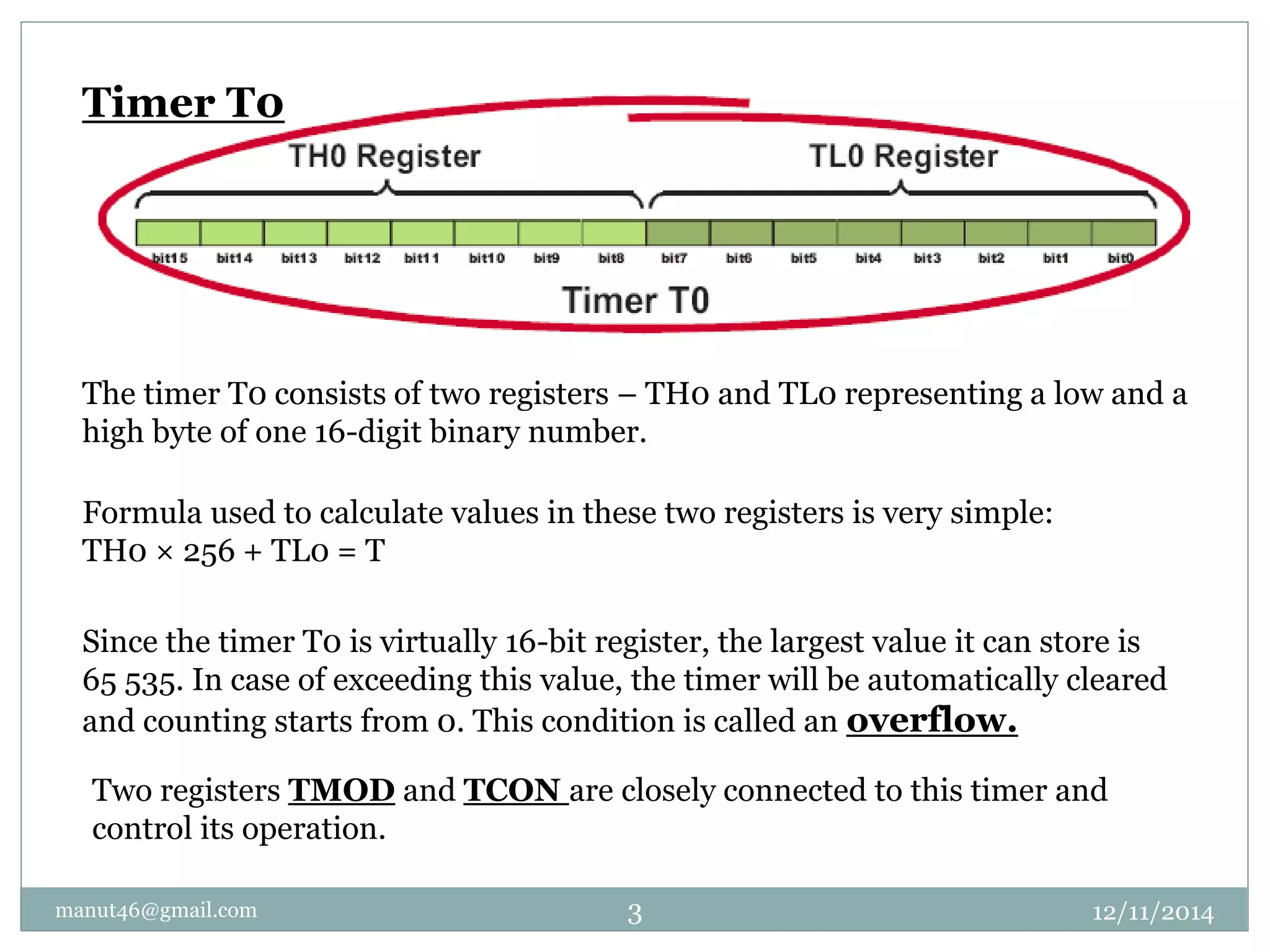
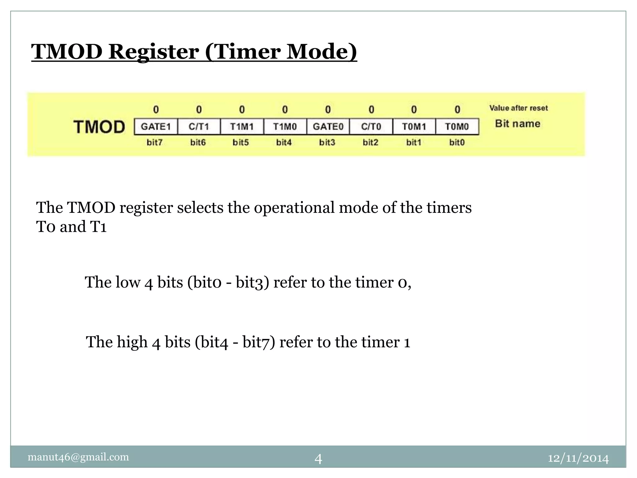
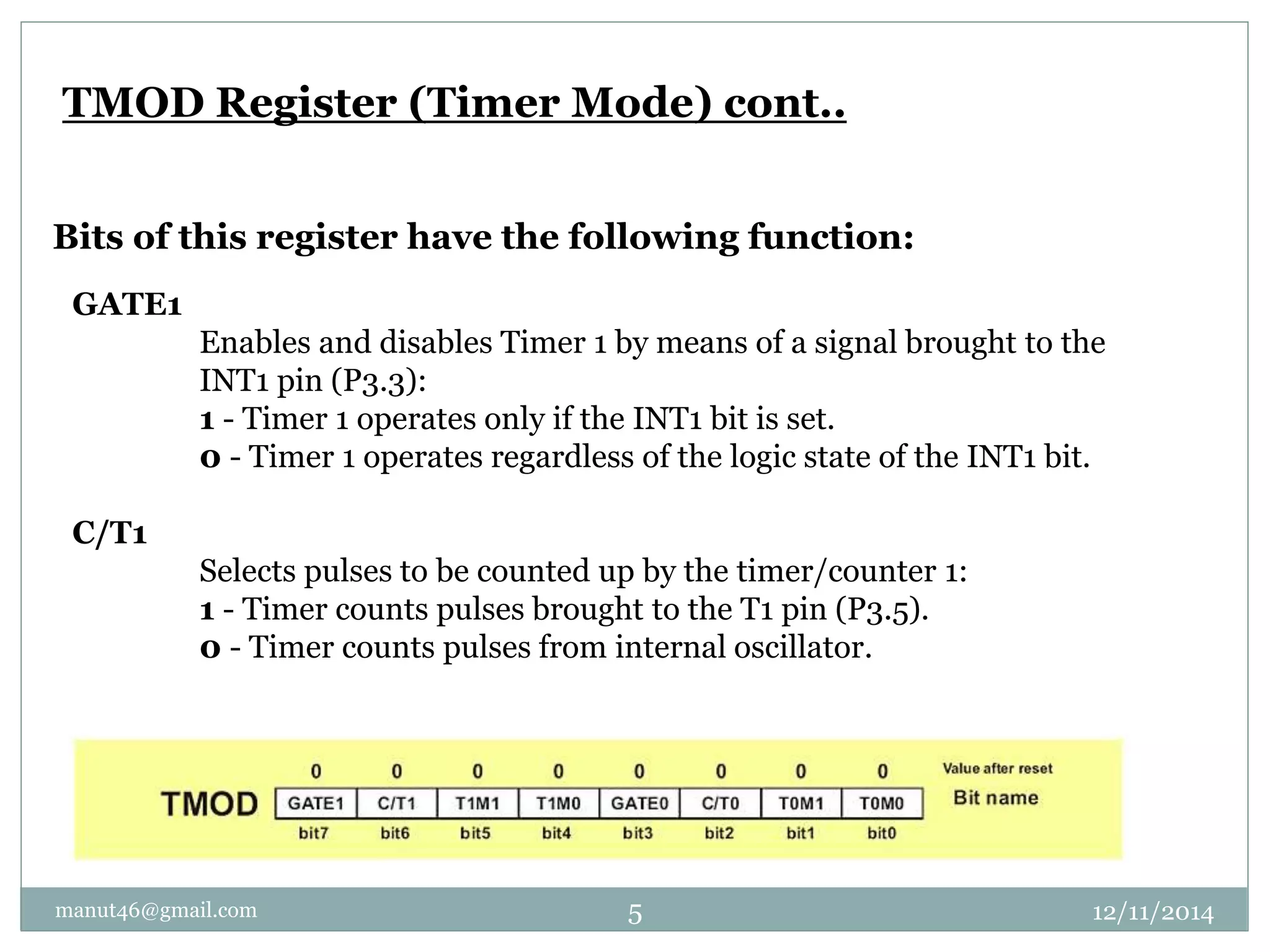
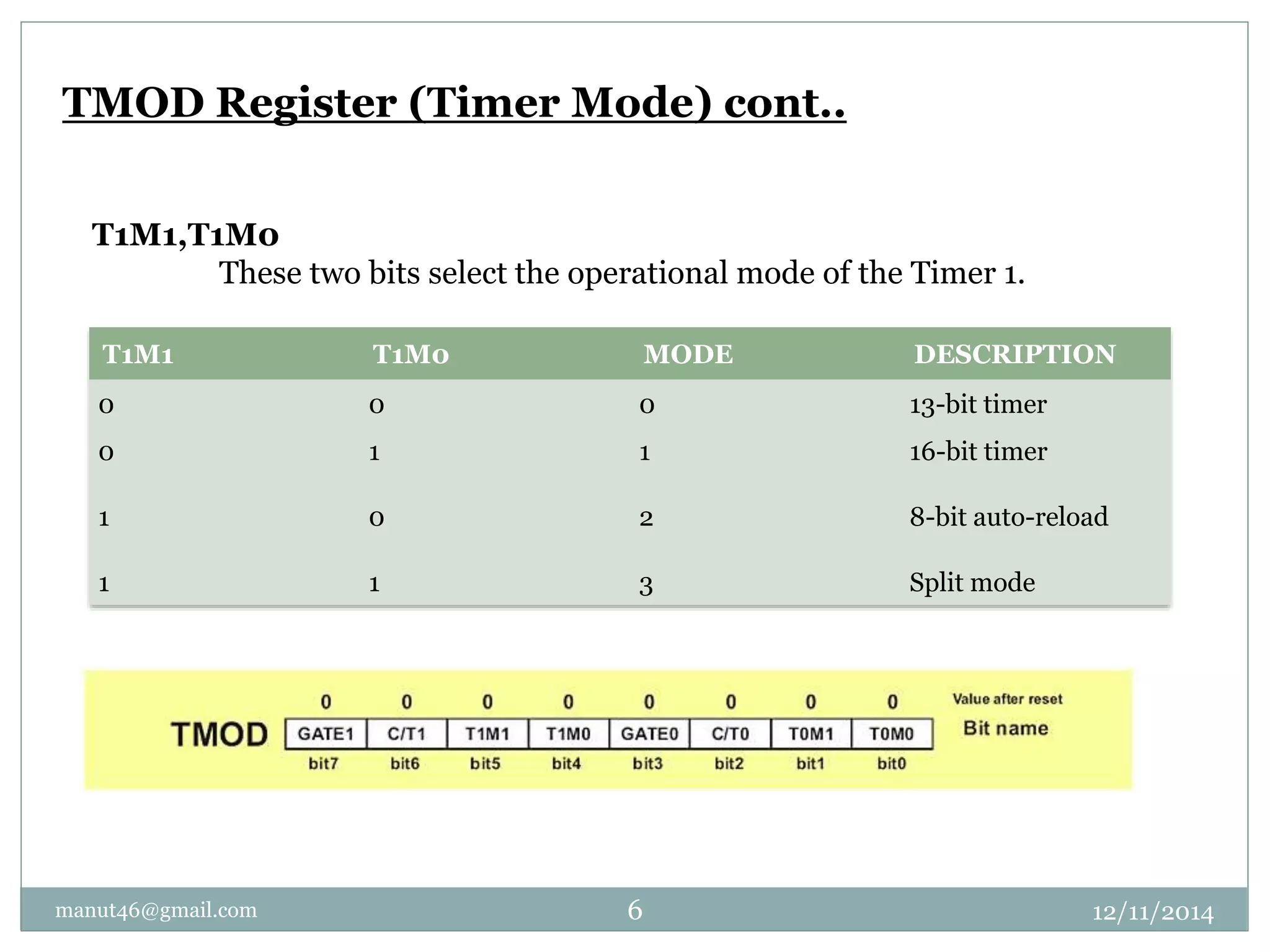
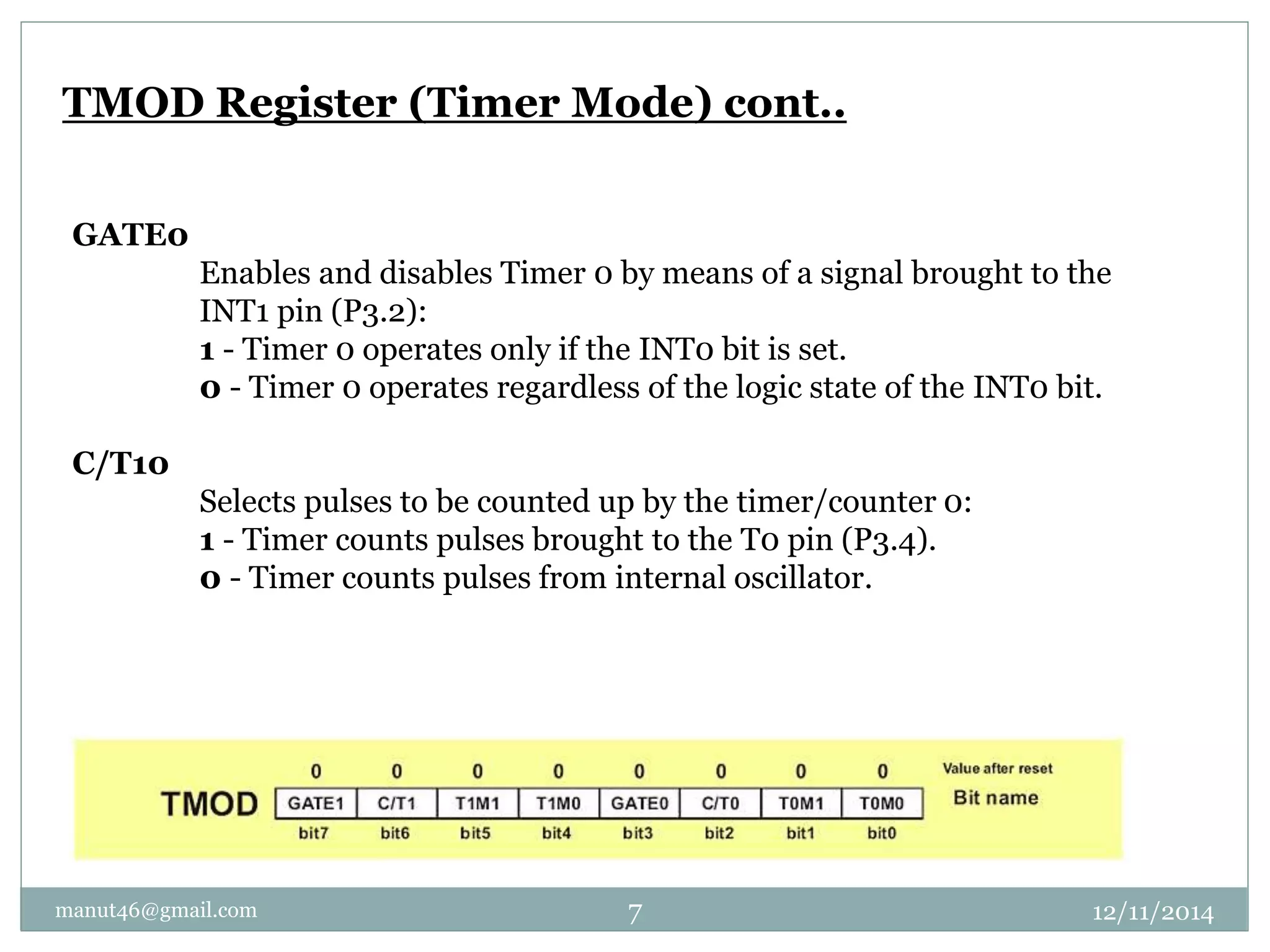
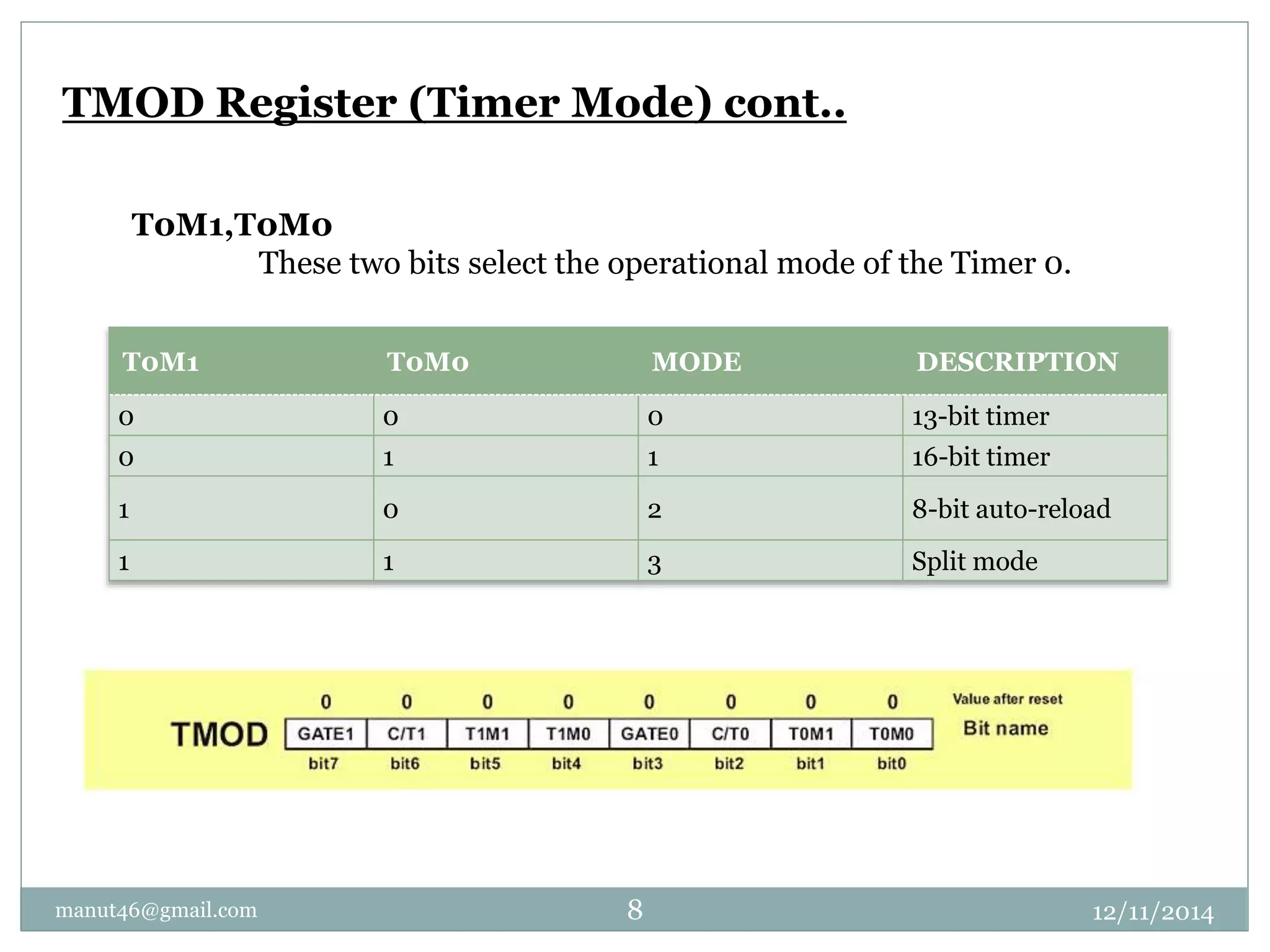
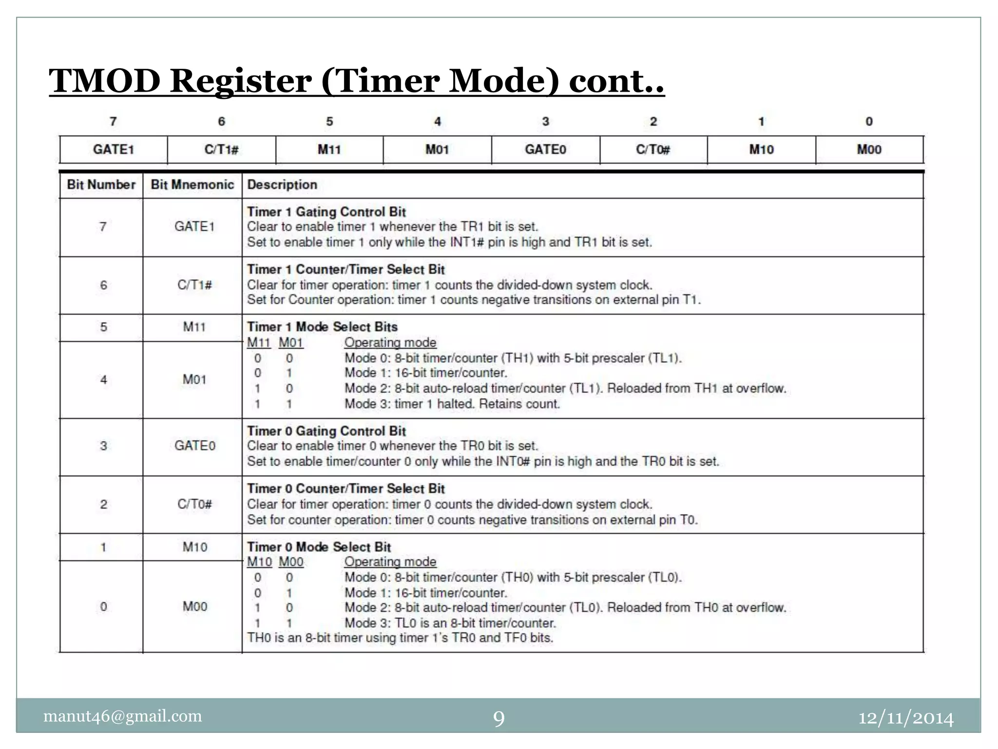
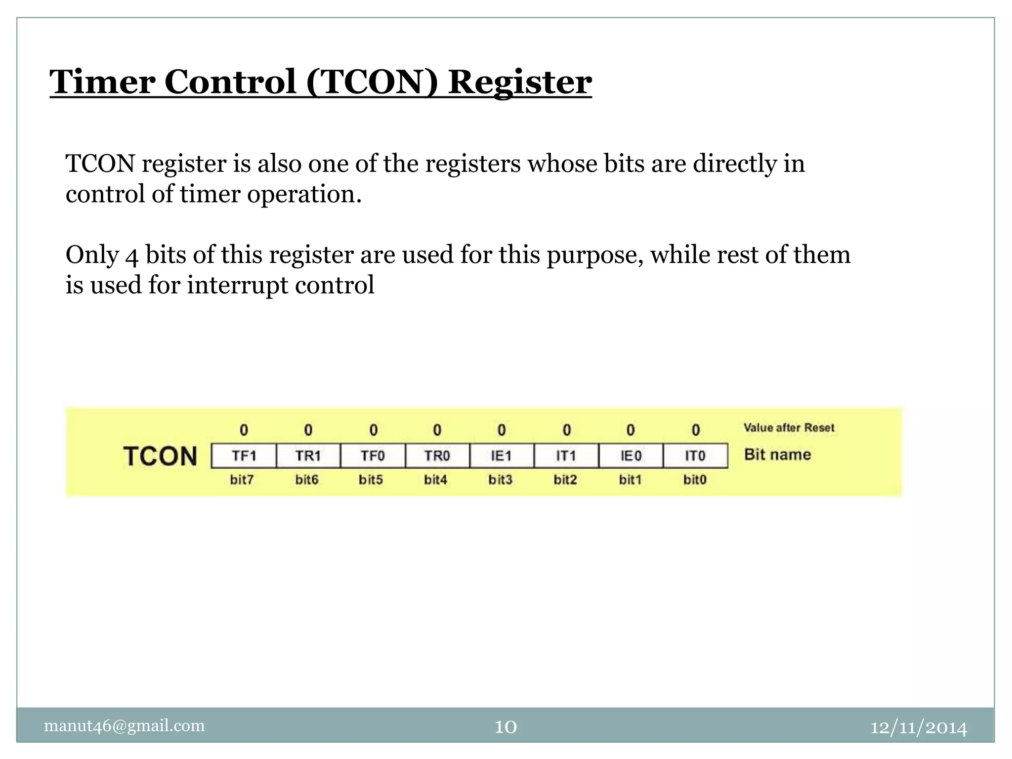
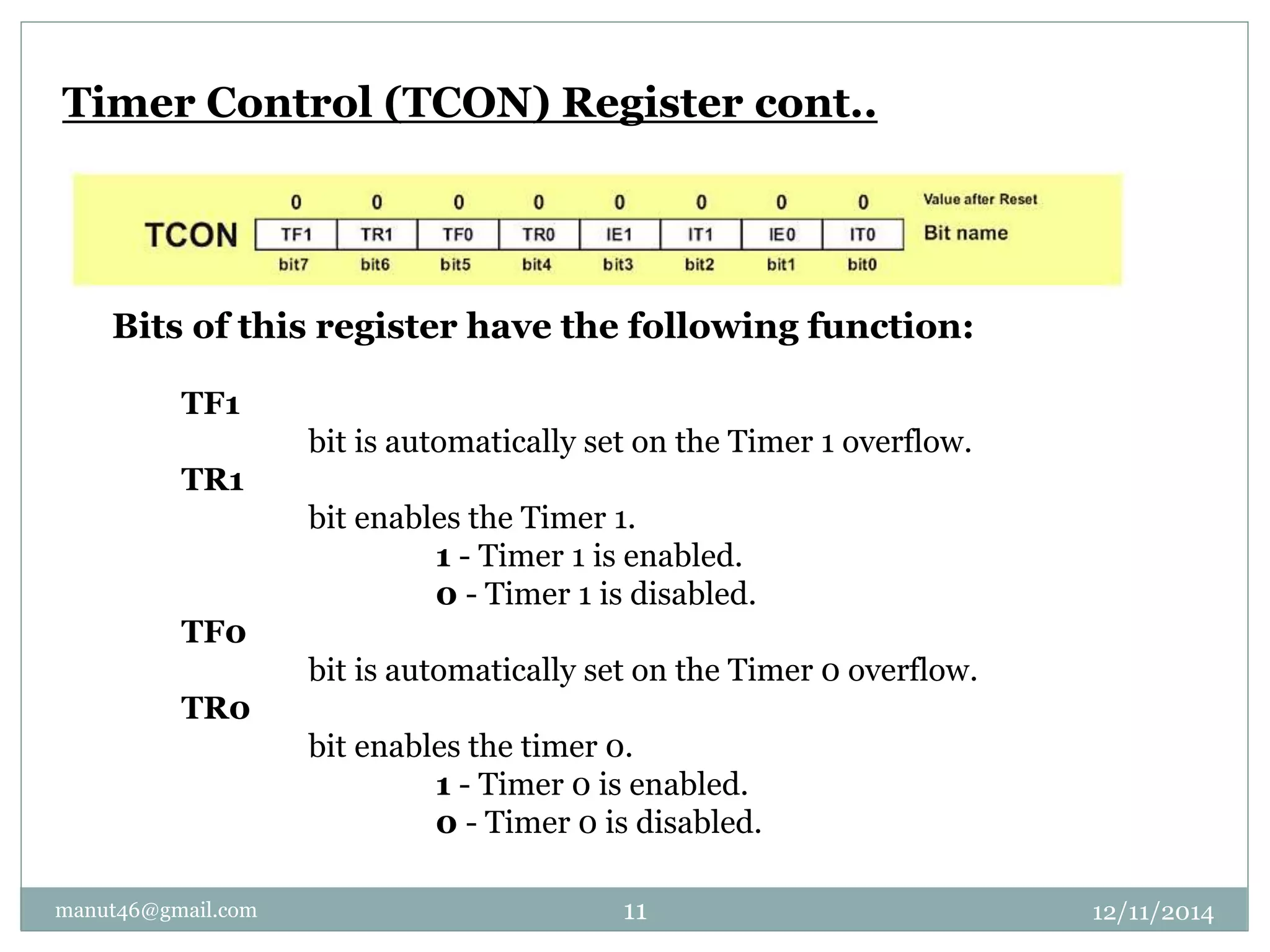
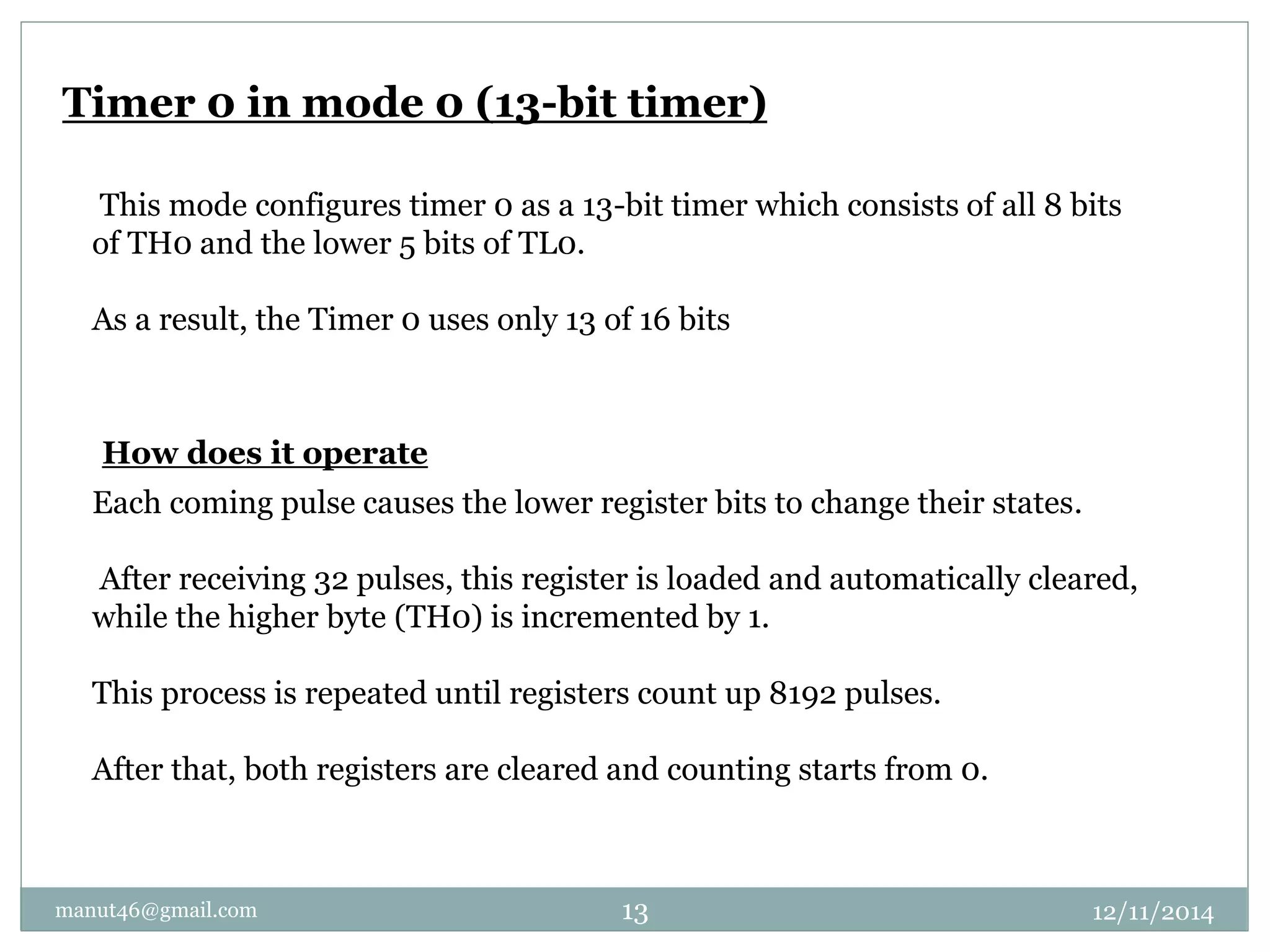
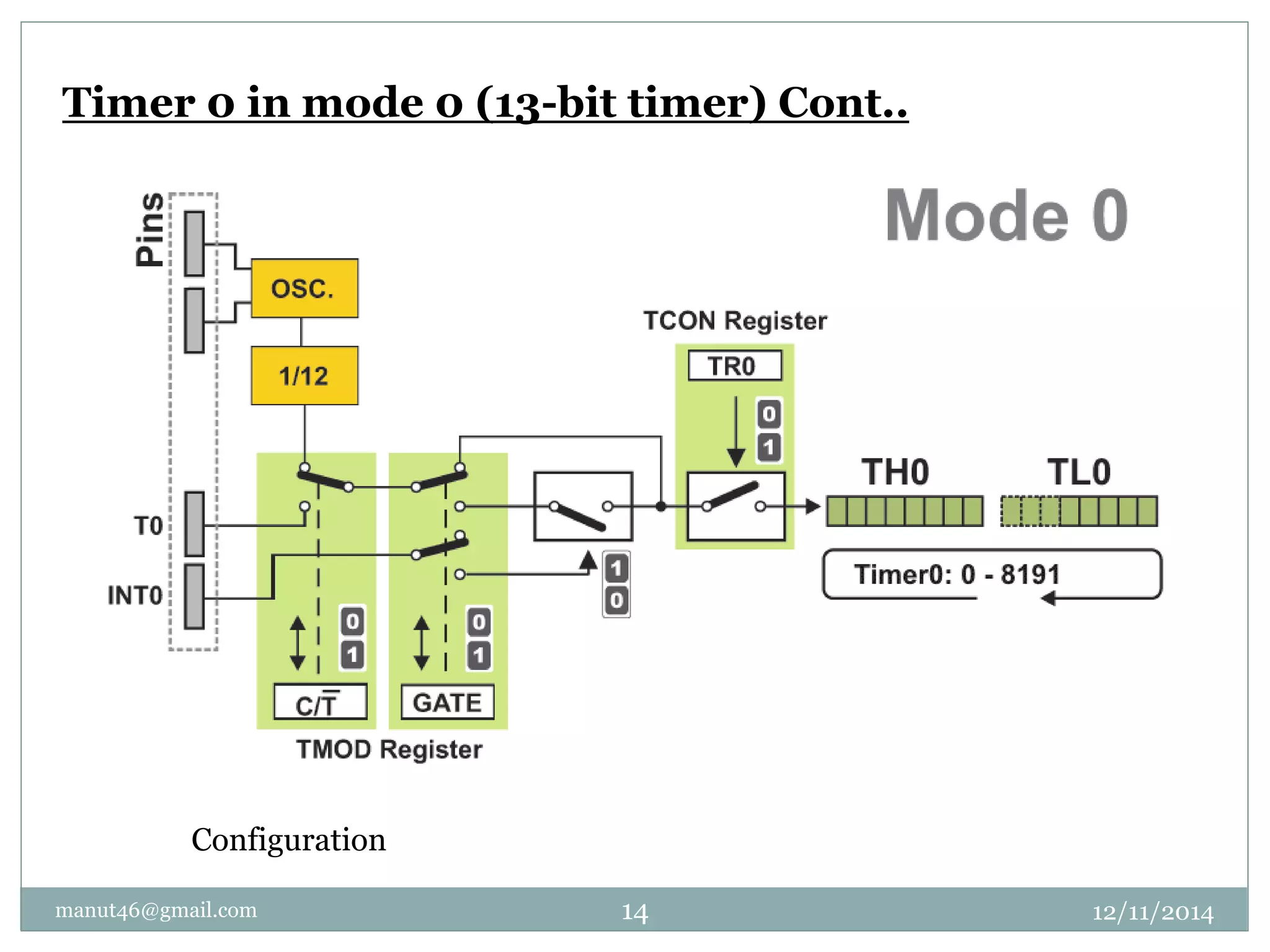
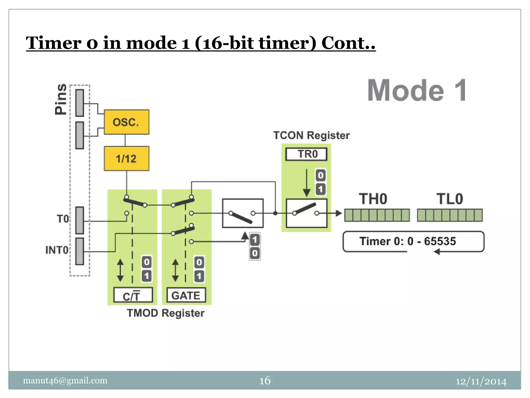
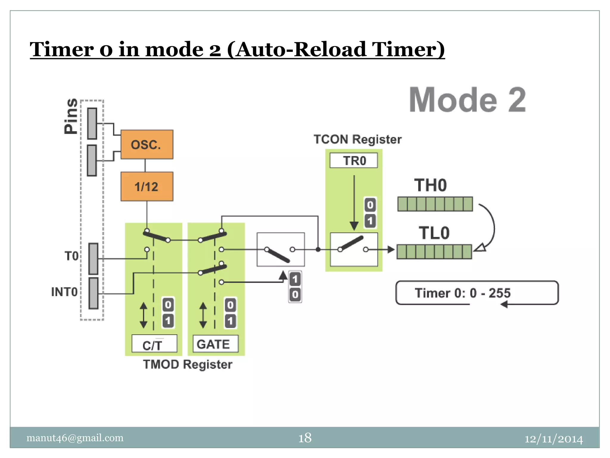

The document provides an overview of the timers and counters in the 8051 microcontroller, detailing two main timers (t0 and t1) and their functionalities, such as keeping time, counting events, and generating baud rates. It explains the operation of various registers including the TMOD and TCON registers that control the timers' modes and enable/disable functionalities. Additionally, it describes different operating modes for Timer 0, including 13-bit, 16-bit, auto-reload, and split modes.