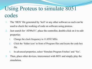
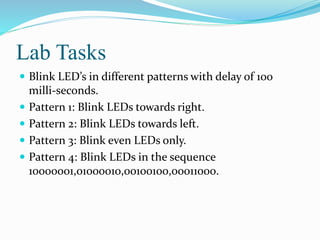
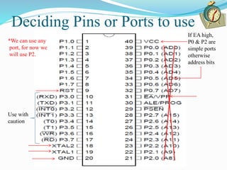
GENERATE PATTERNS ON LED USING 8051
Objectives of the Lab
 Interfacing LEDs using 8051 ports as output ports.
 Generating Delay using Delay Subroutine.
 Checking Working of Code on Proteus.
 Programming 8051 using Smart-PRO Burner.
Deciding Pins or Ports to use
Use with
caution
If EA high,
P0 & P2 are
simple ports
otherwise
address bits
*We can use any
port, for now we
will use P2.
Introduction to Assembly in 8051
 An assembly language instruction consists of four fields.
[Label:] mnemonic [operands] [;comments]
 Label is used to jump to a specific code location from any
other location.
 Mnemonic is used for opcode of command e.g. add, mov.
 Operands are used to mention the registers or constants
used by command.
 Comment field is used to make the code user friendly.
 Square brackets show that these fields are optional.
Review
Registers (Naming) Normally Used
Accumulator (A or ACC) Base (B)
Ports (P0,P1,P2,P3 & Px.y) PSW (For Flags & Register Banks)
R0,R1,…,R7 SP(Stack Pointer)
DPTR(Data Pointer) Timer Registers
Serial Port Registers Interrupt Registers
PCON (Power Control
Register)
IP (Instruction Pointer)
Legend:
* Frequently used
* Special Functions
* Occasionally
* Used automatically
Instructions used in this Lab
 MOV DEST,SOURCE
 mov p0,#10101001b
 mov p0,#0A9h
 mov p0,#169d or mov p0,#169
 JMP LABEL
 DJNZ REG,LABEL
 RL A
 RR A
 See instruction set for the details of above commands.
Algorithm to generate LED
patterns
Start
Send seq to
output
First Sequence
Next Sequence
Call Delay
*Controller Programs tend to run forever i.e. in the infinite loop.
mov a,#seq
mov p2,a
rr a
call delay
Review
Program Structure (Directives)
org 00h
.
.
.
call delay
.
.
.
delay: ;subroutine
.
.
.
ret
end
Delay subroutine:
delay:
mov r6,#2
dl1:
mov r7,#10
dl2: djnz r7,dl2 ; djnz r7,$
djnz r6,dl1
ret
Delay Calculation
delay:
mov r6,#x
dl1:
mov r7,#y
djnz r7,$
djnz r6,dl1
ret
1
1
2 * y * x
2
2
*Refer to instruction set for delays of individual commands
Delay= (2y+1+2)x+1+2 =(2y+3)x+3 machine cycles
 Putting in the values of x and y, we can calculate delay
in machine cycles and then we can calculate the time
by multiplying this by the time one machine cycle takes.
Generating Required Delay
1. We discussed that the above subroutine creates delay of (2y+3)x+3
machine cycles. To convert this delay into time, we need to replace
machine cycle by the time it takes.
2. For a 12 MHz crystal, 1mc = 1µs, and delay=(2y+3)x+3µs.
3. If we want to create delay of 100 milli-seconds, then
100ms=(2y+3)x+3µs, one equation, two unknown, assume some value
of ‘y’ and find out ‘x’.
4. If the above calculated values of ‘x’ and ‘y’ are used, one will be able to
generate delay of 100 ms, using a 12 MHz crystal.
*Calculate values of x and y for generating delay of 100 ms with XTAL=11.0592 MHz
Using Proteus to simulate 8051
codes
1. The ‘HEX’ file generated by ‘keil’ or any other software as such can be
used to check the working of code on software using proteus.
2. Just search for ‘AT89c51’, place the controller, double click on it to edit
properties
1. Change the clock frequency to 11.0592 MHz.
2. Click the ‘folder icon’ in front of Program files and locate the code hex
file.
3. In advanced properties, select ‘Simulate Program Fetches’ and ‘Yes’.
3. Then, place other devices, interconnect with 8051 and simply play the
simulation.
How to program a µC using
SmartPro 2008 (Programmer)
1. Connect your SmartPro 2008 Programmer to PC via
USB port and turn the device on using its adapter. Also,
place the µC carefully in the ZIF socket.
2. Locate and click ‘SmartPro 2008’ icon available on
desktop.
3. If it asks for the Programmer Select ‘Smart PRO 5000u’
and click demo.
*One must check, how to place different types of controller in the programmer.
How to program a µC using
SmartPro 2008 (Programmer)
4. Click ‘Select Device’ on the window or choose Device>Select or
press Ctrl+S.
1. In ‘Type’, select ‘MCU’
2. In ‘Manufacturer’, select ‘ATMEL’ , AT89Cxx.
3. In ‘Device’, select AT8951.
5. Now, select File>Open or press Ctrl+O, in ‘files of type’ select Intel
Hex and locate the ‘HEX’ file you want to program. Also, see if
buffer is loaded with the new ‘HEX’ file.
How to program a µC using
SmartPro 2008 (Programmer)
6. Now, there are a bunch of options that can be performed depending upon
the users needs.
1. F4 or Click ‘Read’: Reads a previous program already burned in the µC.
2. F5 or ‘Erase’: Erases the previous program in µC.
3. F6 or ‘Blank Check’: Verification if program is erased.
4. F7 or ‘Program’: Loads the *current HEX file in µC.
5. F8 or ‘Verify’: Verification if the program is properly loaded.
6. ‘Batch’: This option is used in Industry.
7. Spacebar or ‘Auto’: Performs all the steps from 2 to 5 in sequence.
7. Shortcut: Open SmartPro, slect device, locate hex file & press spacebar.
Debugging with µC
1. Unlike electronic circuits, the debugging with µC is different.
Firstly, there is software debugging and then there is hardware
debugging.
2. The software debugging includes the working of code.
3. The hardware debugging includes the working of code on
hardware and the devices interfaced.
4. Always perform µC experiment in three stages, test the µC IC and
generic board using led blinking, then verify the working of code
on Proteus software, then finally test the program on hardware.
Proteus Devices needed in this Lab
1. AT89c51
2. LED Bargraph
3. Resistor Pack
Lab Tasks
 Blink LED’s in different patterns with delay of 100
milli-seconds.
 Pattern 1: Blink LEDs towards right.
 Pattern 2: Blink LEDs towards left.
 Pattern 3: Blink even LEDs only.
 Pattern 4: Blink LEDs in the sequence
10000001,01000010,00100100,00011000.

Micro c lab2(led patterns)

  • 1.
    GENERATE PATTERNS ONLED USING 8051
  • 2.
    Objectives of theLab  Interfacing LEDs using 8051 ports as output ports.  Generating Delay using Delay Subroutine.  Checking Working of Code on Proteus.  Programming 8051 using Smart-PRO Burner.
  • 3.
    Deciding Pins orPorts to use Use with caution If EA high, P0 & P2 are simple ports otherwise address bits *We can use any port, for now we will use P2.
  • 4.
    Introduction to Assemblyin 8051  An assembly language instruction consists of four fields. [Label:] mnemonic [operands] [;comments]  Label is used to jump to a specific code location from any other location.  Mnemonic is used for opcode of command e.g. add, mov.  Operands are used to mention the registers or constants used by command.  Comment field is used to make the code user friendly.  Square brackets show that these fields are optional.
  • 5.
    Review Registers (Naming) NormallyUsed Accumulator (A or ACC) Base (B) Ports (P0,P1,P2,P3 & Px.y) PSW (For Flags & Register Banks) R0,R1,…,R7 SP(Stack Pointer) DPTR(Data Pointer) Timer Registers Serial Port Registers Interrupt Registers PCON (Power Control Register) IP (Instruction Pointer) Legend: * Frequently used * Special Functions * Occasionally * Used automatically
  • 6.
    Instructions used inthis Lab  MOV DEST,SOURCE  mov p0,#10101001b  mov p0,#0A9h  mov p0,#169d or mov p0,#169  JMP LABEL  DJNZ REG,LABEL  RL A  RR A  See instruction set for the details of above commands.
  • 7.
    Algorithm to generateLED patterns Start Send seq to output First Sequence Next Sequence Call Delay *Controller Programs tend to run forever i.e. in the infinite loop. mov a,#seq mov p2,a rr a call delay
  • 8.
    Review Program Structure (Directives) org00h . . . call delay . . . delay: ;subroutine . . . ret end
  • 9.
    Delay subroutine: delay: mov r6,#2 dl1: movr7,#10 dl2: djnz r7,dl2 ; djnz r7,$ djnz r6,dl1 ret
  • 10.
    Delay Calculation delay: mov r6,#x dl1: movr7,#y djnz r7,$ djnz r6,dl1 ret 1 1 2 * y * x 2 2 *Refer to instruction set for delays of individual commands Delay= (2y+1+2)x+1+2 =(2y+3)x+3 machine cycles  Putting in the values of x and y, we can calculate delay in machine cycles and then we can calculate the time by multiplying this by the time one machine cycle takes.
  • 11.
    Generating Required Delay 1.We discussed that the above subroutine creates delay of (2y+3)x+3 machine cycles. To convert this delay into time, we need to replace machine cycle by the time it takes. 2. For a 12 MHz crystal, 1mc = 1µs, and delay=(2y+3)x+3µs. 3. If we want to create delay of 100 milli-seconds, then 100ms=(2y+3)x+3µs, one equation, two unknown, assume some value of ‘y’ and find out ‘x’. 4. If the above calculated values of ‘x’ and ‘y’ are used, one will be able to generate delay of 100 ms, using a 12 MHz crystal. *Calculate values of x and y for generating delay of 100 ms with XTAL=11.0592 MHz
  • 12.
    Using Proteus tosimulate 8051 codes 1. The ‘HEX’ file generated by ‘keil’ or any other software as such can be used to check the working of code on software using proteus. 2. Just search for ‘AT89c51’, place the controller, double click on it to edit properties 1. Change the clock frequency to 11.0592 MHz. 2. Click the ‘folder icon’ in front of Program files and locate the code hex file. 3. In advanced properties, select ‘Simulate Program Fetches’ and ‘Yes’. 3. Then, place other devices, interconnect with 8051 and simply play the simulation.
  • 13.
    How to programa µC using SmartPro 2008 (Programmer) 1. Connect your SmartPro 2008 Programmer to PC via USB port and turn the device on using its adapter. Also, place the µC carefully in the ZIF socket. 2. Locate and click ‘SmartPro 2008’ icon available on desktop. 3. If it asks for the Programmer Select ‘Smart PRO 5000u’ and click demo. *One must check, how to place different types of controller in the programmer.
  • 14.
    How to programa µC using SmartPro 2008 (Programmer) 4. Click ‘Select Device’ on the window or choose Device>Select or press Ctrl+S. 1. In ‘Type’, select ‘MCU’ 2. In ‘Manufacturer’, select ‘ATMEL’ , AT89Cxx. 3. In ‘Device’, select AT8951. 5. Now, select File>Open or press Ctrl+O, in ‘files of type’ select Intel Hex and locate the ‘HEX’ file you want to program. Also, see if buffer is loaded with the new ‘HEX’ file.
  • 15.
    How to programa µC using SmartPro 2008 (Programmer) 6. Now, there are a bunch of options that can be performed depending upon the users needs. 1. F4 or Click ‘Read’: Reads a previous program already burned in the µC. 2. F5 or ‘Erase’: Erases the previous program in µC. 3. F6 or ‘Blank Check’: Verification if program is erased. 4. F7 or ‘Program’: Loads the *current HEX file in µC. 5. F8 or ‘Verify’: Verification if the program is properly loaded. 6. ‘Batch’: This option is used in Industry. 7. Spacebar or ‘Auto’: Performs all the steps from 2 to 5 in sequence. 7. Shortcut: Open SmartPro, slect device, locate hex file & press spacebar.
  • 16.
    Debugging with µC 1.Unlike electronic circuits, the debugging with µC is different. Firstly, there is software debugging and then there is hardware debugging. 2. The software debugging includes the working of code. 3. The hardware debugging includes the working of code on hardware and the devices interfaced. 4. Always perform µC experiment in three stages, test the µC IC and generic board using led blinking, then verify the working of code on Proteus software, then finally test the program on hardware.
  • 17.
    Proteus Devices neededin this Lab 1. AT89c51 2. LED Bargraph 3. Resistor Pack
  • 18.
    Lab Tasks  BlinkLED’s in different patterns with delay of 100 milli-seconds.  Pattern 1: Blink LEDs towards right.  Pattern 2: Blink LEDs towards left.  Pattern 3: Blink even LEDs only.  Pattern 4: Blink LEDs in the sequence 10000001,01000010,00100100,00011000.