Download to read offline


![Power Control Register(PCON)
SMOD used decide the baud rate in serial port operating modes
1,2,3
In Mode 2:
If SMOD=0 baud rate=1/64 of the oscillator frequency
If SMOD=1 Baud rate=1/32 of the oscillator frequency.
In Mode 1 & 3: baud rate depends on SMOD and timer-1 overflow
rate.Baud rate(mode 1 or 3)=(2^SMOD/32)*timer-1 overflow rate.
Timer-1 auto reload mode.
Timer-1 over flow rate= oscillator frequency/12*[256-(TH1)^2]
TH1 reload count value -8 bit in higher order timer-1 count register.](https://image.slidesharecdn.com/serialcommunicationin8051-241217181152-a66c0ea5/85/Serial-communication-in-8051-microcontroller-pptx-5-320.jpg)
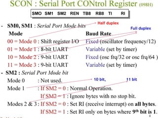

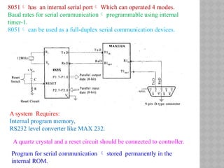
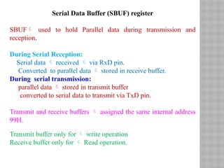
The document discusses serial communication in the 8051 microcontroller, which includes an internal serial port capable of four modes and programmable baud rates using timer-1. It details the components required for operation, such as memory, level converters, and how data can be transmitted and received in both serial and parallel formats. The document also covers the use of buffers for data storage during transmission and reception, as well as baud rate configurations based on specific operating modes.