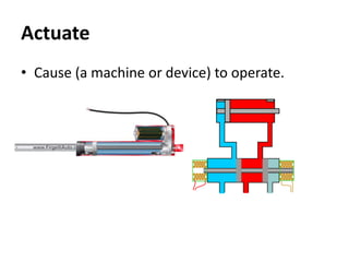
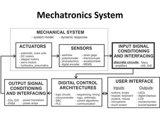
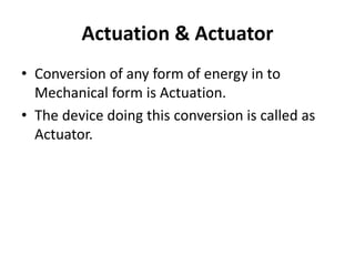
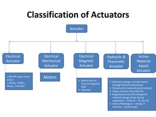
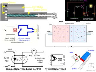
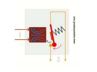
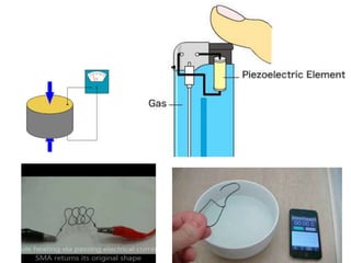
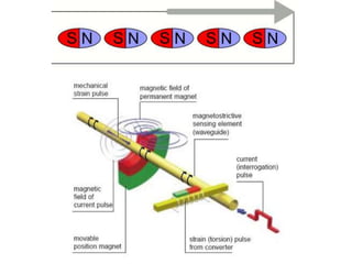
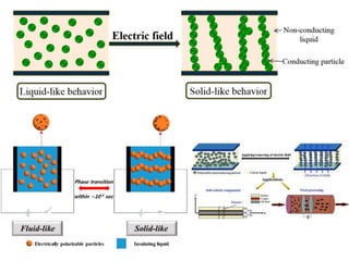
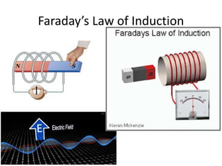
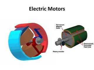
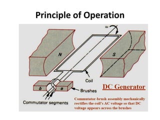
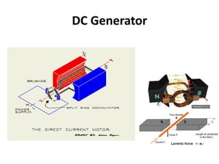
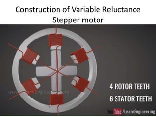
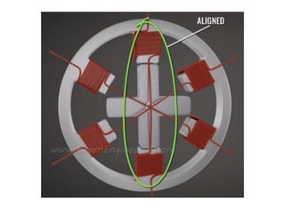
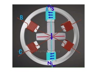
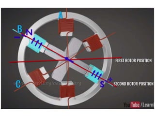
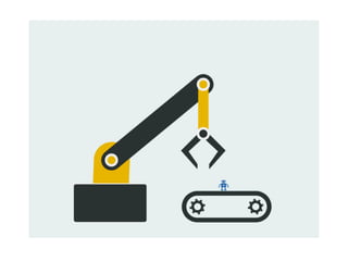
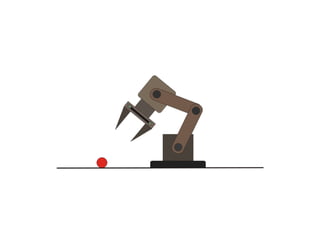
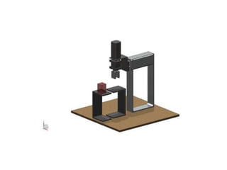
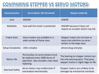
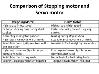
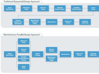
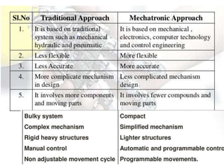
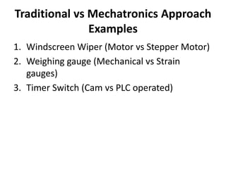
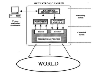
Unit 5
Actuators and Mechatronic system
design
Actuate
• Cause (someone) to act
in a particular way;
motivate.
Actuate
• Cause (a machine or device) to operate.
Mechatronics System
Actuation & Actuator
• Conversion of any form of energy in to
Mechanical form is Actuation.
• The device doing this conversion is called as
Actuator.
Classification of Actuators
Actuator
Electrical
Actuator
> ON OFF type control
action
> Diodes, TRIACs,
Relays, Transistor
Electrical
Mechanical
Actuator
Motors
Electrical
Magnetic
Actuator
 Motion due to
internal magnetic
field
 Solenoid
Hydraulic &
Pneumatic
Actuator
Active
Material
based
Actuator
 Material undergo transformation
through Physical interactions
 Piezoelectric materials (small motion)
 Shape memory alloy (Nitinol)
 Magnetoastricive (Ferromagnetic
material change shape during
magnetism – Terfenol – Tb, Dy, Fe)
 Electro Rheological – change in
viscosity – Liquid to gell
Faraday’s Law of Induction
Electric Motors
Principle of Operation
DC Generator
00 Position (DC Neutral Plane)
900 Position (DC)
1800 Position (DC)
2700
Position
(DC)
00 Position (DC
Neutral Plane)
DC Motor
Schematic diagram of DC Motor
DC motors
DC Motor
(Physical Cut Section)
Cutaway view of a dc motor Stator with poles visible.
segments
brushes
Rotor of a dc motor.
AC Generator
AC motor Classification
Induction Motor
Squirrel cage Induction Motor
Synchronous Motor
Stepper motor
• The motor converts electrical pulse into
discrete mechanical movements.
• 2°, 2.5°, 5°, 7.5°, 15° rotations per input
electrical pulse.
• Speed of motor shaft ∝ Frequency of input
pulses.
Stepper Motor
Basic parts of any Motor
Properties of stepper motor
• Open – Loop control system
• Rotates in both direction
• Self locking when rotor is stationary
• Excellent positional accuracy
Types of Stepper motor
1. Permanent magnet stepper motor
2. Variable reluctance stepper motor
3. Hybrid stepper motor
Permanent Magnet Stepper motor
• No teeth
Construction of Permanent magnet
Stepper motor
No teeth in permanent magnet stepper motor
No. of Poles ∝ Steps
Working of Permanent Magnet
Stepper motor
Construction of Variable Reluctance
Stepper motor
• Multi tooth – Soft
iron core.
• No. of poles on rotor
< No. of poles on
stator
• Stator coil windings –
DC current – poles
get magnetized.
Construction of Variable Reluctance
Stepper motor
Construction of Variable Reluctance
Stepper motor
Half Step in VR stepper motor
Variable reluctance Stepper motor
Hybrid Stepper motor
• Combination of VR & PM SM
• Rotor & stator are multi toothed.
Hybrid Stepper motor
Construction of Hybrid Stepper Motor
Half Aligned
Half Aligned
Unaligned
Fully Aligned
Construction of Hybrid Stepper Motor
Working of Hybrid Stepper Motor
Step modes of Stepper motor
• Full step mode – 1.8 step
• Half step mode – 0.9 step
• Microstep mode – 1/256 steps or 50,000 steps
per revolution
Servo motor
• Rotation for certain angle for long period of
time.
• Special type of motor which is automatically
operated up to certain limit for a given
command with help of error-sensing feedback
to correct the performance.
Types of Servo motor
1. DC Servo motor
2. AC servo motor
DC Servo motor
Construction of Servo Motor
Working principle
Working principle
AC servo motor
Construction of AC Servo motor
Working Principle
Working Principle
Advantages & Disadvantages of
Servo motor
• Closed loop
• High efficiency up to 90% at light loads
• High output relative to motor size and weight
• AC servo motor is low cost
• No linear characteristics
• Complex design, Needs encoder
• DC servo motor is costly but widely used
• Brushes wears out to 2000hrs
• Services and maintenance required.
Comparison of Stepping motor and
Servo motor
First half of this unit ends here
Stages in designing mechatronics
system
Mechatronics design approach
3 Design Stages
1. Conceptual design
2. Embodiment design
3. Production Design Cycle
• Initiating design – potential solution –
best concept
• Highly creative process & requires
coordination
• Consists of:
– Customer need identification
– Problem definition (Goal)
– Gathering Information (Literature Survey)
– Concept generation
– Concept selection
Stage 1: Conceptual design
• Preliminary design – ‘skeleton’
• After this stage, only minor design
modification
• Consists of:
– product architecture – subsystem and
its relation
– configuration design of part and components
– mathematical modeling and simulation
– sensors and actuators selection
– controller design
Stage 2: Embodiment design
• Prototyping
– approximation of a product
– Proof of concept
– E.g sketch, model, 3D drawing or fully
functional product
• Stage 3: Production
Stage 2: Embodiment design
• What World Think Of Indians?
Traditional vs Mechatronics Approach
Examples
1. Windscreen Wiper (Motor vs Stepper Motor)
2. Weighing gauge (Mechanical vs Strain
gauges)
3. Timer Switch (Cam vs PLC operated)
Traditional vs Mechatronics Approach
Examples
1.Windscreen Wiper
(Motor vs Stepper
Motor)
2. Weighing gauge (Mechanical vs Strain
gauges)
3. Timer Switch (Cam vs PLC operated)
Windscreen wiper
Traditional vs Mechatronics Approach
Examples
1. Windscreen Wiper (Motor vs Stepper Motor)
2.Weighing gauge
(Mechanical vs Strain
gauges)
3. Timer Switch (Cam vs PLC operated)
Weighing scale Traditional approach
Weighing scale Mechatronic approach
Block diagram of Electronic Weighing
machine
Whetstone
bridge
(Load cell or
strain gauge
connected)
Amplifier ADC
Display
device
(LED, LCD)
Display driver
Power supply
Case Studies
1. Pick and Place Robot
2. Engine Management System
3.Automatic Car park barrier
Case Studies
1. Pick and Place
Robot
2. Engine Management System
3.Automatic Car park barrier
Pick and Place robot
-
Before understanding the working of
Pick and place Robot
• Microprocessor, Microcontroller
• DCV – Direction Control Valve in Hydraulics
and Pneumatics
• TRIAC
Before understanding the working of
Pick and place Robot
•Microprocessor,
Microcontroller
• DCV – Direction Control Valve in Hydraulics
and Pneumatics
• TRIAC
Before understanding the working of
Pick and place Robot
• Microprocessor, Microcontroller
•DCV – Direction Control
Valve in Hydraulics and
Pneumatics
• TRIAC
Understanding Way (Ports)
and Position (Directions)
Simple Push button actuation
4/2 way DCV
Name the DCV?
5/2 Way DCV
5/3 way DCV
Before understanding the working of
Pick and place Robot
• Microprocessor, Microcontroller
• DCV – Direction Control Valve in Hydraulics
and Pneumatics
•TRIAC
TRIAC
• Triac used as a simple static AC
power switch providing an “ON”-
“OFF” function similar in
operation to the previous DC
circuit.
Diode
Covalent Bond
Doping
Doping
Barrier potential
Diode
Diode
Transistor
Silicon Controlled Rectifier (SCR)
Physical Construction of TRIAC
Opto-Triac
• Photodiode or Photo Transistor
Pick and Place Robot
• Movements in Pick and Place
Robot:
– Clockwise & anticlockwise of
robot unit on its base
– Linear movement (extension or
contraction)
– Up & down movement of arm
– Open & close movement of
gripper
Pick and Place Robot
• Robot consists of:
1. Rover – main body
2. End effectors or Grippers
3. Sensors
4. Actuators
5. Controller
Microcontroller
Display
(LCD)
Teach pendent
(PLC)/ Keypad
Electro-
Pneumatics
Base actuator
(Clockwise &
anticlockwise)
Basic Block diagram for Pneumatically actuated Pick and Place Robot
Electro-
Pneumatics
Electro-
Pneumatics
Electro-
Pneumatics
Up & Down
movement of Arm
Extension &
Retention of Arm
Open & Close of
End
Effector/Gripper
Advancement in Pick & Place Robot
Applications of Pick & Place Robot
• Defence applications
• Industrial application
• Medical application
Case Studies
1. Pick and Place Robot
2. Engine
Management
System
3.Automatic Car park barrier
EMS
EMS
• ECU
• Throttle position sensor
– Throttle opening and force applied by the driver
– Controls fuel delivery & spark ignition
– Potentiometer and Hall effect sensor
• EGO – Exhaust gas Oxygen sensor
– Amt of Oxygen in exhaust system
– Lambda (l) Sensor
– ZrO2/ Pt electrodes
EMS
• MAP
– Vacuum in manifold
– Piezoelectric & capacitive sensor
• Temp sensor
– Cabin, Engine, etc
– Activates cooling fan
– Thermistor, Thermodiode, thermocouple
EMS
• EGR
– Low HC level in exhaust
• MAF sensor
– Engine load to spray right amt of fuel
– Hot wire airflow sensor (Anemometer)
• Knock sensor
– Unburnt fuel inside will before ignition starts
– Piezoelectric sensor
Case Studies
1. Pick and Place Robot
2. Engine Management System
3.Automatic Car
park barrier
Before understanding a Car Park
barrier
• Basic knowledge of PLC ladder diagram
Relay Operation
Ladder diagram used to write PLC
program
Ladder Logic
Ladder diagram
Traditional vs Mechatronics Approach
Examples (Contd..)
1. Windscreen Wiper (Motor vs Stepper Motor)
2. Weighing gauge (Mechanical vs Strain gauges)
3.Timer Switch
(Cam vs PLC
operated)
Mechatronics Approach
Automatic car park barrier
Automatic Car park barrier
(Coin operated)
Automatic Car park barrier
(Coin operated)
Automatic Car park barrier
(PLC - Coin operated)
Ladder diagram for Automatic Car
park barrier
Unit 5 ends here
Basic ideas about Part-C questions
Autonomous Mobile Robot (AGV)
Driverless Trains
Pallet Trucks
Unit Load Carrier
Automated Guided Vehicle
Locomotion
• Legged
• Snake
• Free-floating
• Wheeled
• Swimming
• Flying
• Swarm
Sensory perception & Knowledge
representation
• Knowledge representation
– Ability to model the world
– Recognize certain object in an environment
• AGV – communicate to humans about the
location of victims and hazards
• IoT – use Maps
Planning, Autonomy and
Collaboration
Factors
• Dimensions, mass of objects to be handled
• Actuators
• Power source
• Range of gripping force
• Positioning
• Environment
• Protection from hazards
Application of AGV
• Nuclear Accident cleanup
• Planetary exploration
• Mail delivery
Wireless Surveillance Balloon
• Image sensors
• Thermal sensors
• Audio sensors
• Location sensors
• Altitude sensors
• A compass and
• Motion sensors
• Aerostats – LTA (Lighter than Air- He, H) balloons.
Applications
• Border security
• Coastal surveillance
• Platform for telecommunication, TV, radio
transmission
• Aerial platform for Scientific instrument
testing
• Aerial platform for Weather prediction
• Terrestrial mapping
Elevator system
s
Mechatronic System Examples
(Maybe asked as Part C in Univ exam)
• Robots
• Printer System (3D)
• Photocopying machines
• Bar code reader
• Any Home appliances (TV,
CD player, remote, Fridge,
Air conditioner, Sewing
machines etc.,)
• Automatic door systems
• Automatic security system
• ABS
• Fuel injection systems
• Sorting and packaging
systems (Packing
machines)
• CNC
• Heat-seeking missiles
• CMM
• ATM
• Medical field (magnetic
resonance, ultrasonic
probes, arthroscopic
devices)
• Digital thermostat
Unit 5 - Actuators and Mechatronics system Design, Case Study1.pptx

Unit 5 - Actuators and Mechatronics system Design, Case Study1.pptx