SlideShare a Scribd company logo
Aim:
To study the sinusoidal steady-state response of the given RLC circuit which
can be used in a series bandpass filter.
Software Required:
LTspice software
Theory & Circuit Diagram:
The Series RLC circuit is shown in the above figure. The RLC series circuit can
be used as a series bandpass filter by placing a series LC circuit in series with
the load resistor. In the series RLC circuit, larger reactance determines the net
reactance of the circuit.
If XL > XC the circuit behaves like an inductive circuit and the current lags
the voltage and if XC > XL, the circuit behaves like a capacitive circuit and the
Sinusoidal Steady State Response of RLC circuit
(Series Band pass filter using passive components)
current leads the voltage. The magnitude and Phase angle of the current, I in
the series RLC circuit is obtained using the following equation,
 
2
2
L C
V V
I
Z R X X
 
 
 
1
tan L C
X X
R



For RLC circuit with R= 10 Ω, L= 1mH, C= 1 μF and Vm = 100 V, f = 50 Hz, XL =
ωL = 2ΠfL = 0.314 Ω, XC = (1/ωC) = (1/ 2ΠfC) = 3184 Ω, Im = 0.0314 A, Φ =
89.82°.
In this example, since XC > XL, Current leads the voltage.
Procedure:
1. Open LTspice. Go to File New Schematic.
2. On the File Menu, click on Edit Component.
3. Place the voltage sources, resistor, inductor , capacitor and ground on to
schematic and make necessary connections as shown in the Figure.
4. As shown in the figures below, Right click on the voltage source V1 and click
Advanced option and then Select SINE (Voffset Vamp Freq Td Theta Phi
Ncycles) and Set the values as (DC offset = 0, Amplitude =100, Freq = 50).
5. As shown in the figure below, Right click on the resistor, inductor and
capacitor and set the value as 10 Ω, 0.001 H and 1 μF respectively
6. Go to Edit → SPICE analysis. Set the type of sweep to Linear, Number of
points to 100 and start and stop frequency to 50 each in the AC Analysis
command as shown in the figure below and run the simulation. (run symbol
on the menu bar).
7. Observe the peak value of the current and phase angle from the obtained
output window below and note it in the “Theoretical Value” column of the
observation table.
8. For waveforms: Go to Edit → SPICE analysis. Set the stop time to 40ms in
Transient command as shown in the figure below and run the simulation.
(run symbol on the menu bar).
9. To view the results, right click → Add Trace → Select V (<<input node>>)
and I (L1).
10. Observe the waveforms, change the appropriate colors for proper
visibility using color preferences and control panel tool. Sample figure
shown below.
Observation table:
S. No. Parameter Theoretical Value Observed Value
1. I (Peak value)
31.41mA 31.417026mA
2. Phase angle
89.82 89.82
Waveforms:
Result & Inferences:
Thus, a series RLC circuit has been designed and implemented in LTspice
software, and the current amplitude and phase angle is observed as 0.0314 A
and 89.82° respectively which is matching with Theoretical Values. From the
waveforms, it is also observed that the current leads the voltage.
Practical Applications:
The three circuit elements, R, L, and C can be combined in several different
topologies by connecting them in series or parallel. RLC circuits have many
applications as follows:
 Variable tuned circuit
 Filters - Band-pass filter, Band-stop filter, Low-pass filter or High-pass
filter
 Oscillator
 Voltage multiplier
 Pulse discharge circuit
Course Outcome:
CO2. Analyze AC power circuits and networks, its measurement and safety
concerns
CO6. Design and conduct experiments to analyze and interpret data
Student Learning Outcomes (SLO):
SLO1. Having an ability to apply mathematics and science in engineering
applications
SLO9. Having problem-solving ability- solving social issues and engineering
problems

More Related Content

What's hot

Lecture 7 modelling-of__real_world_systems
Lecture 7 modelling-of__real_world_systemsLecture 7 modelling-of__real_world_systems
Lecture 7 modelling-of__real_world_systems
Saifullah Memon
 
Lecture 2 ME 176 2 Mathematical Modeling
Lecture 2 ME 176 2 Mathematical ModelingLecture 2 ME 176 2 Mathematical Modeling
Lecture 2 ME 176 2 Mathematical Modeling
Leonides De Ocampo
 
Lecture 6 modelling-of_electrical__electronic_systems
Lecture 6 modelling-of_electrical__electronic_systemsLecture 6 modelling-of_electrical__electronic_systems
Lecture 6 modelling-of_electrical__electronic_systems
Saifullah Memon
 

What's hot (18)

CONTROL SYSTEMS PPT ON A UNIT STEP RESPONSE OF A SERIES RLC CIRCUIT
CONTROL SYSTEMS PPT ON A UNIT STEP RESPONSE OF A SERIES RLC CIRCUIT CONTROL SYSTEMS PPT ON A UNIT STEP RESPONSE OF A SERIES RLC CIRCUIT
CONTROL SYSTEMS PPT ON A UNIT STEP RESPONSE OF A SERIES RLC CIRCUIT
 
Growth of current R-L and R-C Series circuit
Growth of current R-L and R-C Series circuitGrowth of current R-L and R-C Series circuit
Growth of current R-L and R-C Series circuit
 
236793460 ee6361-electric-circuit-lab-docx
236793460 ee6361-electric-circuit-lab-docx236793460 ee6361-electric-circuit-lab-docx
236793460 ee6361-electric-circuit-lab-docx
 
Dsp manual
Dsp manualDsp manual
Dsp manual
 
Power System Analysis and Design
Power System Analysis and DesignPower System Analysis and Design
Power System Analysis and Design
 
symmetrical component of power system
symmetrical component of power systemsymmetrical component of power system
symmetrical component of power system
 
FAULT ANALYSIS AND FAULT MATRIX DEVELOPMENT
FAULT ANALYSIS  AND  FAULT MATRIX DEVELOPMENTFAULT ANALYSIS  AND  FAULT MATRIX DEVELOPMENT
FAULT ANALYSIS AND FAULT MATRIX DEVELOPMENT
 
Symmetrical components
Symmetrical componentsSymmetrical components
Symmetrical components
 
Resonant Response of RLC Circuits
Resonant Response of RLC Circuits Resonant Response of RLC Circuits
Resonant Response of RLC Circuits
 
ECNG 3015 Industrial and Commercial Electrical Systems
ECNG 3015   Industrial and Commercial Electrical SystemsECNG 3015   Industrial and Commercial Electrical Systems
ECNG 3015 Industrial and Commercial Electrical Systems
 
Lecture 7 modelling-of__real_world_systems
Lecture 7 modelling-of__real_world_systemsLecture 7 modelling-of__real_world_systems
Lecture 7 modelling-of__real_world_systems
 
Lecture 2 ME 176 2 Mathematical Modeling
Lecture 2 ME 176 2 Mathematical ModelingLecture 2 ME 176 2 Mathematical Modeling
Lecture 2 ME 176 2 Mathematical Modeling
 
Lecture 6 modelling-of_electrical__electronic_systems
Lecture 6 modelling-of_electrical__electronic_systemsLecture 6 modelling-of_electrical__electronic_systems
Lecture 6 modelling-of_electrical__electronic_systems
 
Low pass filter and Integrator
Low pass filter and IntegratorLow pass filter and Integrator
Low pass filter and Integrator
 
Symmetrical component
Symmetrical componentSymmetrical component
Symmetrical component
 
Series and parallel resonators
Series and parallel resonatorsSeries and parallel resonators
Series and parallel resonators
 
Symmetrical components
Symmetrical componentsSymmetrical components
Symmetrical components
 
Synthesis of unsymmetrical phasors from their symmetrical components
Synthesis of unsymmetrical phasors from their symmetrical componentsSynthesis of unsymmetrical phasors from their symmetrical components
Synthesis of unsymmetrical phasors from their symmetrical components
 

Similar to Exp4

Electric Circuits LabInstructor -----------Serie.docx
Electric Circuits LabInstructor  -----------Serie.docxElectric Circuits LabInstructor  -----------Serie.docx
Electric Circuits LabInstructor -----------Serie.docx
pauline234567
 
November 21, 20131How a Diode WorksA diode is an electrica.docx
November 21, 20131How a Diode WorksA diode is an electrica.docxNovember 21, 20131How a Diode WorksA diode is an electrica.docx
November 21, 20131How a Diode WorksA diode is an electrica.docx
henrymartin15260
 
Assignment 1 Description Marks out of Wtg() Due date .docx
Assignment 1  Description Marks out of Wtg() Due date .docxAssignment 1  Description Marks out of Wtg() Due date .docx
Assignment 1 Description Marks out of Wtg() Due date .docx
fredharris32
 
Tennessee State University College of Engineering, Tec.docx
Tennessee State University College of Engineering, Tec.docxTennessee State University College of Engineering, Tec.docx
Tennessee State University College of Engineering, Tec.docx
mehek4
 
Electric Circuits Lab Series RC Circuits Phase Angle, Phase Lag.docx
Electric Circuits Lab Series RC Circuits Phase Angle, Phase Lag.docxElectric Circuits Lab Series RC Circuits Phase Angle, Phase Lag.docx
Electric Circuits Lab Series RC Circuits Phase Angle, Phase Lag.docx
pauline234567
 
Pulse amplitude modulation
Pulse amplitude modulationPulse amplitude modulation
Pulse amplitude modulation
Vishal kakade
 
Electric Circuits LabInstructor- -----------Parallel ResonanceStudent.docx
Electric Circuits LabInstructor-  -----------Parallel ResonanceStudent.docxElectric Circuits LabInstructor-  -----------Parallel ResonanceStudent.docx
Electric Circuits LabInstructor- -----------Parallel ResonanceStudent.docx
rosaliaj1
 
Bai thi nghiem_linear_circuit_cttt
Bai thi nghiem_linear_circuit_ctttBai thi nghiem_linear_circuit_cttt
Bai thi nghiem_linear_circuit_cttt
kutyonljne
 
Tutorial simulations-elec 380
Tutorial simulations-elec 380Tutorial simulations-elec 380
Tutorial simulations-elec 380
Moez Ansary
 

Similar to Exp4 (20)

Electric Circuits LabInstructor -----------Serie.docx
Electric Circuits LabInstructor  -----------Serie.docxElectric Circuits LabInstructor  -----------Serie.docx
Electric Circuits LabInstructor -----------Serie.docx
 
November 21, 20131How a Diode WorksA diode is an electrica.docx
November 21, 20131How a Diode WorksA diode is an electrica.docxNovember 21, 20131How a Diode WorksA diode is an electrica.docx
November 21, 20131How a Diode WorksA diode is an electrica.docx
 
ECET 345 Entire Course NEW
ECET 345 Entire Course NEWECET 345 Entire Course NEW
ECET 345 Entire Course NEW
 
Npc informe final
Npc informe finalNpc informe final
Npc informe final
 
Assignment 1 Description Marks out of Wtg() Due date .docx
Assignment 1  Description Marks out of Wtg() Due date .docxAssignment 1  Description Marks out of Wtg() Due date .docx
Assignment 1 Description Marks out of Wtg() Due date .docx
 
Lab 7 diode with operational amplifiers by kehali b. haileselassie and kou
Lab 7  diode with operational amplifiers by kehali b. haileselassie and kouLab 7  diode with operational amplifiers by kehali b. haileselassie and kou
Lab 7 diode with operational amplifiers by kehali b. haileselassie and kou
 
Expt-9.doc
Expt-9.docExpt-9.doc
Expt-9.doc
 
Fuzzy Logic Controlled Harmonic Suppressor in Cascaded Multilevel Inverter
Fuzzy Logic Controlled Harmonic Suppressor in Cascaded Multilevel InverterFuzzy Logic Controlled Harmonic Suppressor in Cascaded Multilevel Inverter
Fuzzy Logic Controlled Harmonic Suppressor in Cascaded Multilevel Inverter
 
Tennessee State University College of Engineering, Tec.docx
Tennessee State University College of Engineering, Tec.docxTennessee State University College of Engineering, Tec.docx
Tennessee State University College of Engineering, Tec.docx
 
Electric Circuits Lab Series RC Circuits Phase Angle, Phase Lag.docx
Electric Circuits Lab Series RC Circuits Phase Angle, Phase Lag.docxElectric Circuits Lab Series RC Circuits Phase Angle, Phase Lag.docx
Electric Circuits Lab Series RC Circuits Phase Angle, Phase Lag.docx
 
Analog and Digital Electronics Lab Manual
Analog and Digital Electronics Lab ManualAnalog and Digital Electronics Lab Manual
Analog and Digital Electronics Lab Manual
 
Comm Engg mod &amp; demod
Comm Engg mod &amp; demod Comm Engg mod &amp; demod
Comm Engg mod &amp; demod
 
Diodes
DiodesDiodes
Diodes
 
Pulse amplitude modulation
Pulse amplitude modulationPulse amplitude modulation
Pulse amplitude modulation
 
Electric Circuits LabInstructor- -----------Parallel ResonanceStudent.docx
Electric Circuits LabInstructor-  -----------Parallel ResonanceStudent.docxElectric Circuits LabInstructor-  -----------Parallel ResonanceStudent.docx
Electric Circuits LabInstructor- -----------Parallel ResonanceStudent.docx
 
Bai thi nghiem_linear_circuit_cttt
Bai thi nghiem_linear_circuit_ctttBai thi nghiem_linear_circuit_cttt
Bai thi nghiem_linear_circuit_cttt
 
Instrumentation Lab. Experiment #4 Report: Op-Amps: Integrator, Differentiato...
Instrumentation Lab. Experiment #4 Report: Op-Amps: Integrator, Differentiato...Instrumentation Lab. Experiment #4 Report: Op-Amps: Integrator, Differentiato...
Instrumentation Lab. Experiment #4 Report: Op-Amps: Integrator, Differentiato...
 
Tutorial simulations-elec 380
Tutorial simulations-elec 380Tutorial simulations-elec 380
Tutorial simulations-elec 380
 
Ecet 345 Massive Success / snaptutorial.com
Ecet 345 Massive Success / snaptutorial.comEcet 345 Massive Success / snaptutorial.com
Ecet 345 Massive Success / snaptutorial.com
 
Ecet 345 Enthusiastic Study / snaptutorial.com
Ecet 345 Enthusiastic Study / snaptutorial.comEcet 345 Enthusiastic Study / snaptutorial.com
Ecet 345 Enthusiastic Study / snaptutorial.com
 

Recently uploaded

RS Khurmi Machine Design Clutch and Brake Exercise Numerical Solutions
RS Khurmi Machine Design Clutch and Brake Exercise Numerical SolutionsRS Khurmi Machine Design Clutch and Brake Exercise Numerical Solutions
RS Khurmi Machine Design Clutch and Brake Exercise Numerical Solutions
Atif Razi
 
Fruit shop management system project report.pdf
Fruit shop management system project report.pdfFruit shop management system project report.pdf
Fruit shop management system project report.pdf
Kamal Acharya
 
Standard Reomte Control Interface - Neometrix
Standard Reomte Control Interface - NeometrixStandard Reomte Control Interface - Neometrix
Standard Reomte Control Interface - Neometrix
Neometrix_Engineering_Pvt_Ltd
 
Laundry management system project report.pdf
Laundry management system project report.pdfLaundry management system project report.pdf
Laundry management system project report.pdf
Kamal Acharya
 
Automobile Management System Project Report.pdf
Automobile Management System Project Report.pdfAutomobile Management System Project Report.pdf
Automobile Management System Project Report.pdf
Kamal Acharya
 
ONLINE VEHICLE RENTAL SYSTEM PROJECT REPORT.pdf
ONLINE VEHICLE RENTAL SYSTEM PROJECT REPORT.pdfONLINE VEHICLE RENTAL SYSTEM PROJECT REPORT.pdf
ONLINE VEHICLE RENTAL SYSTEM PROJECT REPORT.pdf
Kamal Acharya
 

Recently uploaded (20)

IT-601 Lecture Notes-UNIT-2.pdf Data Analysis
IT-601 Lecture Notes-UNIT-2.pdf Data AnalysisIT-601 Lecture Notes-UNIT-2.pdf Data Analysis
IT-601 Lecture Notes-UNIT-2.pdf Data Analysis
 
Arduino based vehicle speed tracker project
Arduino based vehicle speed tracker projectArduino based vehicle speed tracker project
Arduino based vehicle speed tracker project
 
Introduction to Machine Learning Unit-5 Notes for II-II Mechanical Engineering
Introduction to Machine Learning Unit-5 Notes for II-II Mechanical EngineeringIntroduction to Machine Learning Unit-5 Notes for II-II Mechanical Engineering
Introduction to Machine Learning Unit-5 Notes for II-II Mechanical Engineering
 
RS Khurmi Machine Design Clutch and Brake Exercise Numerical Solutions
RS Khurmi Machine Design Clutch and Brake Exercise Numerical SolutionsRS Khurmi Machine Design Clutch and Brake Exercise Numerical Solutions
RS Khurmi Machine Design Clutch and Brake Exercise Numerical Solutions
 
Fruit shop management system project report.pdf
Fruit shop management system project report.pdfFruit shop management system project report.pdf
Fruit shop management system project report.pdf
 
Standard Reomte Control Interface - Neometrix
Standard Reomte Control Interface - NeometrixStandard Reomte Control Interface - Neometrix
Standard Reomte Control Interface - Neometrix
 
WATER CRISIS and its solutions-pptx 1234
WATER CRISIS and its solutions-pptx 1234WATER CRISIS and its solutions-pptx 1234
WATER CRISIS and its solutions-pptx 1234
 
Laundry management system project report.pdf
Laundry management system project report.pdfLaundry management system project report.pdf
Laundry management system project report.pdf
 
fundamentals of drawing and isometric and orthographic projection
fundamentals of drawing and isometric and orthographic projectionfundamentals of drawing and isometric and orthographic projection
fundamentals of drawing and isometric and orthographic projection
 
İTÜ CAD and Reverse Engineering Workshop
İTÜ CAD and Reverse Engineering WorkshopİTÜ CAD and Reverse Engineering Workshop
İTÜ CAD and Reverse Engineering Workshop
 
2024 DevOps Pro Europe - Growing at the edge
2024 DevOps Pro Europe - Growing at the edge2024 DevOps Pro Europe - Growing at the edge
2024 DevOps Pro Europe - Growing at the edge
 
Automobile Management System Project Report.pdf
Automobile Management System Project Report.pdfAutomobile Management System Project Report.pdf
Automobile Management System Project Report.pdf
 
Quality defects in TMT Bars, Possible causes and Potential Solutions.
Quality defects in TMT Bars, Possible causes and Potential Solutions.Quality defects in TMT Bars, Possible causes and Potential Solutions.
Quality defects in TMT Bars, Possible causes and Potential Solutions.
 
A case study of cinema management system project report..pdf
A case study of cinema management system project report..pdfA case study of cinema management system project report..pdf
A case study of cinema management system project report..pdf
 
ENERGY STORAGE DEVICES INTRODUCTION UNIT-I
ENERGY STORAGE DEVICES  INTRODUCTION UNIT-IENERGY STORAGE DEVICES  INTRODUCTION UNIT-I
ENERGY STORAGE DEVICES INTRODUCTION UNIT-I
 
Halogenation process of chemical process industries
Halogenation process of chemical process industriesHalogenation process of chemical process industries
Halogenation process of chemical process industries
 
Natalia Rutkowska - BIM School Course in Kraków
Natalia Rutkowska - BIM School Course in KrakówNatalia Rutkowska - BIM School Course in Kraków
Natalia Rutkowska - BIM School Course in Kraków
 
ONLINE VEHICLE RENTAL SYSTEM PROJECT REPORT.pdf
ONLINE VEHICLE RENTAL SYSTEM PROJECT REPORT.pdfONLINE VEHICLE RENTAL SYSTEM PROJECT REPORT.pdf
ONLINE VEHICLE RENTAL SYSTEM PROJECT REPORT.pdf
 
HYDROPOWER - Hydroelectric power generation
HYDROPOWER - Hydroelectric power generationHYDROPOWER - Hydroelectric power generation
HYDROPOWER - Hydroelectric power generation
 
Construction method of steel structure space frame .pptx
Construction method of steel structure space frame .pptxConstruction method of steel structure space frame .pptx
Construction method of steel structure space frame .pptx
 

Exp4

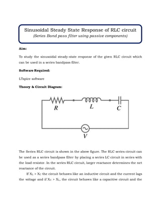
  • 1. Aim: To study the sinusoidal steady-state response of the given RLC circuit which can be used in a series bandpass filter. Software Required: LTspice software Theory & Circuit Diagram: The Series RLC circuit is shown in the above figure. The RLC series circuit can be used as a series bandpass filter by placing a series LC circuit in series with the load resistor. In the series RLC circuit, larger reactance determines the net reactance of the circuit. If XL > XC the circuit behaves like an inductive circuit and the current lags the voltage and if XC > XL, the circuit behaves like a capacitive circuit and the Sinusoidal Steady State Response of RLC circuit (Series Band pass filter using passive components)
  • 2. current leads the voltage. The magnitude and Phase angle of the current, I in the series RLC circuit is obtained using the following equation,   2 2 L C V V I Z R X X       1 tan L C X X R    For RLC circuit with R= 10 Ω, L= 1mH, C= 1 μF and Vm = 100 V, f = 50 Hz, XL = ωL = 2ΠfL = 0.314 Ω, XC = (1/ωC) = (1/ 2ΠfC) = 3184 Ω, Im = 0.0314 A, Φ = 89.82°. In this example, since XC > XL, Current leads the voltage. Procedure: 1. Open LTspice. Go to File New Schematic. 2. On the File Menu, click on Edit Component.
  • 3. 3. Place the voltage sources, resistor, inductor , capacitor and ground on to schematic and make necessary connections as shown in the Figure. 4. As shown in the figures below, Right click on the voltage source V1 and click Advanced option and then Select SINE (Voffset Vamp Freq Td Theta Phi Ncycles) and Set the values as (DC offset = 0, Amplitude =100, Freq = 50).
  • 4. 5. As shown in the figure below, Right click on the resistor, inductor and capacitor and set the value as 10 Ω, 0.001 H and 1 μF respectively
  • 5. 6. Go to Edit → SPICE analysis. Set the type of sweep to Linear, Number of points to 100 and start and stop frequency to 50 each in the AC Analysis command as shown in the figure below and run the simulation. (run symbol on the menu bar). 7. Observe the peak value of the current and phase angle from the obtained output window below and note it in the “Theoretical Value” column of the observation table. 8. For waveforms: Go to Edit → SPICE analysis. Set the stop time to 40ms in Transient command as shown in the figure below and run the simulation. (run symbol on the menu bar).
  • 6. 9. To view the results, right click → Add Trace → Select V (<<input node>>) and I (L1).
  • 7. 10. Observe the waveforms, change the appropriate colors for proper visibility using color preferences and control panel tool. Sample figure shown below.
  • 8. Observation table: S. No. Parameter Theoretical Value Observed Value 1. I (Peak value) 31.41mA 31.417026mA 2. Phase angle 89.82 89.82 Waveforms:
  • 9. Result & Inferences: Thus, a series RLC circuit has been designed and implemented in LTspice software, and the current amplitude and phase angle is observed as 0.0314 A and 89.82° respectively which is matching with Theoretical Values. From the waveforms, it is also observed that the current leads the voltage. Practical Applications: The three circuit elements, R, L, and C can be combined in several different topologies by connecting them in series or parallel. RLC circuits have many applications as follows:  Variable tuned circuit  Filters - Band-pass filter, Band-stop filter, Low-pass filter or High-pass filter  Oscillator  Voltage multiplier  Pulse discharge circuit Course Outcome: CO2. Analyze AC power circuits and networks, its measurement and safety concerns CO6. Design and conduct experiments to analyze and interpret data Student Learning Outcomes (SLO): SLO1. Having an ability to apply mathematics and science in engineering applications SLO9. Having problem-solving ability- solving social issues and engineering problems