
Recommended
More Related Content
What's hot
What's hot (19)
Similar to RLC Parallel Circuit Resonance Simulation
Similar to RLC Parallel Circuit Resonance Simulation (20)
Recently uploaded
Recently uploaded (20)
RLC Parallel Circuit Resonance Simulation
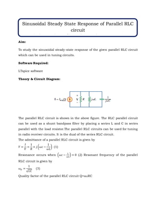
- 1. Aim: To study the sinusoidal steady-state response of the given parallel RLC circuit which can be used in tuning circuits. Software Required: LTspice software Theory & Circuit Diagram: The parallel RLC circuit is shown in the above figure. The RLC parallel circuit can be used as a shunt bandpass filter by placing a series L and C in series parallel with the load resistor.The parallel RLC circuits can be used for tuning in radio receiver circuits. It is the dual of the series RLC circuit. The admittance of a parallel RLC circuit is given by 𝑌 = 𝐼 𝑉 = 1 𝑅 + 𝑗 (𝜔𝑐 − 1 𝜔𝐿 ) (1) Resonance occurs when (𝜔𝑐 − 1 𝜔𝐿 ) = 0 (2) Resonant frequency of the parallel RLC circuit is given by 𝜔𝑂 = 1 √𝐿𝐶 (3) Quality factor of the parallel RLC circuit Q=ω0RC Sinusoidal Steady State Response of Parallel RLC circuit (Series Band pass filter using passive components)
- 2. 𝐵𝑎𝑛𝑑𝑤𝑖𝑑𝑡ℎ = 𝜔0 𝑄 (4) Lower Half power Frequency 𝜔1 = 𝜔0 − 𝐵 2 (5) Upper Half power Frequency 𝜔2 = 𝜔0 − 𝐵 2 (6) A parallel RLC circuit has R=1.5kΩ, L=0.2mH and C=150µF.Determine: (a) the resonant frequency (b) the bandwidth (c) the quality factor Procedure: 1. Open LTspice. Go to File New Schematic. 2. On the File Menu, click on Edit Component.
- 3. 3. Place the voltage sources, resistor, inductor , capacitor and ground on to schematic and make necessary connections as shown in the Figure. Circuit for simulating Parallel RLC circuit: V1 SINE(0 50 100) R1 50 L1 20m C1 5µ ;ac lin 1 100 100 .tran 50m startup
- 4. Results:Plot of Voltage across the circuit and current through the circuit
- 5. Circuit for simulating Parallel RLC resonance: 4. As shown in the figures above, Right click on the AC voltage source V1 and set its magnude as 10V. 5. Go to Edit → SPICE analysis. Set the type of sweep to Decade, Number of points to 101 and start and stop frequency to 10 and 100k respectivelyy each in the AC Analysis command as shown in the figure below and run the simulation. (run symbol on the menu bar). AC 10 V1 R1 1.5k L1 0.2m C1 150µ R2 1 VS .ac dec 101 10 100k
- 6. 6. Observe the supply voltage Vs and and the total current through the circuit.Verify the resonance frequency with the theoretical calculation.
- 8. Observation table: S. No. Parameter Theoretical Value Observed Value 1. Resonant Frequency(ω0) 918.88 918.82 2. Current I through the circuit 10 10 3. Voltage V across the circuit at resonance. 10 10 Result & Inferences: Thus, a parallel RLC circuit has been designed and implemented in LTspice software, and the current amplitude and phase angle is observed as ---- A and --------respectively which is matching with Theoretical Values. From the waveforms, it is also observed that the current leads the voltage. Practical Applications: The three circuit elements, R, L, and C can be combined in several different topologies by connecting them in series or parallel. RLC circuits have many applications as follows: Variable tuned circuit Filters - Band-pass filter, Band-stop filter, Low-pass filter or High-pass filter Course Outcome: CO2. Analyze AC power circuits and networks, its measurement and safety concerns CO6. Design and conduct experiments to analyze and interpret data
- 9. Student Learning Outcomes (SLO): SLO1. Having an ability to apply mathematics and science in engineering applications SLO9. Having problem-solving ability- solving social issues and engineering problems