This document describes simulations of an LCC resonant circuit performed in MATLAB. It includes:
1) Writing an m-file to calculate the input impedance of the LCC circuit with defined component values.
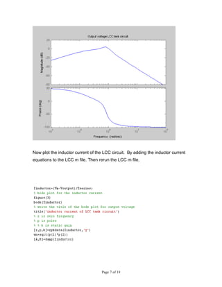
2) Adding equations to plot the output voltage and inductor current by rerunning the m-file.
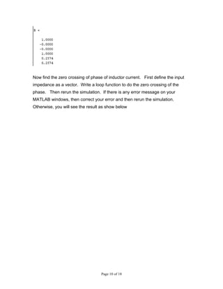
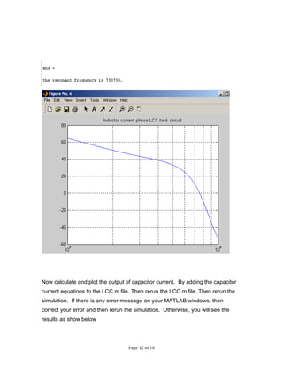
3) Finding the zero crossing of the phase of the inductor current and plotting the capacitor current.
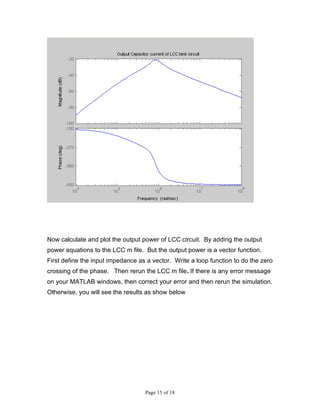
4) Calculating and plotting the output power of the LCC circuit by adding power equations and using a loop function in the m-file.