The document discusses series and parallel resonance circuits. Some key points:
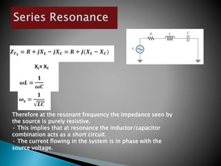
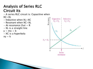
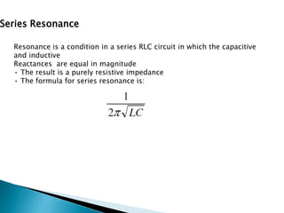
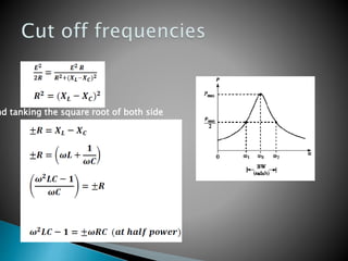
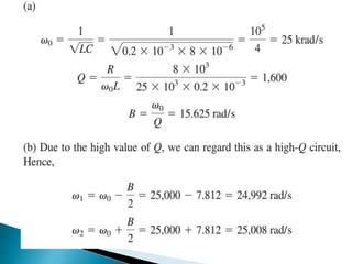
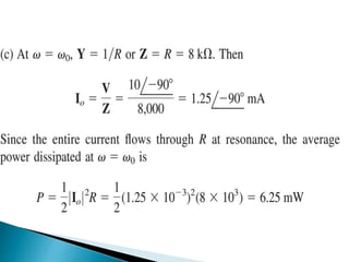
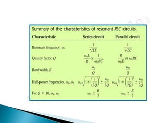
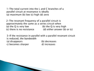
- In a series RLC circuit, the impedance is purely resistive at resonance when the inductive and capacitive reactances are equal. Maximum current flows at this resonant frequency.
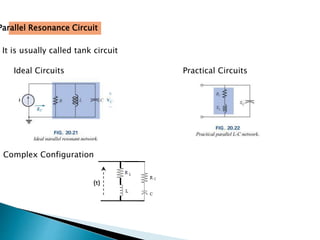
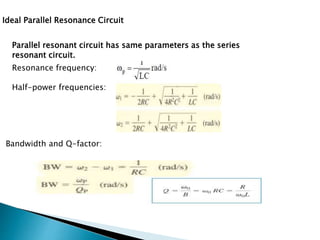
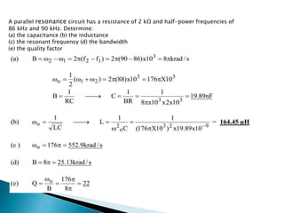
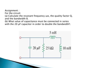
- Parallel RLC circuits also exhibit resonance when the reactances cancel out. Minimum current flows at resonance for a parallel circuit.
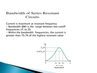
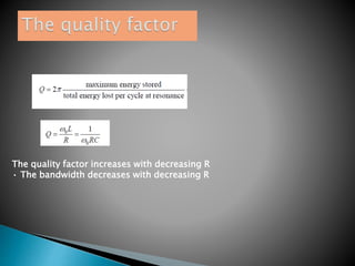
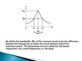
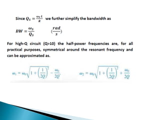
- For both circuits, the quality factor Q and bandwidth depend on the resistance, with lower resistance leading to higher Q and narrower bandwidth.