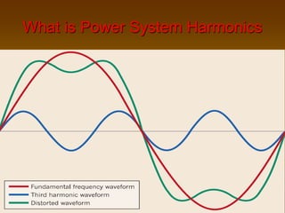
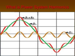
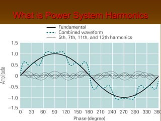
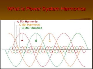
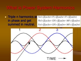
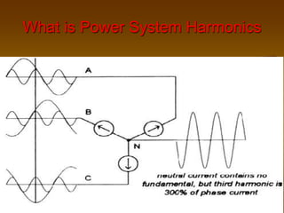
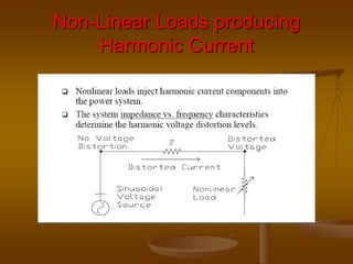
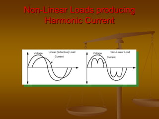
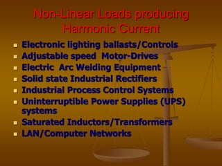
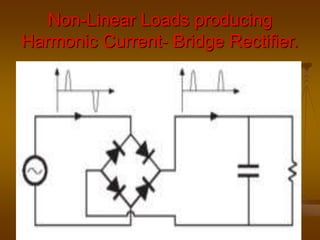
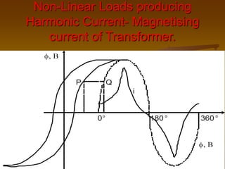
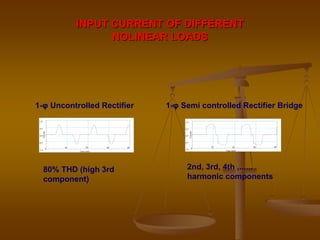
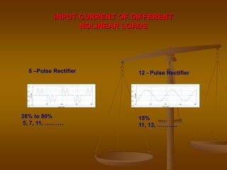
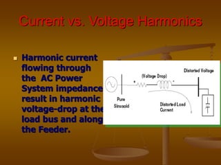
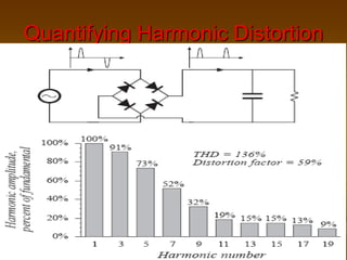
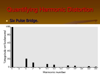
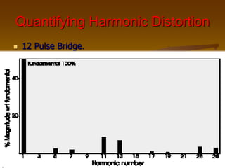
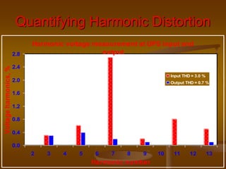
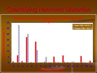
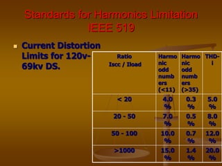
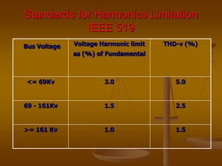
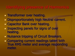
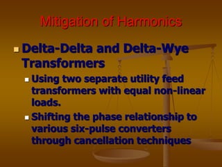
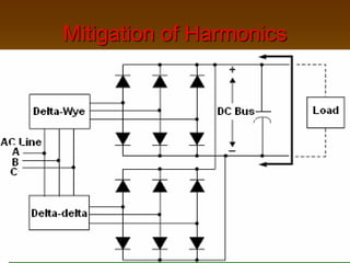
3. Topics of Discussion
What is Power System Harmonics
Nonlinear Loads Producing Harmonic
Currents
Harmonic Distortion
Identifying presence of Harmonics
Negative Effects of Harmonics
Harmonic Control
Positive uses of Harmonics
Conclusions
4. What is Power System
Harmonics
Power system harmonics: currents or
voltages with frequencies that are
integer multiples (h=0,1,2,…N) of
the fundamental power frequency
1st harmonic: 50Hz
2nd harmonic: 100Hz
3rd harmonic: 150Hz and so on….
5. What is Power System Harmonics
Power system harmonics: presenting
deviations from a perfect sinusoidal-
waveform (voltage or current
waveform).
The distortion comes from a
Nonlinearity caused by saturation,
arcing electronic-switching and
nonlinear electric loads.
6. What is Power System Harmonics
Any non-sinusoidal periodic wave form can
be split to a no: of sinusoidal waves of
different harmonic frequencies by Fourier
Theorem.
In converse, when ever there is harmonics
present in the system the wave form gets
distorted and becomes complex or non-
sinusoidal.
10. What is Power System Harmonics
For balanced 3 phase systems, the characteristic
harmonics are all odd.
When ever there is even harmonics, the positive
and negative half cycle of the complex wave will
be unsymmetrical.
When the harmonics are all odd, the positive
and negative half cycle of the complex wave are
symmetrical.
A P-Pulse converter produces harmonics of order
given by h= nP+-1 in the AC side, where n=
1,2,…., etc.
11. What is Power System Harmonics
)
t
sin(
2 h
1
h
h
Ih
General expression for a complex function I (t)
12. What is Power System Harmonics
RMS value of a
complex current (or
voltage) wave is the
square root of the
sum of the squares of
its individual
components.
2
max
2
max
2
max
2
max
2
...
2
2
2
3
2
1
m
I
I
I
I
I
15. What is Power System Harmonics
Harmonic sequence is the phase rotation relationship with respect to
the fundamental component.
Positive sequence harmonics ( 4th, 7th, 10th , ……. (6n+1) th )
have the same phase rotation as the fundamental component.
These harmonics circulate between the phases.
Negative sequence harmonics ( 2nd, 5th, 8th ……… (6n-1) th )
have the opposite phase rotation with respect to the fundamental
component. These harmonics circulate between the phases.
Zero sequence harmonics ( 3rd, 6th, 9th, ….. (6n-3) th ) do not
produce a rotating field. These harmonics circulate between the
phase and neutral or ground. These third order or zero sequence
harmonics, unlike positive and negative sequence harmonic
currents, do not cancel but add up arithmetically at the neutral bus.
24. INPUT CURRENT OF DIFFERENT
NOLINEAR LOADS
0
10 20 30 40
-1.0
-0.5
0.0
0.5
1.0
Time (mS)
Current
80% THD (high 3rd
component)
1-φ Uncontrolled Rectifier
0
10 20 30 40
-1.0
-0.5
0.0
0.5
1.0
Time (mS)
Current
1-φ Semi controlled Rectifier Bridge
2nd, 3rd, 4th ,......
harmonic components
25. INPUT CURRENT OF DIFFERENT
NOLINEAR LOADS
0
10 20 30 40
-1.0
-0.5
0.0
0.5
1.0
Time (mS)
Current
6 –Pulse Rectifier
28% to 80%
5, 7, 11, ……….
0 10 20 30 40
-1.0
-0.5
0.0
0.5
1.0
Time (mS)
Current
12 - Pulse Rectifier
15%
11, 13, ………..
26. Current vs. Voltage Harmonics
Harmonic current
flowing through
the AC Power
System impedance
result in harmonic
voltage-drop at the
load bus and along
the Feeder.
27. Quantifying Harmonic Distortion
Total Harmonic Distortion-THD: the
contribution of all harmonic
frequency Currents/Voltages to the
fundamental current.
Individual Distortion Factor-(DF)-h
quantify Distortion at h –harmonic-
order
30. Quantifying Harmonic Distortion
The Individual
Harmonic Distortion
( IHD ) at a particular
harmonic frequency is
the root mean square
( rms ) of the
harmonic under
consideration to the
rms value of the
fundamental.
%
100
1
I
I
IHD h
Ih
31. Current vs. Voltage Harmonics
Harmonic current flowing through
the AC Power System impedance
result in harmonic voltage-drop at
the load bus and along the Feeder.
Lesser the System impedance, lower
will be the voltage distortion.
37. Standards for Harmonics Limitation
IEEE 519
Current Distortion
Limits for 120v-
69kv DS.
Ratio
Iscc / Iload
Harmo
nic
odd
numb
ers
(<11)
Harmo
nic
odd
numb
ers
(>35)
THD-
i
< 20 4.0
%
0.3
%
5.0
%
20 - 50 7.0
%
0.5
%
8.0
%
50 - 100 10.0
%
0.7
%
12.0
%
>1000 15.0
%
1.4
%
20.0
%
38. Standards for Harmonics Limitation
IEEE 519
Bus Voltage Voltage Harmonic limit
as (%) of Fundamental
THD-v (%)
<= 69Kv 3.0 5.0
69 - 161Kv 1.5 2.5
>= 161 Kv 1.0 1.5
39. Identifying presence of Harmonics
Transformer over heating.
Disproportionately high Neutral current.
Capacitor Bank over heating.
Inspecting panels for signs of over
heating.
Nuisance tripping of Circuit Breakers.
Comparing current readings taken with
True RMS meter and average responding
meter.
40. Identifying presence of Harmonics
Digital Oscilloscope:
Wave shape, THD and Amplitude of
each harmonic.
Use of Harmonic Meters-Single Phase or
three Phase.
41. Negative Effects of Harmonics
Resistive loads - will absorb slightly more
power
Motor loads - harmonic fluxes within the
motor
Power transformers - hot spots within the
windings
Electronic controls - operate improperly
Communication circuits - can cause
interference
42. Negative Effects of Harmonics
Voltage Harmonics can cause additional
heating in induction and synchronous
motors and generators.
Voltage Harmonics with high peak values
can weaken insulation in cables, windings,
and capacitors.
Voltage Harmonics can cause malfunction
of different electronic components and
circuits that utilize the voltage waveform
for synchronization or timing.
43. Negative Effects of Harmonics
Current Harmonics flowing through cables
can cause higher heating over and above
the heating that is created from the
fundamental component.
Current Harmonics flowing through a
transformer can cause higher heating over
and above the heating that is created by
the fundamental component.
Current Harmonics flowing through circuit
breakers and switch-gear can increase
their heating losses.
44. Negative Effects of Harmonics
In general, harmonics increase heating
and losses in almost every piece of
equipment in the electric power system.
High TRV in Circuit Breakers.
Reduced Power Factor.
Over heating of phase conductors due to
skin effect.
Digital Clocks advance in time due to
additional zero crossings.
45. Negative Effects of Harmonics
Overheating and premature failure of distribution
transformers
Increasing iron and copper losses or eddy currents due
to stray flux losses.
Overheating and mechanical oscillations in the
motor-load system
Producing rotating magnitude field, which is opposite to
the fundamental magnitude field.
Overheating and damage of neutral ground
conductors
A 3-phase 4-wire system: Triple n harmonics will add
rather than cancel on the neutral conductor.
46. Negative Effects of Harmonics
False or spurious Relay operations and trips of
Circuit Breakers.
Failure of the Firing/Commutation circuits, found
in DC motor-drives and AC drives with Silicon
Controlled Rectifiers.
Mal-Operation instability of voltage regulator.
Power factor correction capacitor failure
Reactance (impedance)-Zc of a capacitor bank decreases
as the frequency increases.
Capacitor bank acts as a sink for higher harmonic
currents.
The System-Series and parallel Resonance can cause
dielectric failure or rupture the power factor correction
capacitor failure due to Over-Voltages & Over-Currents.
47. Negative Effects of Harmonics-
Parallel Resonance
Harmonic currents produced by variable speed
motor-drives: can be amplified up to 10-15 times
in parallel resonance circuit formed by the
capacitance bank and network inductance
Amplified/intensified harmonic currents:
leading to internal overheating of the capacitor
unit.
Higher frequency currents: causing more losses
than 50hz currents having same amplitude.
49. Negative Effects of Harmonics-
Series Resonance
The voltage of upstream AC Network
can be also distorted due to series
resonance formed by capacitance of
the capacitor bank and System/load
inductance : Can cause high
harmonic current circulation through
the capacitors.
51. Mitigation of Harmonics
Power System Design:
Limiting non-linear loads to
15% of the transformer’s
capacity, when power factor
correction capacitors are
installed.
Avoiding/Detuning resonant
conditions on the AC System:
52. Mitigation of Harmonics
Delta-Delta and Delta-Wye
Transformers
Using two separate utility feed
transformers with equal non-linear
loads.
Shifting the phase relationship to
various six-pulse converters
through cancellation techniques
54. Mitigation of Harmonics
Line Isolation-Reactors
More commonly used for their low cost
Adding a small reactor in series with
capacitor bank forms a Blocking series
Filter.
55. Mitigation of Harmonics
Harmonic-Shunt or Trap Filters:
Used in applications with a high non-
linear ratio to system to eliminate
harmonic currents
Sized to withstand the RMS current as
well as the value of current for the
harmonics
Providing true distortion power factor
correction
57. Mitigation of Harmonics
Tuned to a specific harmonic order
such as the 5th, 7th, 11th,… etc to
meet requirements of IEEE 519-1992
Standard
The number of tuned filter-branches
depends on the offending steady-
state harmonics to be absorbed and
on required reactive power level to
be compensated
59. Mitigation of Harmonics
Isolating harmonic current to protect electrical
equipment from damage due to harmonic voltage
distortion
Passive Filter-Low cost:
Built-up by combinations of capacitors, inductors
(reactors) and resistors
most common and available for all voltage levels
Active Power Filter APF:
Inserting negative phase compensating harmonics into
the AC-Network, thus eliminating the undesirable
harmonics on the AC Power Network.
APF-Used only for for low voltage networks
60. Positive uses of Harmonics
Second Harmonic current used to provide
restraint against mal operation of Transformer
Differential Relay during charging.
Fifth Harmonic current used to provide restraint
against mal operation of Transformer Differential
Relay during over excitation conditions.
Third Harmonic voltage based techniques used
to provide 100% Stator Earth Fault protection
for high impedance grounded Generators.
61. Conclusion
The harmonic distortion principally comes
from Nonlinear-Type Loads.
The application of power electronics is
causing increased level of harmonics due
to Switching.
Harmonic distortion can cause serious
Failure/Damage problems.
Harmonics are important aspect of power
operation that requires Mitigation.
Over-Sizing and Power Filtering methods
are commonly used to limit Overheating
Effects of Sustained Harmonics.
62. References
IEEE 519 “Recommended Practices and
Requirements for Harmonic Control in
Electric Power Systems.
Electrical Technology- Vol.2 by A.K.
Thereja & B.L. Thereja.
www.schneiderelectric.com