The document provides information on various arithmetic and logical instructions used in x86 assembly language. It describes instructions for addition, subtraction, comparison, negation and more. It also covers logical instructions for AND, OR, XOR, NOT, shift and rotate operations. Examples are given to demonstrate how instructions work and how they affect registers and flags.


![• Operation Performed :--
• Destination Destination AND source
• Examples :--
1. AND BH,CL ;AND byte in CL with Byte in BH,
result in BH.
2. AND BX,00FFH ;AND word in BX with immediate
data 00ffH
3. AND [5000H], DX ;AND word in DX with a
word in memory with offset
5000 in DS.
AND (Logical AND) contd..](https://image.slidesharecdn.com/chap38086logical-200319141118/75/Chap3-8086-logical-5-2048.jpg)

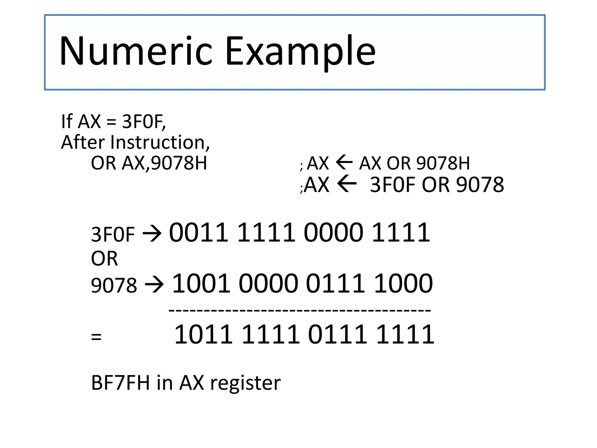
![• Operation Performed :--
• Destination Destination OR source
• Examples :--
1. OR BH,CL ;OR byte in CL with Byte in BH,
result in BH.
2. OR BX,00FFH ;OR word in BX with immediate
data 00ffH
3. OR [5000H], DX ; OR word in DX with a
word in memory with offset
5000 in DS.
OR (Logical OR) contd..](https://image.slidesharecdn.com/chap38086logical-200319141118/75/Chap3-8086-logical-8-2048.jpg)
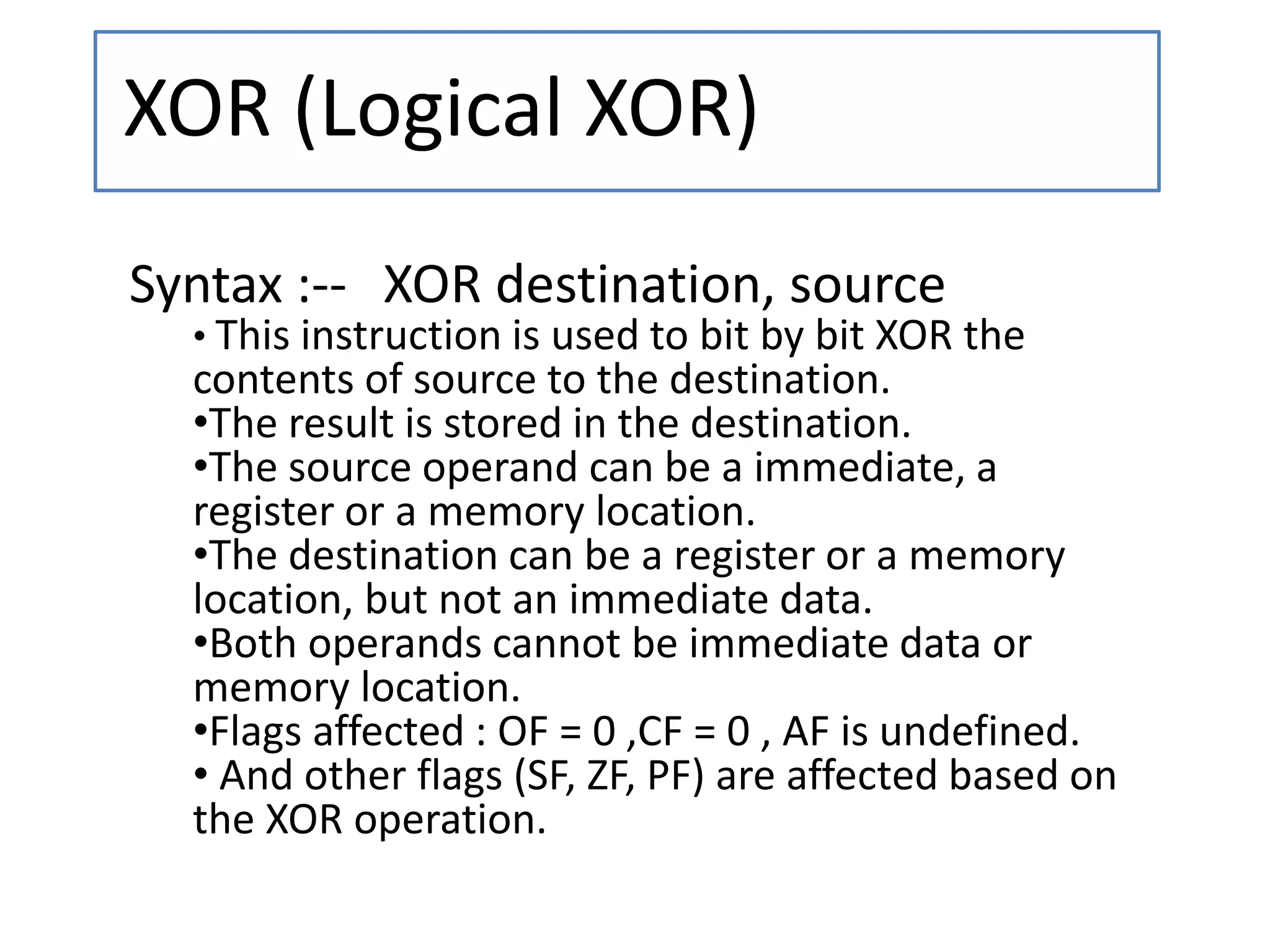
![• Operation Performed :--
• Destination Destination XOR source
• Examples :--
1. XOR BH,CL ;XOR byte in CL with Byte in BH,
result in BH.
2. XOR BX,00FFH ;XOR word in BX with immediate
data 00ffH
3. XOR [5000H], DX ; XOR word in DX with a
word in memory with offset
5000 in DS.
XOR (Logical XOR) contd..](https://image.slidesharecdn.com/chap38086logical-200319141118/75/Chap3-8086-logical-11-2048.jpg)


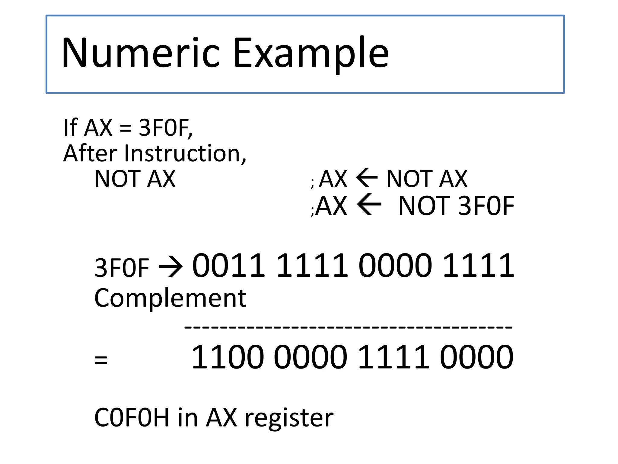
![• Operation Performed :--
• Destination NOT Destination
• Examples :--
1. NOT BH ;Complement byte in BH, result in BH.
2. NOT BX ; Complement word in BX, result in BX.
3. NOT BYTE PTR [5000H] ; Complement byte
in memory with offset 5000 in DS.
NOT (Logical Invert ) contd..](https://image.slidesharecdn.com/chap38086logical-200319141118/75/Chap3-8086-logical-14-2048.jpg)

![• Operation Performed :--
– Flags set result of Destination AND source
• Examples :--
1. TEST BH,CL ;AND byte in CL with Byte in BH,
no result but flags are affected.
2. TEST BX,00FFH ;AND word in BX with immediate
data 00ffH, no result but flags are
affected.
3. TEST DX, [5000H];AND word in DX with a word in
memory with offset 5000 in DS,
no result but flags are affected.
TEST (Logical Compare) contd..](https://image.slidesharecdn.com/chap38086logical-200319141118/75/Chap3-8086-logical-17-2048.jpg)
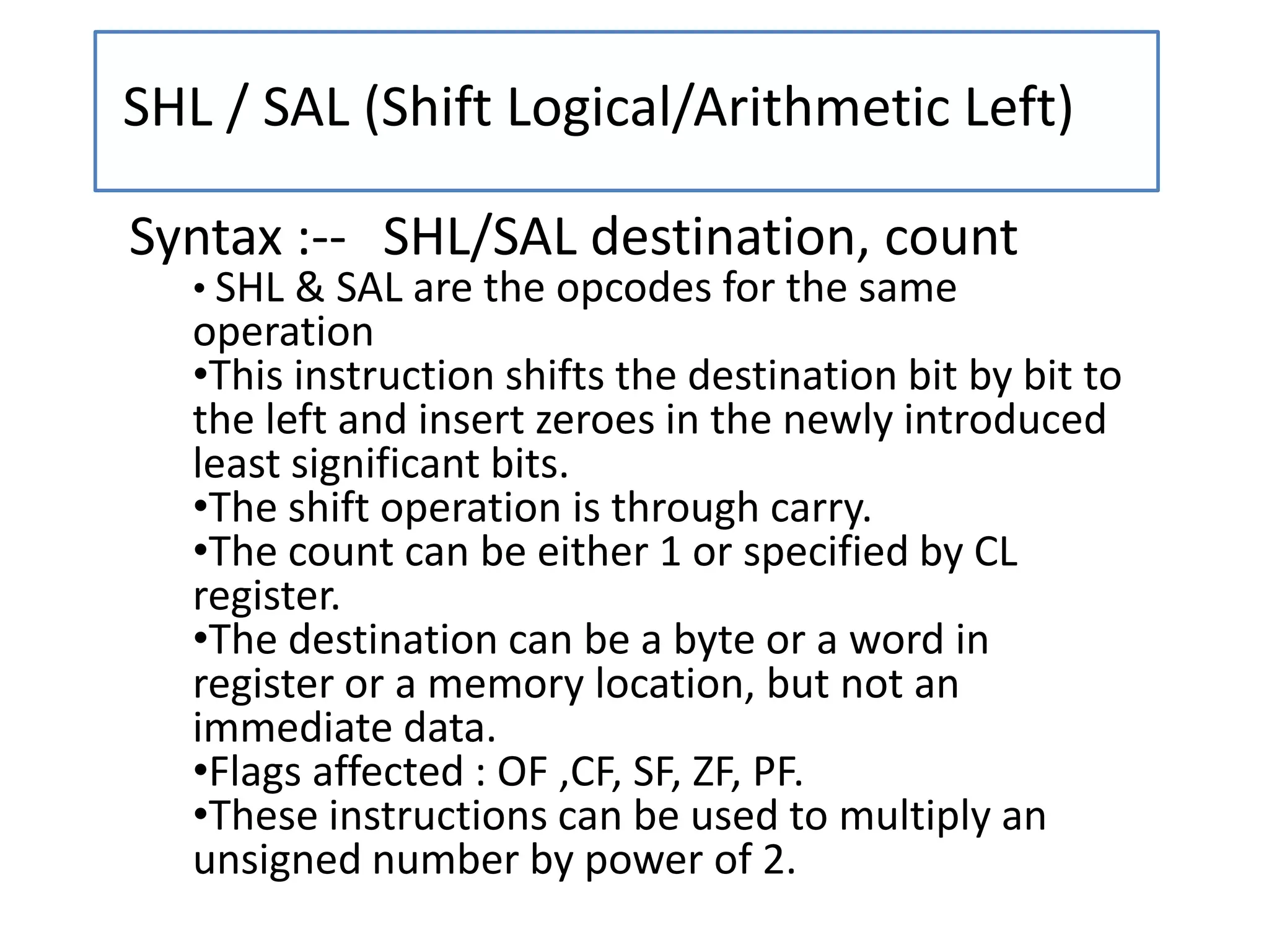

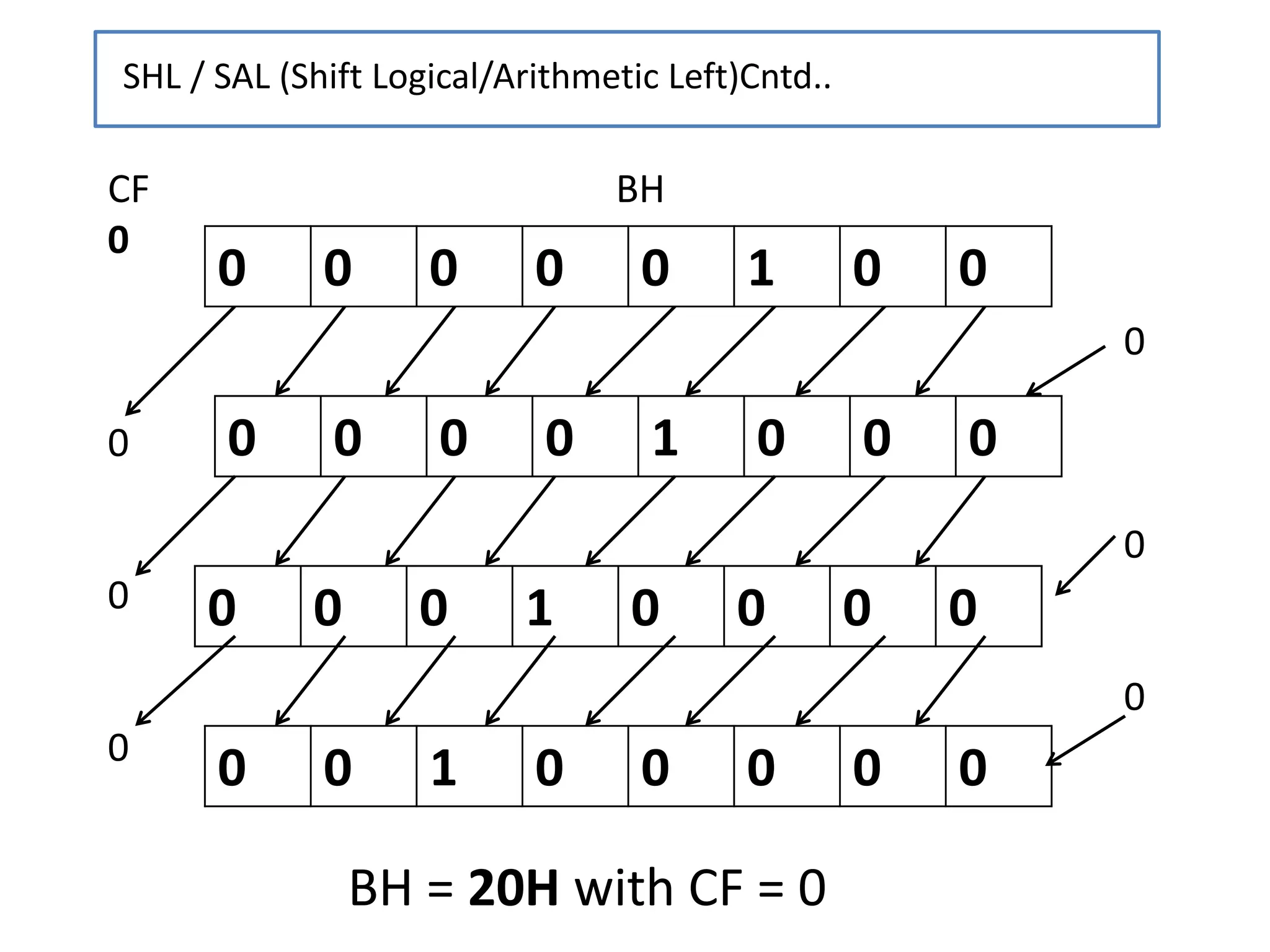
![• Example :--
• Use of SHL instruction for Multiplication:-
– If CF = 0, BH = 04H
– MOV CL, 03 ; Load CL register for
the count
– SHL BH, CL ; Shift the contents
of BX register by one
towards left
– BH = 20H (32D) [ 04 * 23 = 32 D]
– Note :-- SHL can be used to multiply a number
with powers of 2.
SHL / SAL (Shift Logical/Arithmetic Left)Cntd..](https://image.slidesharecdn.com/chap38086logical-200319141118/75/Chap3-8086-logical-20-2048.jpg)
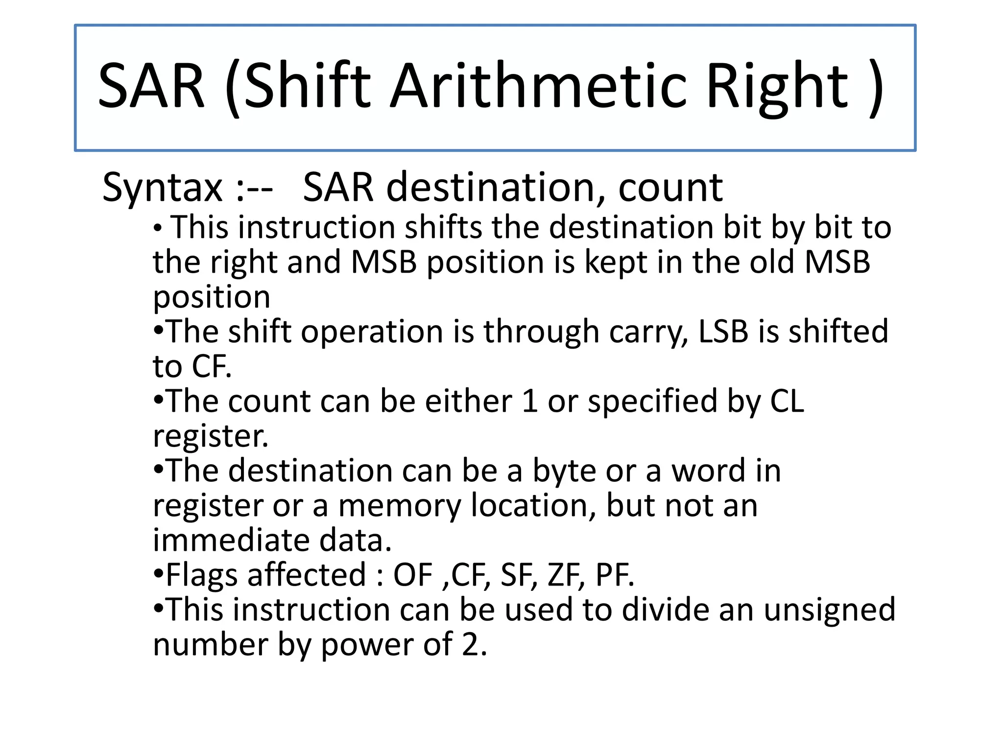

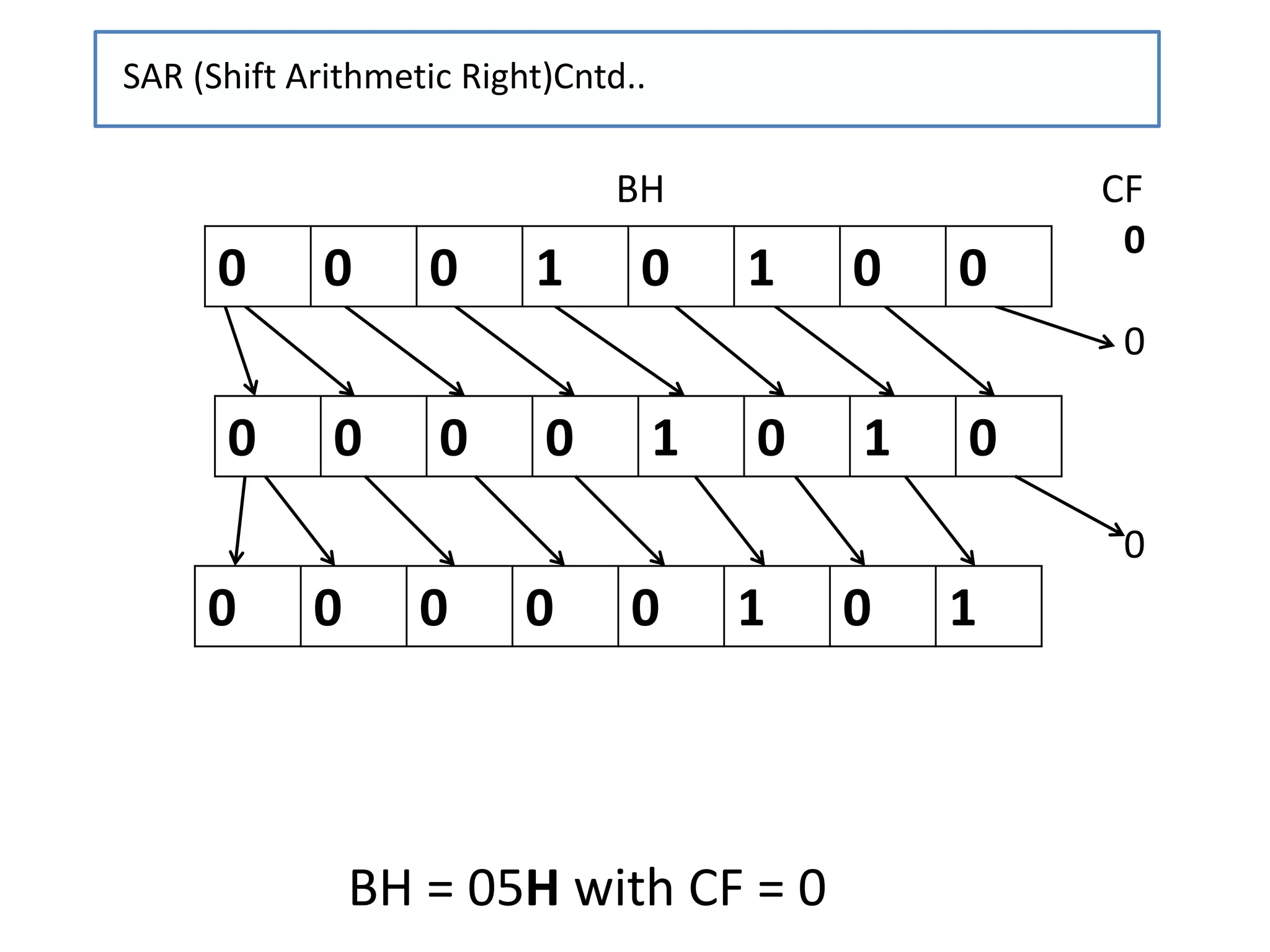
![• Example :--
• Use of SAR instruction for Division:-
– If CF = 0, BH = 14H
– MOV CL, 02 ; Load CL register for the
count
– SAR BH, CL ; Shift the contents
of BX register by one
towards right
– BH = 05H (20D) [ 20 / 22 = 05D]
– Note :-- SAR can be used to divide a number with
powers of 2 and get the quotient.
SAR (Shift Arithmetic Right )Cntd..](https://image.slidesharecdn.com/chap38086logical-200319141118/75/Chap3-8086-logical-24-2048.jpg)


![[ASM]Lab7](https://cdn.slidesharecdn.com/ss_thumbnails/asmlab7-151121102306-lva1-app6891-thumbnail.jpg?width=640&height=640&fit=bounds)