Download to read offline
![IJRET: International Journal of Research in Engineering and Technology eISSN: 2319-1163 | pISSN: 2321-7308
_______________________________________________________________________________________
Volume: 03 Issue: 01 | Jan-2014, Available @ http://www.ijret.org 217
LV SIDE DISTRIBUTED POWER FACTOR CORRECTION SYSTEM Santosh K. Verma1, Akash Sunil Gaikwad2 1M.Tech, Electrical Engineering, NIT Agartala, Tripura, India 2B.Tech, Electronics & Communication Engineering, NIT Agartala, Tripura, India Abstract Power factor is a very important parameter of power system. In an electric power system, a load with a low power factor draws more current than a load with a high power factor for the same amount of useful power transferred. The higher currents increase the energy lost in the distribution system, and require larger wires and other equipment leading to increase in the cost of the system [1]. So it is very necessary to have a good power factor. Here we have proposed a Low Voltage (LV) side distributed model to correct the power factor of the power system. It can reduce the losses in the transmission, system size, cost of the system and complexity in the instalment. We have also designed a low cost, reliable, efficient system using ATmega16 (8-bit CPU) from Atmel Corporation which can be used in the proposed system for automatic correction of the power factor. Keywords: Power Factor, Automatic Power factor Correction System, AVR, ATmega16, Capacitor Bank, Power System etc…
--------------------------------------------------------------------***---------------------------------------------------------------------- 1. INTRODUCTION In electrical engineering, the power factor of an AC electrical power system is defined as the ratio of the real power flowing to the load, to the apparent power in the circuit [2], and is a dimensionless number between -1 and 1[3]. If we denote real power with P and apparent power with S then: Power Factor = P/S (1) If we denote power factor by Cos (ⱷ), where ⱷ is the angle between the real power and apparent power or phase difference between current and voltage; then real power flowing in the system will be: P=VI Cos (ⱷ) (2) At ⱷ=0°, Cos (ⱷ) =1, putting these values in equation (2): P=VI*1 PMAX=VI (3) So for the maximum value of real power to be transferred power factor should be equal to one in other words the current and voltage should be in the same phase. In the power system power factor is generally kept between 0.9 and 0.95[4]. 2. PROPOSED MODEL
We are using power correction devices generally at substations marked with “A” in the figure below. A part of power is wasted in the transmission lines before it reaches to the user. There are several more problems occur in case of system we use now days i.e. instalment cost, maintenance, re instalment on system failure. So here we have proposed a distributed system of power factor correction system at LV side which will inject the reactive power at the user level instead of substations to do so we can install a small device for every user which will fulfil the need of reactive power for that particular user. This proposed model has several advantages over what we are using now days as explained below. A block diagram of proposed model is shown below:
Fig-1: Block Diagram Advantages of Proposed Model:
1. In case of our proposed model the system is distributed over user level so in case, if any unit fails we will still have the other unit to compensate the effect.
2. In case of system failure re instalment of device will not be expensive.
3. It will reduce the complexity in instalment.](https://image.slidesharecdn.com/lvsidedistributedpowerfactorcorrectionsystem-141117110728-conversion-gate02/75/Lv-side-distributed-power-factor-correction-system-1-2048.jpg)
![IJRET: International Journal of Research in Engineering and Technology eISSN: 2319-1163 | pISSN: 2321-7308
_______________________________________________________________________________________
Volume: 03 Issue: 01 | Jan-2014, Available @ http://www.ijret.org 218
4. Voltage at distribution side is quite low (220/440 V) and designing and manufacturing of capacitor used in capacitor bank for power factor correction is easy and economical as compared to high voltage capacitors. This will reduce the cost of the system.
5. If we inject the reactive power at user level then we can save a part of electrical energy which being wasted in the transmission. This will improve the efficiency of the system.
6. We can improve the system response by using our proposed model as we know that a small unit can response faster than a big one.
7. We can design system with higher precision and repeatability.
These are few advantage of using our proposed model but still there are many more to discover 3. SYSTEM DESIGN OF AUTOMATED POWER FACTOR CORRECTION SYSTEM For the system design of automated power factor correction system we have used ATmega16 (8 bit CPU) from Atmel Corporation as processing and calculating device. It comes in 40 pin DIP package having 32 I/O pins, one 16 bit timer/counter named as timer1, one 10 bit ADC using successive approximation technique for Analog to digital conversion, capable of taking 16 K samples per second and Interrupt pins capable of triggering software interrupts on external events i.e. rising edge, falling edge or on logic change [5]. For the measurement of load current we have used ACS712ELCTR-20A-T Current sensor module capable of measuring A.C. current up to 20 A. Its output is calibrated to give 100mV per Ampere of input current [6]. Block diagram of the whole system is shown below:
Fig-2: System Design
As for the power factor control we need both phase angle and the load current. So we can explain the whole system design in following steps:
3.1. Measurement of Phase Angle:
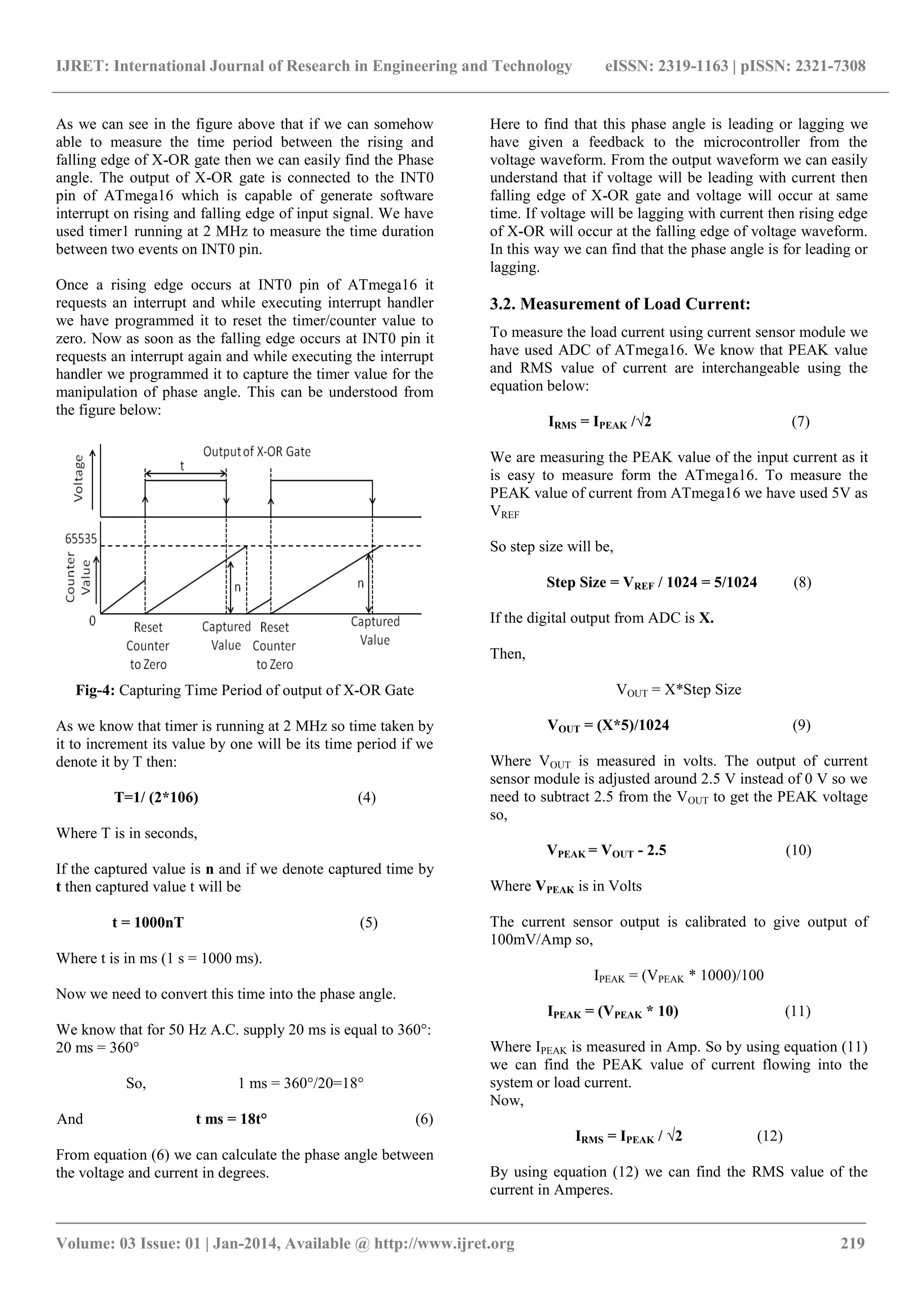
Here our task is to measure the Phase angle between the voltage and current. There are many techniques to measure the phase difference but voltage and current but as using microcontroller we can measure the time period very easily and accurately so here we are using the time measurement technique to measure the phase angle. We are measuring the time delay between the voltage and current and then we are converting it back in the angle. To measure the time delay between the voltage and current first of all we have passed the voltage waveform to the zero crossing detector circuit (ZCD) through a step down transformer to convert it in digital format. Again we have passed the output of the current sensor module to the zero crossing detector circuit (ZCD) to get the current waveform in the digital format (reference voltage in case of current waveform to ZCD is 2.5 V instead of 0 V because output of current sensor is adjusted about 2.5 V not 0 V. Here current sensor module output varies with the input current passing through it so it works as I-V converter. We are also using it for the measurement of load current) both current and voltage waveform from both zero crossing detector circuit (ZCD) circuit is passed to an X-OR gate. We are getting high level voltage at its output only during the time which is equal to the lag or lead time. It can be understand easily from the figure below:
Fig-3: Output Wave forms](https://image.slidesharecdn.com/lvsidedistributedpowerfactorcorrectionsystem-141117110728-conversion-gate02/75/Lv-side-distributed-power-factor-correction-system-2-2048.jpg)
![IJRET: International Journal of Research in Engineering and Technology eISSN: 2319-1163 | pISSN: 2321-7308
_______________________________________________________________________________________
Volume: 03 Issue: 01 | Jan-2014, Available @ http://www.ijret.org 221
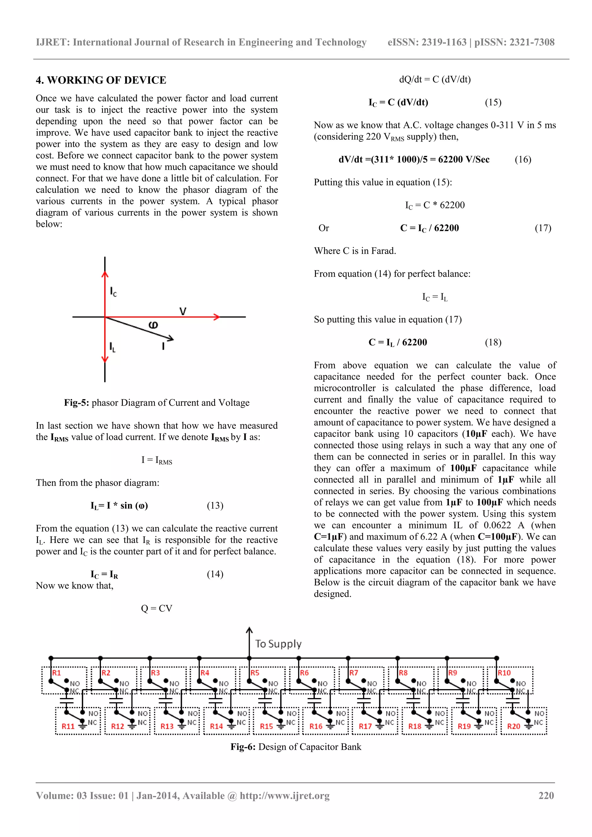
We have not shown here the energy coil of the relays for the simplicity. They should be considered connected properly. As we can see here that initially all capacitors are connected in parallel offering a total capacitance of 100μF. Algorithm to find the number of capacitors required to connect in series or parallel for a particular value of capacitance: once we have capacitance value then we need to know that in above design of capacitor bank out of 10 how many capacitors we required to connect in series and how many are required to connect in parallel.
In the value of capacitance value the number at tenth place is directly equal to capacitor required to connect in parallel i.e. for C = 25, Two will be the required no. of capacitors to connect in parallel. So, Parallel capacitors = no. at tenth place (19) And by taking the inverse of No. at unit place multiplied by 0.1will give us the capacitors required to connect in series i.e. for C=25, it will be 1/(5*0.1) = 2. So, Series capacitor= 1/ (0.1 * no. at unit place) (20) Here in case of float value chose nearest integer greater than float value. By using equation (19) and equation (20) we can find the no. of capacitance required to connect in series and parallel from the value of capacitance. 5. CONCLUSIONS In this paper, we have proposed a distributed model of power factor correction system and their advantages over what is being used now days. We have also suggested a process of manufacturing of a very low cost, reliable and easy to install automated power factor correction system using ATmega16, 8 bit microcontroller from Atmel Corporation. REFERENCES
[1] C.A Heger, P. K. Sen, A Morroni, “Power factor correction — A fresh look into today's electrical systems,” Cement Industry Technical Conference, 2012 IEEE-IAS/PCA 53rd, pp.1-13,May.2012.
[2] Prasad Phad, Pranav Ukkadgaonkar, Sagar Jundare, Abhijeet Borse, “Minimizing the Penalty in Industrial Sector by Engaging the Automatic Power Factor Correction Panel using Microcontroller,” Multidisciplinary Journal of Research in Engineering and Technology, Volume 1, Issue 1 (April 2014) Pg.73-79.
[3] Source Wikipedia.Availiable: http://en.wikipedia.org/wiki/Power_factor
[4] Source Wikipedia.Availiable: http://en.wikipedia.org/wiki/Power_factor
[5] “ATmega16(L) Datasheet,”. [Online]. Available: http://www.atmel.com/Images/doc2466.pdf
[6] “ACS712 Datasheet,”. [Online]. Available: http://www.mpja.com/download/ACS712.pdf
BIOGRAPHIES
Santosh K. Verma, currently in First year Pursuing (M.Tech) Master of Technology (Electrical Engineering) from “National Institute of Technology, Agartala
Email- santoshverma2692@gmail.com Phone No- +91 98 62 39 88 92
Akash Sunil Gaikwad, currently in final year Pursuing (B.Tech) Bachelor of Technology (Electronics & Communication Engineering) from “National Institute of Technology, Agartala.
Email- akashragi@gmail.com Phone No- +91 98 62 10 24 86](https://image.slidesharecdn.com/lvsidedistributedpowerfactorcorrectionsystem-141117110728-conversion-gate02/75/Lv-side-distributed-power-factor-correction-system-5-2048.jpg)

This document describes a proposed distributed power factor correction system and an automated power factor correction system design using a microcontroller. The proposed distributed system would install small power factor correction devices at the user level rather than just at substations. This would inject reactive power closer to the load to improve efficiency. The design uses an ATmega16 microcontroller to measure the phase angle between voltage and current using a zero crossing detector. It also measures the load current using an current sensor and ADC. Based on these measurements, it calculates the required capacitance and controls a capacitor bank to improve the power factor.