This paper discusses a method for minimizing the total harmonic distortion (THD) in the output voltage of a 9-level asymmetric single-phase cascaded multilevel inverter using a genetic algorithm to optimize switching angles. The proposed method reduces THD effectively without changing the conventional switching algorithm, making it applicable to various types of multilevel inverters. Simulation results demonstrate the effectiveness and accuracy of this optimization approach, confirming its potential for enhancing output power quality in inverters.
![The International Journal Of Engineering And Science (IJES)
|| Volume || 4 || Issue || 2 || Pages || PP.40-44|| 2015 ||
ISSN (e): 2319 – 1813 ISSN (p): 2319 – 1805
www.theijes.com The IJES Page 40
THD Minimisation for Phase Voltage of Multilevel Inverters
Using Genetic Algorithm
Shahab Yousefizad, 2
Vahab Yousefizad, 3
Vahid Eslampanah ,
4
Hamid Abbasi
1
Student, Department of Electrical Engineering, Tafresh University, Tafresh, Iran
2
Student, Department of Electrical Engineering, Sahand University of Technology, Tabriz, Iran
3
Student, Department of Electrical Engineering, Sahand University of Technology, Tabriz, Iran
4
Student, Department of Electrical Engineering, Tafresh University, Tafresh, Iran
--------------------------------------------------------ABSTRACT-----------------------------------------------------------
Researchers try to enhance the efficiency and quality of the output power of multilevel inverters. But it should
be noted that, it is not easy to change the inverter switching algorithm and doing this will increases the costs.
Also these algorithms are not usually extensible to all inverter types. By considering these limitations, in this
paper the THD equation of the output voltage of an asymmetric single phase cascaded multilevel inverter
capable of generating 9 output voltage levels is extracted. This equation will be a function of switching angles
and input voltage source values. Now, with the use of genetic algorithm which is one of the strongest
optimization tools, the voltage THD is minimized and the optimized switching angles are obtained. By applying
these angles in the conventional switching algorithm with fundamental frequency, the quality of the output
voltage reaches its highest level. The method used in this paper is simpler than the switching algorithm
changing method and can be generalized to different types of multilevel inverters. Also the use of fundamental
switching frequency, will reduce switching losses. The simulation results obtained by MATLAB/SIMULINK
software, confirm the performance accuracy of the proposed method.
KEYWORDS - Asymmetric cascaded inverter, Genetic algorithm, Multilevel inverter, Optimization, THD.
-------------------------------------------------------------------------------------------------------------------------------------
Date of Submission: 03-February 2015, Date of Accepted : 20-February 2015
-------------------------------------------------------------------------------------------------------------------------------------
I. INTRODUCTION
Today inverters are widely used in industry. For example motor drives, energy storage systems, energy
production with the use of renewable energy sources and etc [1]. Therefore inverters are highly valued and
researchers try to improve their output power quality. With the increase of the number of levels in the inverters
output, output voltage total harmonic distortion (THD) is reduced [2]. Also the value of is reduced [3]
and this improves voltage quality. Because of this and the existence of limitations in the application of two-level
inverters [4], it is recommended to use multilevel inverters in medium voltage and high power applications such
as active power filters, static compensators and etc. The use of multilevel inverters also reduces switching losses
[5]. These inverters are mainly divided into three types of diode clamped, flying capacitor and cascade [6].
Figure (1) shows the basic structures of these inverters [7].
1.1 Diode clamped inverter
This inverter proposed by "Nabae" in 1981 [8] and actually it was a three-level inverter. The key
components of this inverter are clamped diodes. For a single phase m-level diode clamped inverter, Equation (1)
shows the number of DC-link capacitors (Nc). Equation (2) shows the number of switching components (Nd) and
Equation (3) shows the number of clamped diodes (Ncd).
Nc = m-1 (1)
Nd = 2(m-1) (2)
Ncd = 2(m-2) (3)](https://image.slidesharecdn.com/g042040045-150310022913-conversion-gate01/85/THD-Minimisation-for-Phase-Voltage-of-Multilevel-Inverters-Using-Genetic-Algorithm-1-320.jpg)
![ THD Minimisation for Phase Voltage of…
www.theijes.com The IJES Page 41
Figure 1. Multilevel inverters. (a) Diode clamped. (b) Flying capacitor. (c) Cascade.
Diode clamped inverter is efficient in fundamental switching frequency. But using this frequency results in high
output voltage and current THD and these reduce the delivery power quality. In other side, increment the
number of components to increase the output voltage levels and power quality, makes the inverter bulky and
increases the cost. There is an important point to use this inverter and it is the possibility of voltage imbalance of
DC-link capacitors and this problem is directly related to switching angles.
1.2. Flying capacitor
This inverter was first introduced in 1992 by "Meynard" [9]. General structure of this inverter is like
diode clamped inverter but the main difference between them is that the inverter uses flying capacitors instead
of clamped diodes. For a single phase m-level flying capacitor inverter, there are m-1 number of DC-link
capacitors and number of auxiliary capacitors. In this inverter, by increasing the output
voltage levels, the accurate charging and discharging control of capacitors will be difficult and the cost and
installation area will be increased.
1.3. Cascaded inverter
This inverter is made of series H-bridges. Each bridge is made of an input voltage source and 4 power
switches and can produce 3 output voltage levels of +VDC, 0 and -VDC. So a single phase cascaded inverter with
m number of input sources needs 4m number of switches. In this inverter, by increasing the number of output
voltage levels, the switching components will be increased. As other way to increment the power quality, the
switching frequency can be increased. But it increases the switching losses and inverter control complexity.
According to above points about multilevel inverters, researchers try to increase the output power quality
without significant increase in the number of inverter components and switching losses. In this paper these
important points are considered and the focus is placed on cascaded inverter. This inverter has two types of
symmetric and asymmetric. In symmetric mode the input voltage sources are equal and this mode can generate
2m+1 number of output voltage levels. Cascaded inverter can be used in asymmetrical mode. Asymmetric
cascaded inverter uses input voltage sources with unequal values [10], and this reduces the number of
components used in the circuit. So with the same number of components, asymmetric inverter can produce more
output voltage levels than symmetric inverter and it means higher power quality. In the next section of the paper,
the THD equation of the output voltage of an asymmetric single phase cascaded multilevel inverter capable of
generating 9 output voltage levels will be extracted, and its value will be minimized using the genetic algorithm
and optimal switching angles will be obtain.
II. VOLTAGE THD CALCULATION
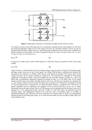
Figure (2) shows an asymmetric conventional cascaded inverter with two input voltage sources and 8
unidirectional power switches with antiparallel diode to supply inductive loads.](https://image.slidesharecdn.com/g042040045-150310022913-conversion-gate01/85/THD-Minimisation-for-Phase-Voltage-of-Multilevel-Inverters-Using-Genetic-Algorithm-2-320.jpg)
![ THD Minimisation for Phase Voltage of…
www.theijes.com The IJES Page 44
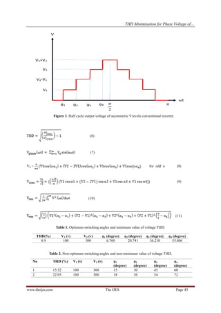
III. SIMULATION RESULTS
In this section, the inverter shown in Figure (2) is simulated based on the values shown in Table (1)
with the use of MATLAB/SIMULINK software. The inverter load is considered in an ohmic form with a value
of R=15Ω. Figure (4) shows the output voltage and Figure (5) shows the harmonic spectrum and the value of the
voltage waveform THD. As can be seen from these figures, the simulation results confirm the validation of the
proposed method advantages and its theoretical operation and control scheme.
0 0.01 0.02 0.03 0.04 0.05 0.06 0.07 0.08 0.09 0.1
-400
-300
-200
-100
0
100
200
300
400
time (S)
Vo(V)
Figure 4. Output voltage of asymmetric 9-level conventional inverter by using Table (1) data.
0 100 200 300 400 500 600 700 800 900 1000
0
0.5
1
1.5
2
2.5
3
3.5
Frequency (Hz)
Fundamental (50Hz) = 418.4 , THD= 8.91%
Mag(%ofFundamental)
Figure 5. Output voltage THD and harmonic spectrum.
IV. CONCLUTION
In this paper, for a 9-level cascaded inverter, optimized switching angles are obtained with the use of
genetic algorithm and the THD equation. The use of these values in switching, minimized voltage THD. This
method can be extended to various types of multilevel inverters and is simpler and cheaper compared to new
switching methods.
REFERENCES
[1] Honglin Zhou, Shuai Xiao, Geng Yang and Hua Geng, "Modeling and Control for a Bidirectional Buck–Boost Cascade
Inverter," IEEE TRANSACTIONS ON POWER ELECTRONICS, VOL. 27, NO. 3, pp. 1401-1413, 2012.
[2] Won-Kyun Choi and Feel-soon Kang, "H-bridge based Multilevel Inverter using PWM Switching Function," in Proc. INTELEC,
pp. 1-5, 2009.
[3] A.R. Beig and A. Dekka, "Experimental verification of multilevel inverter-based standalone power supply for low-voltage and
low-power applications," IET Power Electron., Vol. 5, Iss. 6, pp. 635–643, 2012.
[4] Jin Wang and Damoun Ahmadi, "A Precise and Practical Harmonic Elimination Method for Multilevel Inverters," IEEE
TRANSACTIONS ON INDUSTRY APPLICATIONS, VOL. 46, NO. 2, pp. 857-865, 2010.
[5] P. Palanivel and S.S. Dash, "Analysis of THD and output voltage performance for cascaded multilevel inverter using carrier
pulse width modulation techniques," IET Power Electron., Vol. 4, Iss. 8, pp. 951–958, 2011.
[6] Diorge A. B. Zambra, Cassiano Rech and José Renes Pinheiro, "Comparison of Neutral-Point-Clamped, Symmetrical, and
Hybrid Asymmetrical Multilevel Inverters," IEEE TRANSACTIONS ON INDUSTRIAL ELECTRONICS, VOL. 57, NO. 7, pp.
2297-2306, 2010.
[7] Ilhami Colak, Ersan Kabalci and Ramazan Bayindir, "Review of multilevel voltage source inverter topologies and control
schemes," Elsevier Journal of Energy Conversion and Management, Vol 52, pp. 1114–1128, 2011.
[8] Nabae A, Takashi I and Akagi H, "A new neutral-point clamped PWM inverter," IEEE Trans Ind Appl, Vol 17, pp. 518–23.1981.
[9] Meynard TA and Foch H, "Multi-level conversion: high voltage choppers and voltage-source inverters," In: Proceedings of IEEE
power electronics specialists conference, Toledo (Spain); 1992.](https://image.slidesharecdn.com/g042040045-150310022913-conversion-gate01/85/THD-Minimisation-for-Phase-Voltage-of-Multilevel-Inverters-Using-Genetic-Algorithm-5-320.jpg)