1) The document presents a study on using a radial basis function neural network (RBFNN) to compensate for drift in the stator currents of an induction motor under vector control. Stator current data with implemented errors was collected to train the RBFNN.
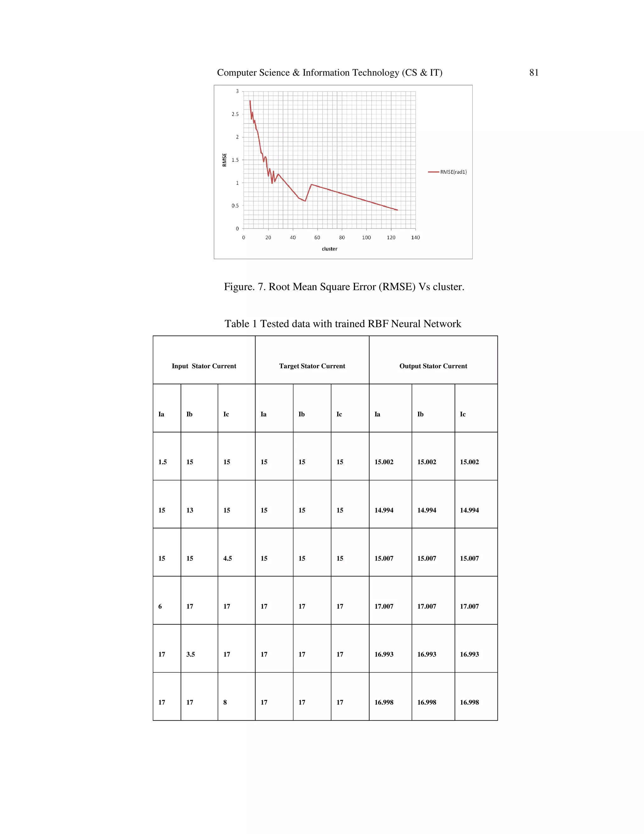
2) An RBFNN with 3 input, 125 hidden, and 3 output nodes trained on 960 data points achieved a root mean square error of 0.34525. When tested, the network was able to restore stator currents close to their original values, validating that it can compensate for drift.
3) Using an RBFNN with k-means clustering to select hidden nodes was able to learn the compensation behavior accurately from data and generalize
![76 Computer Science & Information Technology (CS & IT)
provide fast transient response [1]. Accurate position control is not possible with scalar control
since this requires instantaneous control of the torque. This requires either, instantaneous change
to the stator currents, which is not possible due to energy storage effects, or instantaneous change
to the rotor current which in the case of scalar control is controlled indirectly via the stator
currents. Similarly, whilst scalar control may provide acceptable steady state speed control,
precise and responsive speed control due to load changes requires accurate and responsive torque
control. The vector approach overcomes the sluggish transient response when using scalar control
of AC motors [7].
2. VECTOR CONTROL
Vector control of an Induction motor is also called Field orientation control. In a typical AC
induction motor, three alternating currents electrically displaced by 120◦ are applied to three
stationary stator coils of the motor. The resulting flux from the stator induces alternating currents
in the ‘squirrel cage’ conductors of the rotor to create its own field these fields interact to create
torque. Unlike a DC machine the rotor currents in an AC induction motor cannot be controlled
directly from an external source, but are derived from the interaction between the stator field and
the resultant currents induced in the rotor conductors [13].
Figure 1. Vector control of Induction motor
Vector control of an AC induction motor is analogous to the control of a separately excited DC
motor [7]. In a DC motor the field flux ψf produced by the field current If is perpendicular to the
armature flux ψa produced by the armature current Ia. These fields are decoupled and stationary
with respect to each other. Therefore when the armature current is controlled to control torque the
field flux remains unaffected enabling a fast transient response.
In a vector-controlled drive, the machine stator current vector Is has two components: ids or flux
component and iqs or torque component, as shown in the phasor diagram. These current
components are to be controlled independently, as in a dc machine, to control the flux and torque,
respectively. The ids is oriented in the direction of ψr, and iqs is oriented orthogonally to it. The
controller should make the two inverse transformations, where the unit vector cosθe and sinθe in
the controller should ensure correct alignment of ids in the direction of ψr and iqs at 90◦ ahead of it.
Obviously, the unit vector is the key element for vector control [8]. There are two methods of
vector control based on the derivation of the unit vector. These are the direct (or feedback)
method and indirect (or feed forward) method. For closed-loop flux control in constant-torque
and field weakening regions, ids can be controlled within the programmed flux control loop so that
the inverter always operates in PWM mode [1].](https://image.slidesharecdn.com/neuralnetworkbasedvectorcontrolofinductionmotor-131007040254-phpapp01/75/Neural-network-based-vector-control-of-induction-motor-2-2048.jpg)
![Computer Science & Information Technology (CS & IT) 77
3. DRIVE SYSTEM
It has been established that iq and id of the rotating reference frame must be controlled to provide
good dynamic control of the induction motor. Using closed loop control ordered quantities of iq
and id are compared with the actual values measured from the motor. In order to obtain the motor
values, transformations on the measured 3 phase stator currents into the direct and quadrature
components of the rotating reference frame are performed. The resulting error terms are then
transformed back to 3 phase quantities and applied to the motor.
Figure 2. Block diagram of Vector control of Induction motor
The power circuit (Fig.2) consists of a DC source (battery or rectifier DC), PWM IGBT inverter
and cage type induction motor. The signal processing blocks include machine phase current
sensors, signals computation and controller, and the PWM algorithm [3]. The command torque
(Te*) and stator flux (ψs*) generate the active (iqs*) and reactive (ids*) current commands within the
block which are then translated to generate input for PWM controller. The machine terminal
voltages and currents are sensed and converted into stationery frame ds – qs signals. These
signals are then converted to rotating frame. The synchronous control loops then generate Vqs*
and Vds* signals. Vqs* and Vds* signals are then translated using inverse Clarke transformation and
fed as input to PWM controller. The PWM controller receives signals at the input and translates
to gate drive signals for the IGBT inverter [8].
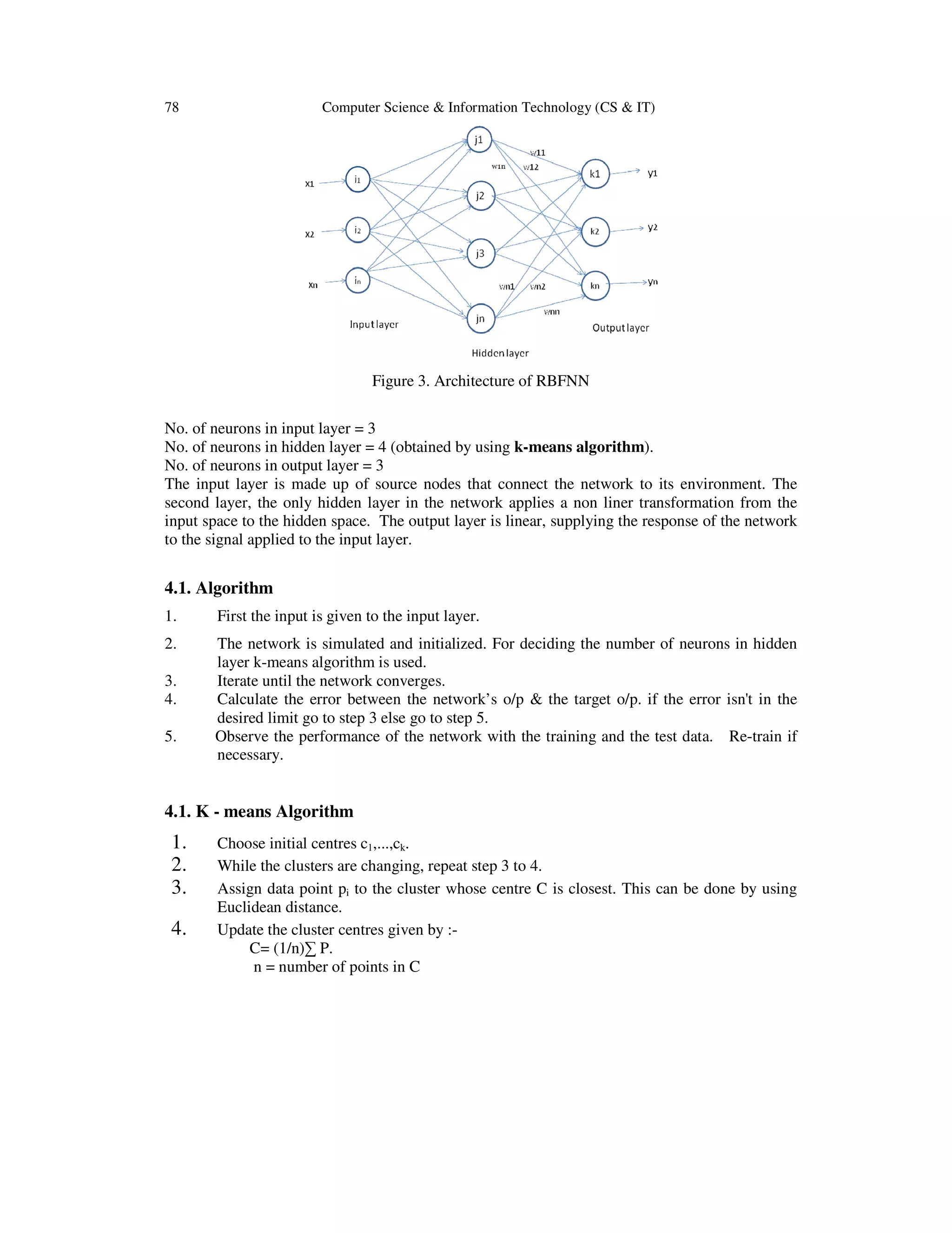
4. RADIAL BASIS FUNCTION NEURAL NETWORK
RBF is a Multilayer Perceptron Network (MLP) which is based on unit computing of non-linear
function of scalar product of input & output. For an auto associative net the training input and
target output vectors are identical. A stored vector can be retrieved from distorted or partial input
if the input is sufficiently similar to it. Auto-associative neural network is basically a feed
forward, fully-connected, multilayer perceptron (MLP) type neural network. The general RBF
network consists of 3 layers, Input layer, Hidden layer, Output layer.](https://image.slidesharecdn.com/neuralnetworkbasedvectorcontrolofinductionmotor-131007040254-phpapp01/75/Neural-network-based-vector-control-of-induction-motor-3-2048.jpg)
![82 Computer Science & Information Technology (CS & IT)
RBFNN was tested and the output shown in Table1 was obtained. It can be observed that the drift
in stator current due to various faults in all the three phases are compensated by the neural
network validating that trained neural network restores back the closest possible original value of
stator current achieving the compensation in the stator current of the Induction motor.
7. CONCLUSION
Vector control of Induction motor using Radial basis function neural network has been
implemented in this paper. The neural network was trained with 960 sets of input data and tested
to obtain a satisfactory output. The result of the K-MEANS algorithm was implemented in the
RBFNN and hence the stator currents were restored to its original values. In this paper,
supervised learning algorithm has been adopted to train the neural network. Artificial neural
network can be implemented by either using supervised network or fixed weight network or both
the types of network. By implementing the above said networks, performance of Induction motor
can be improved as any change in the stator current has been compensated by the trained neural
network and henceforth its performance.
REFERENCES
[1] A.K.Sharma,R.A.Gupta, Laxmi Srivastava.: Performance of ANN based indirect vector control
induction motor drive, Journal of theoritical and applied Information technology. IEEE trans 2007.
[2] M.H. Jokar, B. Abdi, M. Ardebili.: Vector Control of Induction Motors Using Radial Basis Function
Neural Network. (2007 IEEE trans.)
[3] L.Galotto, J.O.P. Pinto, B. Ozpineci, L.C.Leite, L.E. Borges da silva,: Sensor compensation in motor
drives using Kernel Regressio., IEEE International Electric Machines and drives conference,2007
[4] L. Galotto, Bimal. K. Bose, L.C. Leite, J.O.P. Pinto, L.E. Borges da silva, Germano Lambert-Torres.:
Auto-Associative Neural Network based sensor drift compensation in Indirect controlled drive
system. IEEE Industrial Electronics society,2007.
[5] Kamel Baddari, Tahar Aifa, Noureddine Djarfour, Jalal Ferahtia.:Application of Radial Basis
Function Artificial Neural Network to seismic data inversion. Science Direct Computers &
Geoscience 35,2009(2338-2344).
[6] A. El-Antably, L. Xiaogang and R. Martin.:System simulation of fault conditions in the components
of the electric drive system. IEEE journal 1993.
[7] N. Reitere, D. Roye and P. Mannevy.:Vector based investigation of induction motor drive under fault
operations. IEEE 1997
[8] Kramer. M .A.:Auto-associative Neural Networks. AIChE Journal, Vol.16
[9] X.Xu, R.N.De Donker and D.W.Novotny.: A stator flux oriented induction machine drive. IEEE 1998
[10] J.O.P.Pinto, B.K.Bose, L.E.Borges.: A stator flux oriented vector controlled induction motor drive
with space-vector PWM and flux vector synthesis by neural networks. IEEE trans. on Industry
Applications,Vol.37,No.5, 2001
[11] J.O.P.Pinto, B.K.Bose, L.E.Borges, and M.P.Kazmierkowski.: A neural network based space vector
PWM controller for voltage fed induction motor drive.IEEE trans. 2000.
[12] B.K.Bose,Ed.,Power Electronics and variable frequency drives, IEEE Press, New York, 1996.
[13] B.K.Bose., Modern Power Electronics and AC Drives, Prentice Hall, Upper Saddle River, NJ,2002](https://image.slidesharecdn.com/neuralnetworkbasedvectorcontrolofinductionmotor-131007040254-phpapp01/75/Neural-network-based-vector-control-of-induction-motor-8-2048.jpg)