Download to read offline
![International Research Journal of Engineering and Technology (IRJET) e-ISSN: 2395-0056
Volume: 05 Issue: 03 | Mar-2018 www.irjet.net p-ISSN: 2395-0072
© 2018, IRJET | Impact Factor value: 6.171 | ISO 9001:2008 Certified Journal | Page 2926
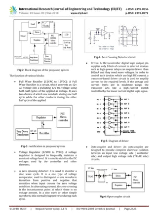
LCD: LCD (Liquid Crystal Display) screen is an
electronic display module and used to display the
operation of connected devices.
TRIAC: These are Static devices used to switching
operation. Static device is such device which
converts one type of energy or energy level into
another type of energy or energy level respectively
without any physical movement.
PIC Microcontroller: In our project we are using a
PIC microcontroller which has RISC (restricted
Instruction Set Codes) architecture due to which
controller requires only One Clock Cycle to
complete a single execution. In our project we are
using a 28 pin microcontroller having 16K/b of
FLASH ROM, 1.2K/b of RAM, and 256 bytes of
EPROM.
This controller having an inbuilt 10 Bit ADC which
requires to measure input and output analog
voltages. The operating cycle of PIC is of 200n/s.
The output port efficiency is to deliver 5v/40mA
on each port pins.
3. RESULT
The aim of our project is to prevent the power stealing, it
control the power via monitoring through microcontroller.
Our project will implementing when electricity supply
authority passed the high voltage (220-280) for few
minutes i.e, 2-3min, then power theft will be prevent by
setting the firing angle of TRIAC by using microcontroller.
In our project we give 220V-280V, after completing the
operation, the output voltage feed variable between 210-
240V across the load. The actual purpose of project is to be
controlling high voltage and converted into required
voltage.
Sr No Input voltage Output voltage
1. 280 238
2. 260 231
3. 240 210
Output tabale
4. CONCLUSION
Microcontroller based device which we design is easy to
implement and beneficial for both energy supply authority
and user. It also provide additional feature such as stabilize
the voltage, it meal a constant voltage. It also gives the
information of total load used in house on request at any
time. The statistical load used and profile can help user
manage their energy consumption. This system is secured
and decent because it can access by automatic operation.
This device has the efficiency to faced the high voltage and
feed the constant voltage to household appliances. This
device help to reduced the stolen of power by
implementing a high voltage through our system which
stabilize the voltage, whose consumer used electricity by
illegal hooking or bypassing the meter they will suffer by
this high voltage. As this device stabilizes only higher
voltage but by using active reactor in system, we can also
maintain the output voltage if input voltage drop down to
160V. It will completely eliminate the power theft and will
increase revenue for the government and save electricity.
REFERENCES
[1] Krunal Patel Electrical system, Centre of Excellence
Raychem Innovation Centre, Raychem RPG Pvt. Ltd. Halol,
Gujarat, India
[2] Muhammad Tariq is with the Electrical Engineering
Department, Princeton University, NJ, USA, 08544. IEEE
Transaction on smart grid (volume: PP, Issue: 99), 25
August 201
[3] J. Nagi, K. S. Yap, S.K. Tiong, S. K. Ahmed, Malik
Mohomad, “Non Technical Loss Detection for Metered
consumer using support vector machine”, IEEE transaction
on Power Delivery, Vol.25,April 2010
[4] Shailesh Sankpal / Omkar Kadam Electrical
Engineering Department, Sanjeevan Engineering and
Technology, Panhala, Maharashtra, IEEE, 07 May 2015
[5] Gruhesh Swaminatham ;Maheedar Subramanian
;Pravin Thangaraj “Distribution Line Monitoring Detection
of Power Theft Using Power Line Communication”, Energy
Conversion (CENCON), 2014 IEEE Conference Date: 13-15
Oct 2014](https://image.slidesharecdn.com/irjet-v5i3670-190131103644/85/IRJET-Power-Stolen-Prevention-by-using-PIC16882-Microcontroller-3-320.jpg)

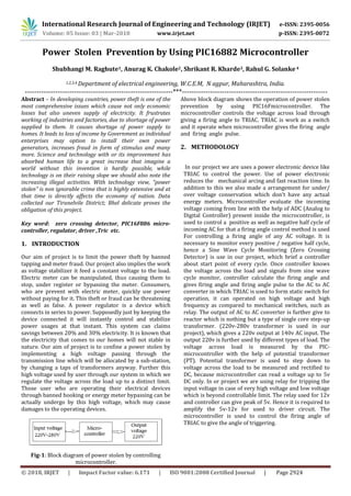
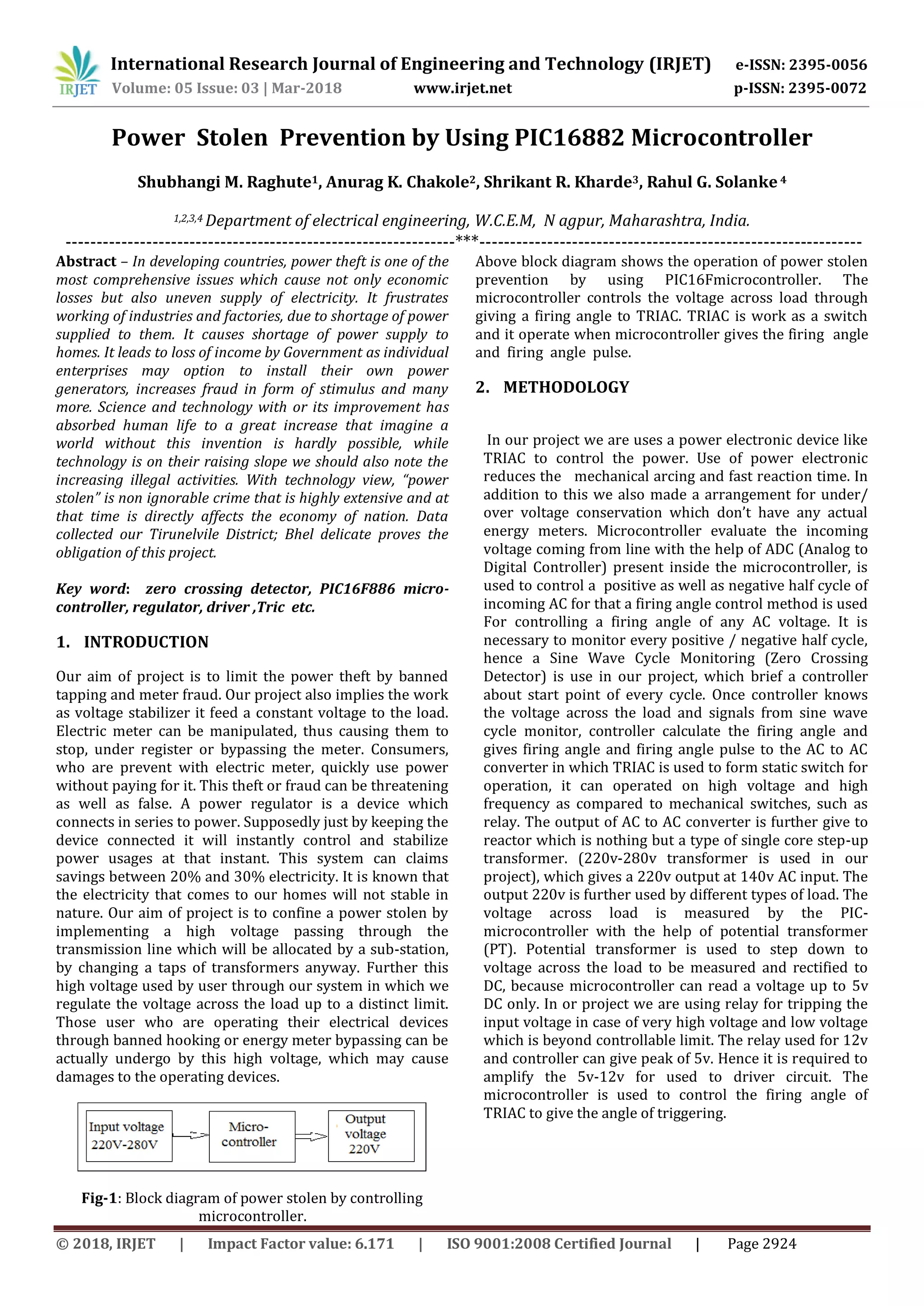
This document describes a system to prevent power theft using a PIC16F886 microcontroller. The system monitors the input voltage and uses a TRIAC triggered by the microcontroller to regulate the output voltage supplied to loads. It aims to limit power theft by cutting off power to loads that are illegally connected. The microcontroller calculates the firing angle for the TRIAC based on input from a zero-crossing detector and potential transformer. This allows it to stabilize the output voltage between 210-240V even when the input voltage varies from 280V to 220V. The system provides over and under voltage protection and could help reduce power theft and losses for utilities by up to 30%.