
![LOOP ANTENNA
RADIATED FIELDS
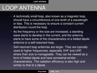
Since the radiated fields are usually determined in spherical
components, the rectangular unit vectors of (2) are transformed
to spherical unit vectors.
ax = arsinθcosφ + aθcosθcosφ + aφsinφ (6)
ay = arsinθsinφ + aθcosθsinφ + aφcosφ (7)
az = arcosθ − aθsinφ (8)
Substituting (3,4,5,6,7,8) in (2) reduces it to:
Ie = ar[Iρsinθcos(φ − φ ) + Iφsinθsin(φ − φ ) + Izcosθ] +
aθ[Iρcosθcos(φ − φ ) + Iφcosθsin(φ − φ ) − Izsinθ] +
aφ[−Iρsin(φ − φ ) + Iφcos(φ − φ )]
Priya Hada Title 8/19](https://image.slidesharecdn.com/presentationsmallloopantennaselectricfieldanddirectivitycalculationssectionb-140510070434-phpapp02/85/Presentation-small-loop_antennas_electric_field_and_directivity_calculations_section_b-8-320.jpg)
![LOOP ANTENNA
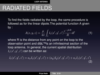
RADIATED FIELDS
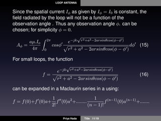
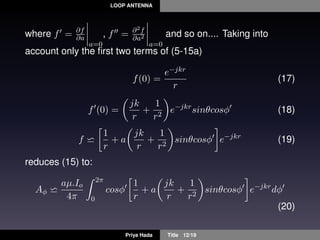
For the circular loop, the current is flowing in the φ direction (Iφ)
so that above equation reduces to:
Ie = ar[Iφsinθsin(φ−φ )]+aθ[Iφcosθsin(φ−φ )]+aφ[Iφcos(φ−φ )]
(9)
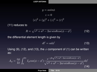
The distance R, from any point on the loop to the observation
point, can be written as:
R = (x − x )2 + (y − y )2 + (z − z )2 (10)
x = rsinθcosφ
y = rsinθsinφ
z = rcosθ
x2
+ y2
+ z2
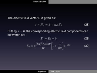
= r (11)
x = acosφ
Priya Hada Title 9/19](https://image.slidesharecdn.com/presentationsmallloopantennaselectricfieldanddirectivitycalculationssectionb-140510070434-phpapp02/85/Presentation-small-loop_antennas_electric_field_and_directivity_calculations_section_b-9-320.jpg)
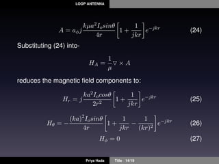
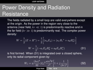

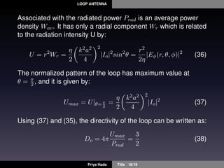

The document presents information on loop antennas. It discusses that a loop antenna consists of a loop of wire that carries RF current. It describes loop antennas as either electrically small or large based on circumference size. For a small circular loop antenna, it derives expressions for the electric and magnetic fields radiated using cylindrical coordinates. It finds that the power radiated from a small loop is proportional to the fourth power of its radius. It also determines the directivity and maximum effective area of a circular loop antenna.


