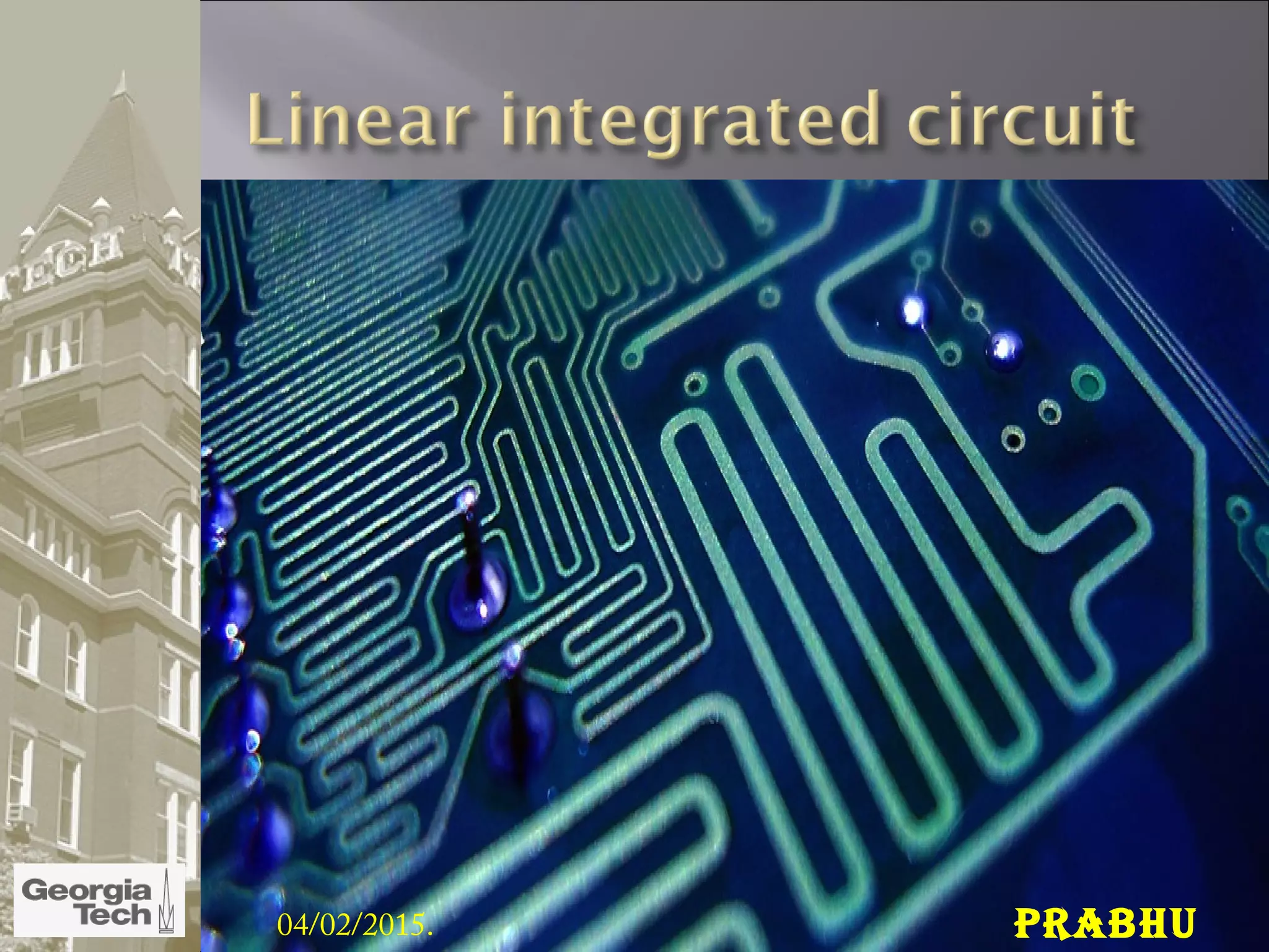
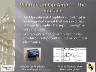
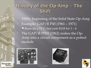
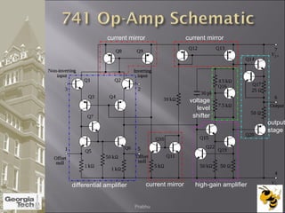
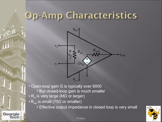
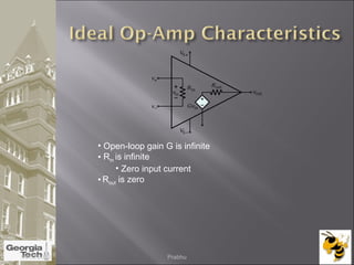
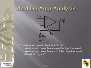
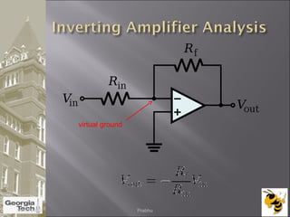
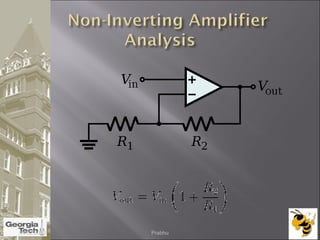
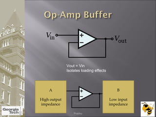
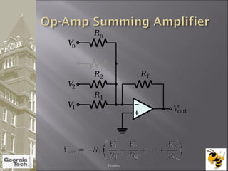
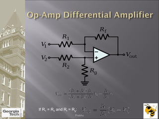
04/02/2015. Prabhu
 An Operational Amplifier (Op-Amp) is
an integrated circuit that uses external
voltage to amplify the input through a
very high gain.
 We recognize an Op-Amp as a mass-
produced component found in countless
electronics.
What an Op-Amp looks
like to a lay-person
What an Op-Amp looks
like to an engineer04/02/2015 Prabhu
 There are 8 pins in a common Op-Amp,
like the 741 which is used in many
instructional courses.
04/02/2015 Prabhu
 The actual count varies, but an Op-Amp
contains several Transistors, Resistors,
and a few Capacitors and Diodes.
 For simplicity, an Op-Amp is often
depicted as this:
Non-
Inverting
Input
Inverting
Input
Positive
Power
Supply
Negative
Power
Supply
Output
-
+
04/02/2015 Prabhu
 Before the Op-Amp: Harold S. Black
develops the feedback amplifier for the
Western Electric Company (1920-1930)
A
β
Input Output
Forward Gain
Feedback
04/02/2015 Prabhu
 The end of Vacuum Tubes was built up
during the 1950’s-1960’s to the advent of
solid-state electronics
1. The Transistor
2. The Integrated Circuit
3. The Planar Process
04/02/2015 Prabhu
 1960s: beginning of the Solid State Op-Amp
 Example: GAP/R P45 (1961 – 1971)
 Runs on ± 15 V, but costs $118 for 1 – 4
 The GAP/R PP65 (1962) makes the Op-
Amp into a circuit component as a potted
module
04/02/2015 Prabhu
 The gain of the Op-Amp itself is calculated as:
G = Vout/(V+ – V-)
 The maximum output is the power supply
voltage
 When used in a circuit, the gain of the circuit (as
opposed to the op-amp component) is:
Av = Vout/Vin
04/02/2015 Prabhu
 As mentioned
earlier, the
maximum output
value is the
supply voltage,
positive and
negative.
 The gain (G) is
the slope
between
saturation points.
Vout
Vin
Vs
-
Vs
+
04/02/2015 Prabhu
differential amplifier high-gain amplifier
voltage
level
shifter
output
stage
current mirror
current mirror current mirror
04/02/2015 Prabhu
• Open-loop gain G is typically over 9000
• But closed-loop gain is much smaller
• Rin is very large (MΩ or larger)
• Rout is small (75Ω or smaller)
• Effective output impedance in closed loop is very small
04/02/2015 Prabhu
• Open-loop gain G is infinite
• Rin is infinite
• Zero input current
• Rout is zero
04/02/2015 Prabhu
To analyze an op-amp feedback circuit:
• Assume no current flows into either input terminal
• Assume no current flows out of the output terminal
• Constrain: V+ = V-
04/02/2015 Prabhu
virtual ground
04/02/2015 Prabhu
04/02/2015 Prabhu
Vout = Vin
Isolates loading effects
A
High output
impedance
B
Low input
impedance
04/02/2015 Prabhu
04/02/2015 Prabhu
If R1 = R2 and Rf = Rg:
04/02/2015 Prabhu
Filters
Types:
•Low pass filter
•High pass filter
•Band pass filter
•Cascading (2 or more filters connected
together)
R2
+
-
+
V0
__
+ Vcc
- Vcc
-
+
R1
C
Low pass
filter
Low pass filter Cutoff
frequency 
Low pass filter transfer
function
04/02/2015 Prabhu
 Electrocardiograph (ECG) Amplification
 Need to measure difference in voltage from lead 1 and
lead 2
 60 Hz interference from electrical equipment
04/02/2015 Prabhu
 Piezoelectric Transducer
 Used to measure force, pressure, acceleration
 Piezoelectric crystal generates an electric charge
in response to deformation
 Use Charge Amplifier
 Just an integrator op-amp circuit
04/02/2015 Prabhu

Linear intergrated circuit

  • 1.
  • 2.
     An OperationalAmplifier (Op-Amp) is an integrated circuit that uses external voltage to amplify the input through a very high gain.  We recognize an Op-Amp as a mass- produced component found in countless electronics. What an Op-Amp looks like to a lay-person What an Op-Amp looks like to an engineer04/02/2015 Prabhu
  • 3.
     There are8 pins in a common Op-Amp, like the 741 which is used in many instructional courses. 04/02/2015 Prabhu
  • 4.
     The actualcount varies, but an Op-Amp contains several Transistors, Resistors, and a few Capacitors and Diodes.  For simplicity, an Op-Amp is often depicted as this: Non- Inverting Input Inverting Input Positive Power Supply Negative Power Supply Output - + 04/02/2015 Prabhu
  • 5.
     Before theOp-Amp: Harold S. Black develops the feedback amplifier for the Western Electric Company (1920-1930) A β Input Output Forward Gain Feedback 04/02/2015 Prabhu
  • 6.
     The endof Vacuum Tubes was built up during the 1950’s-1960’s to the advent of solid-state electronics 1. The Transistor 2. The Integrated Circuit 3. The Planar Process 04/02/2015 Prabhu
  • 7.
     1960s: beginningof the Solid State Op-Amp  Example: GAP/R P45 (1961 – 1971)  Runs on ± 15 V, but costs $118 for 1 – 4  The GAP/R PP65 (1962) makes the Op- Amp into a circuit component as a potted module 04/02/2015 Prabhu
  • 8.
     The gainof the Op-Amp itself is calculated as: G = Vout/(V+ – V-)  The maximum output is the power supply voltage  When used in a circuit, the gain of the circuit (as opposed to the op-amp component) is: Av = Vout/Vin 04/02/2015 Prabhu
  • 9.
     As mentioned earlier,the maximum output value is the supply voltage, positive and negative.  The gain (G) is the slope between saturation points. Vout Vin Vs - Vs + 04/02/2015 Prabhu
  • 10.
    differential amplifier high-gainamplifier voltage level shifter output stage current mirror current mirror current mirror 04/02/2015 Prabhu
  • 11.
    • Open-loop gainG is typically over 9000 • But closed-loop gain is much smaller • Rin is very large (MΩ or larger) • Rout is small (75Ω or smaller) • Effective output impedance in closed loop is very small 04/02/2015 Prabhu
  • 12.
    • Open-loop gainG is infinite • Rin is infinite • Zero input current • Rout is zero 04/02/2015 Prabhu
  • 13.
    To analyze anop-amp feedback circuit: • Assume no current flows into either input terminal • Assume no current flows out of the output terminal • Constrain: V+ = V- 04/02/2015 Prabhu
  • 14.
  • 15.
  • 16.
    Vout = Vin Isolatesloading effects A High output impedance B Low input impedance 04/02/2015 Prabhu
  • 17.
  • 18.
    If R1 =R2 and Rf = Rg: 04/02/2015 Prabhu
  • 19.
    Filters Types: •Low pass filter •Highpass filter •Band pass filter •Cascading (2 or more filters connected together) R2 + - + V0 __ + Vcc - Vcc - + R1 C Low pass filter Low pass filter Cutoff frequency  Low pass filter transfer function 04/02/2015 Prabhu
  • 20.
     Electrocardiograph (ECG)Amplification  Need to measure difference in voltage from lead 1 and lead 2  60 Hz interference from electrical equipment 04/02/2015 Prabhu
  • 21.
     Piezoelectric Transducer Used to measure force, pressure, acceleration  Piezoelectric crystal generates an electric charge in response to deformation  Use Charge Amplifier  Just an integrator op-amp circuit 04/02/2015 Prabhu