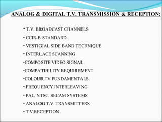
The document discusses analog television transmission and reception. It covers topics such as:
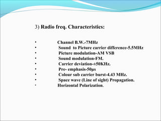
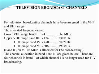
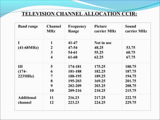
- TV broadcast channel allocation standards and frequencies
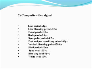
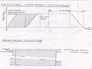
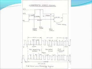
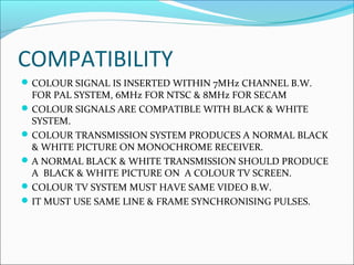
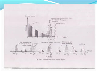
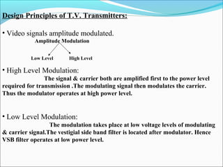
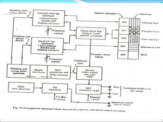
- Analog TV signal parameters including video scanning, signal bandwidths, and modulation techniques
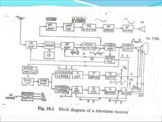
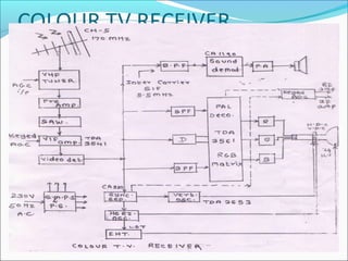
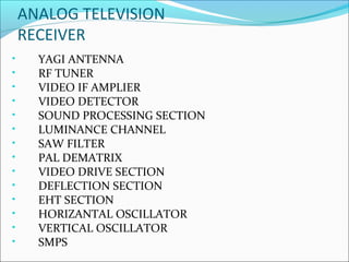
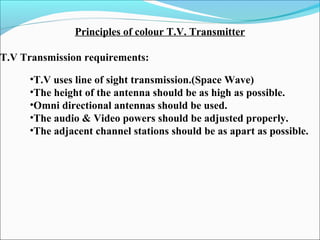
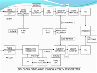
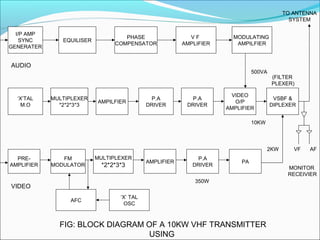
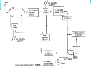
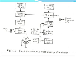
- Components of analog TV transmitters and receivers such as tuners, amplifiers, detectors and more
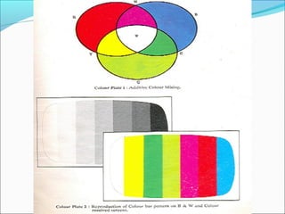
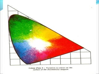
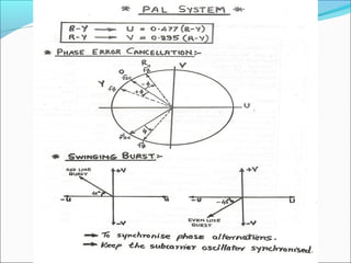
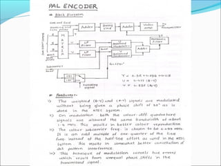
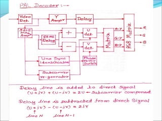
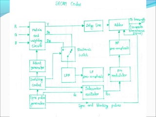
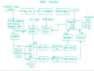
- Color TV fundamentals including color encoding and transmission systems like PAL, NTSC, and SECAM
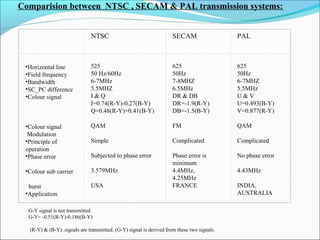
- A comparison of the features of different analog color TV transmission standards
This presentation is focused on basic understanding of video signal generation and its electronic interpretation. Contents are taken from bible of television!
This presentation is dedicated to R R Gulati.
Basics of Colour Television and Digital TVjanakiravi
Main characteristics of human eye with regard to perception of colours-mixing of colours. three standards of colour transmission system, CATV, DTH, HDTV & SMART TV
For TS-SBTET, C-18, DECE 6 Unit, By Nenavath Ravi Kumar, MIST Hyderabad
Keypad is a common interface with any microcontroller. This presentation gives details of keypad can be interfaced with 8051. The key pressed may be dispalyed on LCD/7 segment/LED displays.
This presentation has given a brief introduction and working of CMOS Logic Structures which includes MOS logic, CMOS logic, CMOS logic structure, CMOS complementary logic, pass transistor logic, bi CMOS logic, pseudo –nMOS logic, CMOS domino logic, Cascode Voltage Switch Logic(CVSL), clocked CMOS logic(c²mos), dynamic CMOS logic
Television Standards and systems: Components of a TV system –interlacing – composite video signal. Colour TV – Luminance and Chrominance signal; Monochrome and Colour Picture Tubes – Colour TV systems–NTSC, PAL, SECAM-Components of a Remote Control and TV camera tubes, HDTV, LED and LCD TVs, DTH TV.
Main constraint for colour TV was compatibility with existing monochrome system. It should produce normal black and white picture on monochrome receiver without any modification on receiver circuitry. Moreover colour receiver must produce a black and white picture if transmission is monochrome.
Hence it should have same - bandwidth, location & spacing of sound and video frequencies, luminance information as a monochromatic signal. Colour information in signal should not effect picture on a monochrome receiver. Other circuit details of colour receiver should be same as that of monochromatic receiver..
it is a indtoduction about the analog television, we learn in this slides how can analog television work and when it is use with fequancy band it is need also we will learn about the frame, PAL NTSC and SECAM these tech. are suit for analog television with two systems that 625 line and 525 lines. in this seminer we can learn about the flicking and the finite beam fly-back time , learn about odd and even fields and why we sued them
Discusses basic television broadcasting system and standards. Explains TV transmission principles used in Broadcasting. Modulation type and advantage of negative modulation. Explains VSB modulation in TV transmitters.
CFD Simulation of By-pass Flow in a HRSG module by R&R Consult.pptxR&R Consult
CFD analysis is incredibly effective at solving mysteries and improving the performance of complex systems!
Here's a great example: At a large natural gas-fired power plant, where they use waste heat to generate steam and energy, they were puzzled that their boiler wasn't producing as much steam as expected.
R&R and Tetra Engineering Group Inc. were asked to solve the issue with reduced steam production.
An inspection had shown that a significant amount of hot flue gas was bypassing the boiler tubes, where the heat was supposed to be transferred.
R&R Consult conducted a CFD analysis, which revealed that 6.3% of the flue gas was bypassing the boiler tubes without transferring heat. The analysis also showed that the flue gas was instead being directed along the sides of the boiler and between the modules that were supposed to capture the heat. This was the cause of the reduced performance.
Based on our results, Tetra Engineering installed covering plates to reduce the bypass flow. This improved the boiler's performance and increased electricity production.
It is always satisfying when we can help solve complex challenges like this. Do your systems also need a check-up or optimization? Give us a call!
Work done in cooperation with James Malloy and David Moelling from Tetra Engineering.
More examples of our work https://www.r-r-consult.dk/en/cases-en/
Student information management system project report ii.pdfKamal Acharya
Our project explains about the student management. This project mainly explains the various actions related to student details. This project shows some ease in adding, editing and deleting the student details. It also provides a less time consuming process for viewing, adding, editing and deleting the marks of the students.
Cosmetic shop management system project report.pdfKamal Acharya
Buying new cosmetic products is difficult. It can even be scary for those who have sensitive skin and are prone to skin trouble. The information needed to alleviate this problem is on the back of each product, but it's thought to interpret those ingredient lists unless you have a background in chemistry.
Instead of buying and hoping for the best, we can use data science to help us predict which products may be good fits for us. It includes various function programs to do the above mentioned tasks.
Data file handling has been effectively used in the program.
The automated cosmetic shop management system should deal with the automation of general workflow and administration process of the shop. The main processes of the system focus on customer's request where the system is able to search the most appropriate products and deliver it to the customers. It should help the employees to quickly identify the list of cosmetic product that have reached the minimum quantity and also keep a track of expired date for each cosmetic product. It should help the employees to find the rack number in which the product is placed.It is also Faster and more efficient way.
Democratizing Fuzzing at Scale by Abhishek Aryaabh.arya
Presented at NUS: Fuzzing and Software Security Summer School 2024
This keynote talks about the democratization of fuzzing at scale, highlighting the collaboration between open source communities, academia, and industry to advance the field of fuzzing. It delves into the history of fuzzing, the development of scalable fuzzing platforms, and the empowerment of community-driven research. The talk will further discuss recent advancements leveraging AI/ML and offer insights into the future evolution of the fuzzing landscape.
Immunizing Image Classifiers Against Localized Adversary Attacksgerogepatton
This paper addresses the vulnerability of deep learning models, particularly convolutional neural networks
(CNN)s, to adversarial attacks and presents a proactive training technique designed to counter them. We
introduce a novel volumization algorithm, which transforms 2D images into 3D volumetric representations.
When combined with 3D convolution and deep curriculum learning optimization (CLO), itsignificantly improves
the immunity of models against localized universal attacks by up to 40%. We evaluate our proposed approach
using contemporary CNN architectures and the modified Canadian Institute for Advanced Research (CIFAR-10
and CIFAR-100) and ImageNet Large Scale Visual Recognition Challenge (ILSVRC12) datasets, showcasing
accuracy improvements over previous techniques. The results indicate that the combination of the volumetric
input and curriculum learning holds significant promise for mitigating adversarial attacks without necessitating
adversary training.
Overview of the fundamental roles in Hydropower generation and the components involved in wider Electrical Engineering.
This paper presents the design and construction of hydroelectric dams from the hydrologist’s survey of the valley before construction, all aspects and involved disciplines, fluid dynamics, structural engineering, generation and mains frequency regulation to the very transmission of power through the network in the United Kingdom.
Author: Robbie Edward Sayers
Collaborators and co editors: Charlie Sims and Connor Healey.
(C) 2024 Robbie E. Sayers
NO1 Uk best vashikaran specialist in delhi vashikaran baba near me online vas...Amil Baba Dawood bangali
Contact with Dawood Bhai Just call on +92322-6382012 and we'll help you. We'll solve all your problems within 12 to 24 hours and with 101% guarantee and with astrology systematic. If you want to take any personal or professional advice then also you can call us on +92322-6382012 , ONLINE LOVE PROBLEM & Other all types of Daily Life Problem's.Then CALL or WHATSAPP us on +92322-6382012 and Get all these problems solutions here by Amil Baba DAWOOD BANGALI
#vashikaranspecialist #astrologer #palmistry #amliyaat #taweez #manpasandshadi #horoscope #spiritual #lovelife #lovespell #marriagespell#aamilbabainpakistan #amilbabainkarachi #powerfullblackmagicspell #kalajadumantarspecialist #realamilbaba #AmilbabainPakistan #astrologerincanada #astrologerindubai #lovespellsmaster #kalajaduspecialist #lovespellsthatwork #aamilbabainlahore#blackmagicformarriage #aamilbaba #kalajadu #kalailam #taweez #wazifaexpert #jadumantar #vashikaranspecialist #astrologer #palmistry #amliyaat #taweez #manpasandshadi #horoscope #spiritual #lovelife #lovespell #marriagespell#aamilbabainpakistan #amilbabainkarachi #powerfullblackmagicspell #kalajadumantarspecialist #realamilbaba #AmilbabainPakistan #astrologerincanada #astrologerindubai #lovespellsmaster #kalajaduspecialist #lovespellsthatwork #aamilbabainlahore #blackmagicforlove #blackmagicformarriage #aamilbaba #kalajadu #kalailam #taweez #wazifaexpert #jadumantar #vashikaranspecialist #astrologer #palmistry #amliyaat #taweez #manpasandshadi #horoscope #spiritual #lovelife #lovespell #marriagespell#aamilbabainpakistan #amilbabainkarachi #powerfullblackmagicspell #kalajadumantarspecialist #realamilbaba #AmilbabainPakistan #astrologerincanada #astrologerindubai #lovespellsmaster #kalajaduspecialist #lovespellsthatwork #aamilbabainlahore #Amilbabainuk #amilbabainspain #amilbabaindubai #Amilbabainnorway #amilbabainkrachi #amilbabainlahore #amilbabaingujranwalan #amilbabainislamabad
Sachpazis:Terzaghi Bearing Capacity Estimation in simple terms with Calculati...Dr.Costas Sachpazis
Terzaghi's soil bearing capacity theory, developed by Karl Terzaghi, is a fundamental principle in geotechnical engineering used to determine the bearing capacity of shallow foundations. This theory provides a method to calculate the ultimate bearing capacity of soil, which is the maximum load per unit area that the soil can support without undergoing shear failure. The Calculation HTML Code included.
2. ANALOG & DIGITAL T.V. TRANSMISSION & RECEPTION:
• T.V. BROADCAST CHANNELS
• CCIR-B STANDARD
• VESTIGIAL SIDE BAND TECHNIQUE
• INTERLACE SCANNING
•COMPOSITE VIDEO SIGNAL
•COMPATIBILITY REQUIREMENT
•COLOUR TV FUNDAMENTALS.
• FREQUENCY INTERLEAVING
• PAL, NTSC, SECAM SYSTEMS
• ANALOG T.V. TRANSMITTERS
• T.V.RECEPTION
3. TELEVISION BROADCAST CHANNELS
For television broadcasting channels have been assigned in the VHF
and UHF range.
The allocated frequencies are:
Lower VHF range band I - 41…………68 MHz.
Upper VHF range band III - 174………230MHz.
UHF range band IV - 470………582MHz.
UHF range band V - 606………790MHz.
(Band II , 88 to 108 MHz is allocated for FM broadcasting )
The channel allocation in band I and III are given below. There are
four channels in band I, of which channel I is no longer used for T. V.
broadcasting.
4. TELEVISION CHANNEL ALLOCATION CCIR:
Band range Channel
MHz
Frequency
Range
Picture
carrier MHz
Sound
carrier MHz
I
(41-68MHz)
1
2
3
4
41-47
47-54
54-61
61-68
Not in use
48.25
55.25
62.25
53.75
60.75
67.75
III
(174-
223MHz)
5
6
7
8
9
10
174-181
181-188
188-195
195-203
202-209
209-216
175.25
182.25
189.25
169.25
203.25
210.25
180.75
187.75
194.75
201.75
208.75
215.75
Additional
channel
11
12
216.23
223.23
217.25
224.25
222.75
229.75
5. CCIR-B Standard
1) Video characteristics:
Number of lines/picture-625
Interlace ratio-2:1
Scanning sequence for lines-left to right
Scanning sequence for field-Top to bottom
Field freq-50 fields/sec
Line freq-15625 Hz
Aspect ratio-4:3
Video bandwidth-5 MHz
Vertical resolution-0.7 x (625-40)=409lines.
Horizontal resolution =[410 x (4/3)]=546
alternate Black & white lines.
6. 2) Composite video signal:
• Line period-64μs
• Line blanking period-12μs
• Front porch-1.5μs
• Back porch-5.8μs
• Sync pulse period-4.7μs
• Post and pre equalizing pulse-160μs
• Vertical blanking pulse-1280μs
• Field period-20ms
• Sync level-100%
• Blanking level-75%
• White level-10%
7. 3) Radio freq. Characteristics:
• Channel B.W.-7MHz
• Sound to Picture carrier difference-5.5MHz
• Picture modulation-AM VSB
• Sound modulation-FM.
• Carrier deviation-±50KHz.
• Pre- emphasis-50μs
• Colour sub carrier burst-4.43 MHz.
• Space wave (Line of sight) Propagation.
• Horizontal Polarization.
8.
9.
10.
11. COMPATIBILITY
COLOUR SIGNAL IS INSERTED WITHIN 7MHz CHANNEL B.W.
FOR PAL SYSTEM, 6MHz FOR NTSC & 8MHz FOR SECAM
COLOUR SIGNALS ARE COMPATIBLE WITH BLACK & WHITE
SYSTEM.
COLOUR TRANSMISSION SYSTEM PRODUCES A NORMAL BLACK
& WHITE PICTURE ON MONOCHROME RECEIVER.
A NORMAL BLACK & WHITE TRANSMISSION SHOULD PRODUCE
A BLACK & WHITE PICTURE ON A COLOUR TV SCREEN.
COLOUR TV SYSTEM MUST HAVE SAME VIDEO B.W.
IT MUST USE SAME LINE & FRAME SYNCHRONISING PULSES.
12. COLOUR TV FUNDAMENTALS
GRASSMAN’S LAW
LUMINANCE OR BRIGHTNESS, HUE & SATURATION
CHROMACITY DIAGRAM
MIXING OF COLOUR
1. ADDITIVE MIXING
2. SUBTRACTIVE MIXING
COLOUR DIFFERENCE
13.
14.
15.
16.
17. ANALOG TELEVISION
RECEIVER
• YAGI ANTENNA
• RF TUNER
• VIDEO IF AMPLIER
• VIDEO DETECTOR
• SOUND PROCESSING SECTION
• LUMINANCE CHANNEL
• SAW FILTER
• PAL DEMATRIX
• VIDEO DRIVE SECTION
• DEFLECTION SECTION
• EHT SECTION
• HORIZANTAL OSCILLATOR
• VERTICAL OSCILLATOR
• SMPS
18. RF TUNER:
It selects the channel to be received by switching pre-tuned circuits in the RF
stage in the oscillator.
It matches the impedance of the line at its i/p and amplifies it to maintain a
good signal to noise ratio.
It converts the RF into IF by mixing with the local oscillator frequency to feed
it to the VIF amplifier.
MULTISTAGE VIF AMPLIFIER:
Used in conjunction with a surface acoustic wave(SAW) filter and a preamp to
obtain a high controlled gain (upto 80db).
For VSB reception, it amplifies picture if (38.9MHz), COLOUR SUBCARRIER
IF(34.47mhz) at 50% and SOUND IF(33.4 MHz) AT 5 – 10% of the peak
amplification between the 35-38MHz range.
The last stage feeds into a video detector
VIDEO DETECTOR
It extracts the video signal from the modulated IF signal.A diode detector is
commonly used to demodulate the amplitude modulated video if signal by
rectification.
Due to non linearities in the simple diode detectors,synchronous
demodulators or balanced multipliers are used in modern receivers.
19. SYNCHRONOUS VIDEO IF DETECTION
It works on the sampling principle to overcome nonlinearities and harmonics.The
amplitude modulation is detected at the sampling intervals by limiting the carrier
and selecting the pure carrier by tuned resonant ckts.The video modulated signal
carrier is sampled by a pure unmodulated carrier of exactly the same
frequency.The phase relation between the reference carrier and modulated signal
are vital for detection
SOUND SEPERATION AND PROCESSING
The SOUND IF signal at 33.4MHz is taken off at the output of the second VIDEO
I.F. Stage by means of a tuned circuit which feeds into a diode detector. The VIF
and SIF are heterodyned in this detector to produce different frequency as the
intercarrier SIF at 5.5MHz.The composite colour video signal is amplified and
passed on to the luminance channel for amplification of the monochrome Y
signal,and to the chroma section for decoding and further processing of the
chrominance signal.
LUMINANCE CHANNEL
It provides normal video amplification for monochrome signals with facility of
contrast adjustment by the amplifier gain control and brightness adjustment by
suitable bias variation of picture tube.It has to incorporate a delay line to keep the
luminance signal in step with the chrominance signal.A notch filter is used to
block the colour sub carrier(4.43MHz) which would otherwise cause dot pattern
interference.
20. .
SYNCHRONOUS DETECTION
The U & V signals from the pal dematrix are applied to two synchronous
demodulators ,it passes only the signals that are in phase with the two quadrature
phased with the two quadrature phased reference subcarrier signals . The colour
burst signal required to synchronise the locally generated sub carriers separated
from the CVS.
21. VIDEO DRIVE SECTION:
The U & V signals obtained at the output of the synchronous detectors are
amplified by the relative gain factor of 1.140 for V channel to get back the (R-Y),and
2.028 for U channel to (B-Y).
The (G-Y) is obtained by matrixing (R-Y) &(B-Y).The three colours reclamped to
get the maximum black and the luminance.
DEFLECTION CIRCUITS:
Sync separation synchronization of the horizontal and the vertical oscillator that
drive the horizontal and vertical coils ,generation of the EHT the focus anode
and other auxiliary voltages and blanking during fly back are provided by
deflection ckts
Degaussing coils are provided for removing stay colouring effects on the screen
caused by stray magnetic field.
28. Comparision between NTSC , SECAM & PAL transmission systems:
NTSC SECAM PAL
•Horizontal line
•Field frequency
•Bandwidth
•SC_PC difference
•Colour signal
•Colour signal
Modulation
•Principle of
operation
•Phase error
•Colour sub carrier
burst
•Application
525
50 Hz/60Hz
6-7MHz
5.5MHZ
I & Q
I=0.74(R-Y)-0.27(B-Y)
Q=0.48(R-Y)+0.41(B-Y)
QAM
Simple
Subjected to phase error
3.579MHz
USA
625
50Hz
7-8MHZ
6.5MHz
DR & DB
DR=-1.9(R-Y)
DB=-1.5(B-Y)
FM
Complicated
Phase error is
minimum
4.4MHz,
4.25MHz
FRANCE
625
50Hz
6-7MHZ
5.5MHz
U & V
U=0.493(B-Y)
V=0.877(R-Y)
QAM
Complicated
No phase error
4.43MHz
INDIA,
AUSTRALIA
G-Y signal is not transmitted.
G-Y= -0.51(R-Y)-0.186(B-Y)
(R-Y) & (B-Y) signals are transmitted. (G-Y) signal is derived from these two signals.
29. Principles of colour T.V. Transmitter
T.V Transmission requirements:
•T.V uses line of sight transmission.(Space Wave)
•The height of the antenna should be as high as possible.
•Omni directional antennas should be used.
•The audio & Video powers should be adjusted properly.
•The adjacent channel stations should be as apart as possible.
30. Design Principles of T.V. Transmitters:
• Video signals amplitude modulated.
Amplitude Modulation
Low Level High Level
• High Level Modulation:
The signal & carrier both are amplified first to the power level
required for transmission .The modulating signal then modulates the carrier.
Thus the modulator operates at high power level.
• Low Level Modulation:
The modulation takes place at low voltage levels of modulating
& carrier signal.The vestigial side band filter is located after modulator. Hence
VSB filter operates at low power level.
33. SR
NO.
PARAMETERS LOW LEVEL
MODULATION
HIGH LEVEL
MODULATION
1 POINT AT
WHICH
MODULATION
TAKES PLACE
MODULATION TAKES
PLACE IN THE INITIAL
STAGES OF
AMPLIFICATION
MODULATION TAKES
PLACE IN THE FINAL
STAGE OF
AMPLIFICATION.
2 POWER
LEVEL
MODULATION
CIRCUITARY HAS TO
HANDLE LOW POWER
MODULATION
CIRCUITARY HAS TO
HANDLE HIGH POWER
3 COMPLEXITY MODULATION
CIRCUITARY IS SIMPLE
AS IT HAS TO HANDLE
LOW POWER
MODULATION
CIRCUITARY IS QUITE
COMPLEX AS IT HAS TO
HANDLE HIGH POWER.
4 PRIME
FACTOR IN
DESIGN
SIMPLICITY IS THE
PRIME REQUIRMENT
PRIME REQUIREMENT IS
HIGH EFFICIENY & LOW
DISTORTION.
5 AMPLIFIER
USED
LINEAR AMPLIFIER SUCH
AS CLASS A AMPLIFIER IS
USED
HIGH EFFICIENCY CLASS C
AMPLIFIER IS USED
6 EFFICIENCY EFFICIENCY IS LOW EFFICIENCY IS HIGH
DIFFERENCE BETWEEN LOW LEVEL & HIGHDIFFERENCE BETWEEN LOW LEVEL & HIGH
LEVEL MODULATIONLEVEL MODULATION