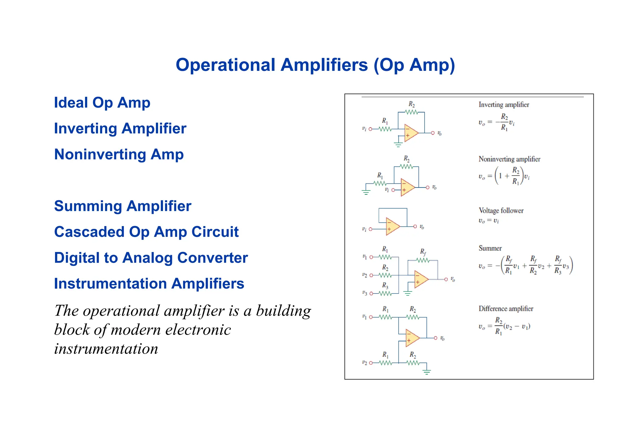
Operational Amplifiers (OpAmp)
Ideal Op Amp
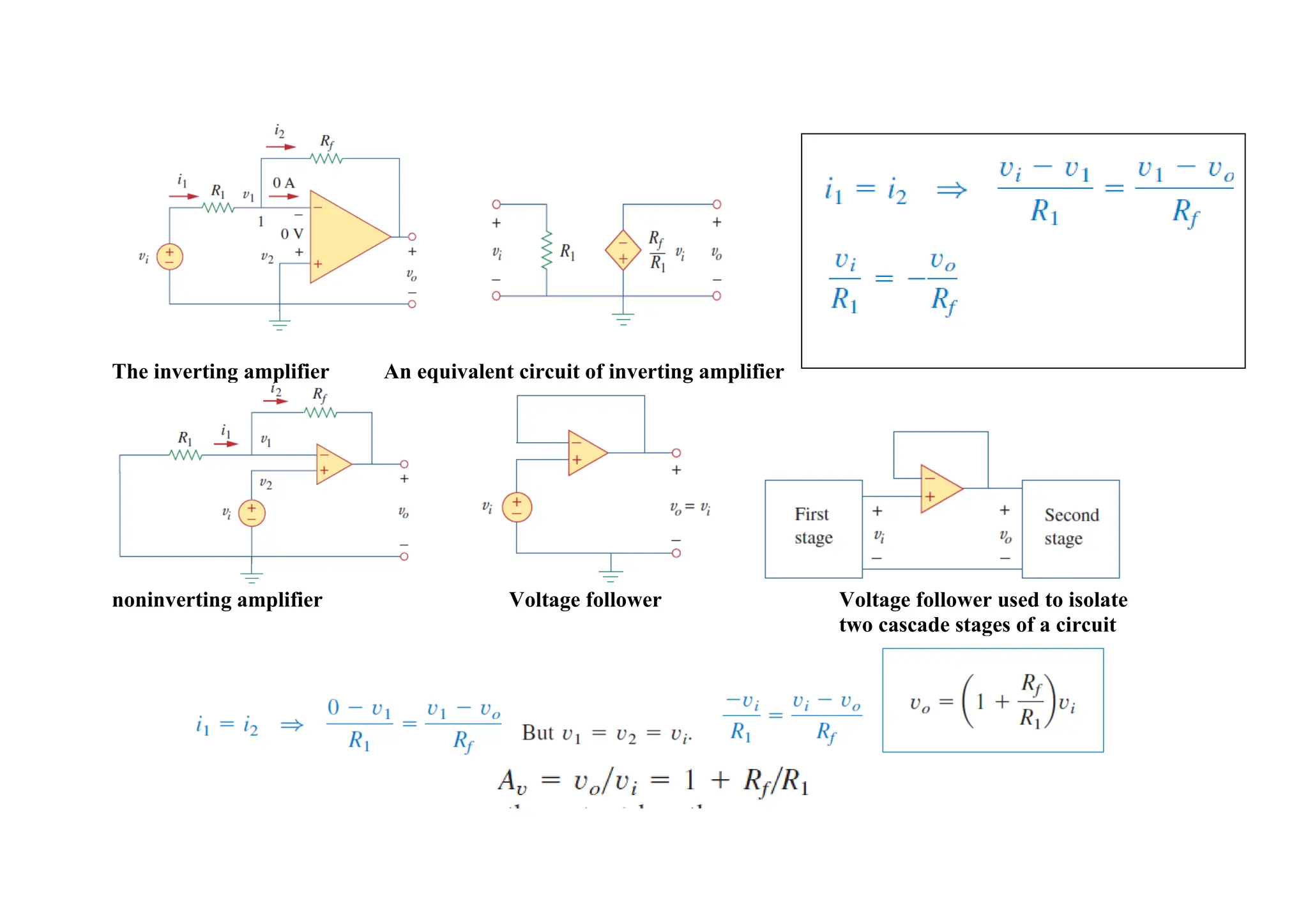
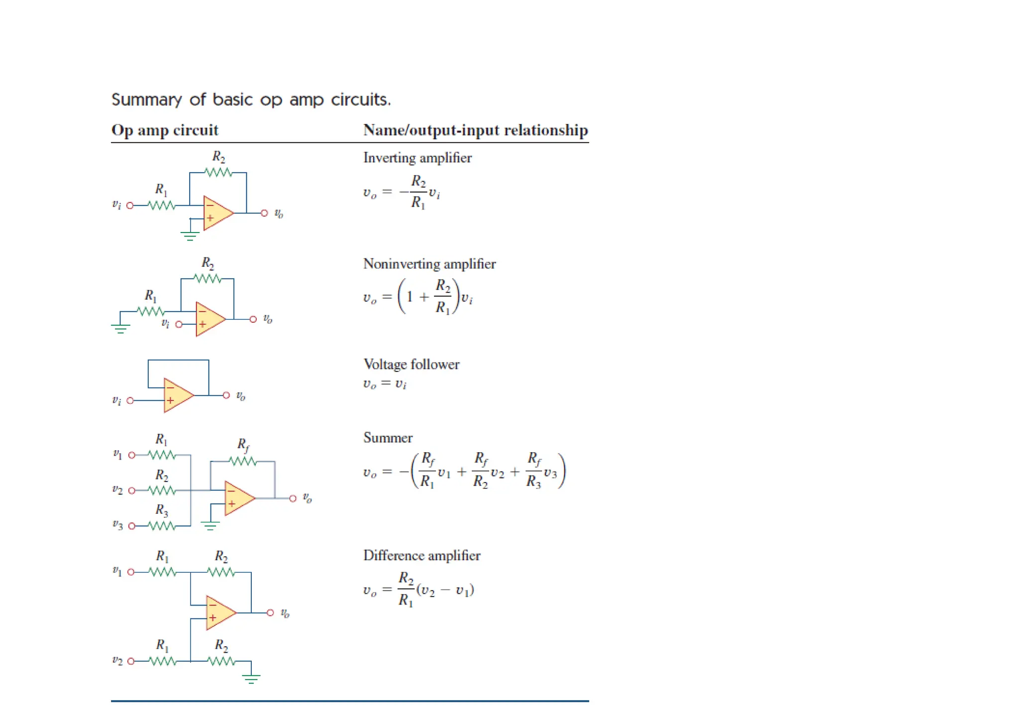
Inverting Amplifier
Noninverting Amp
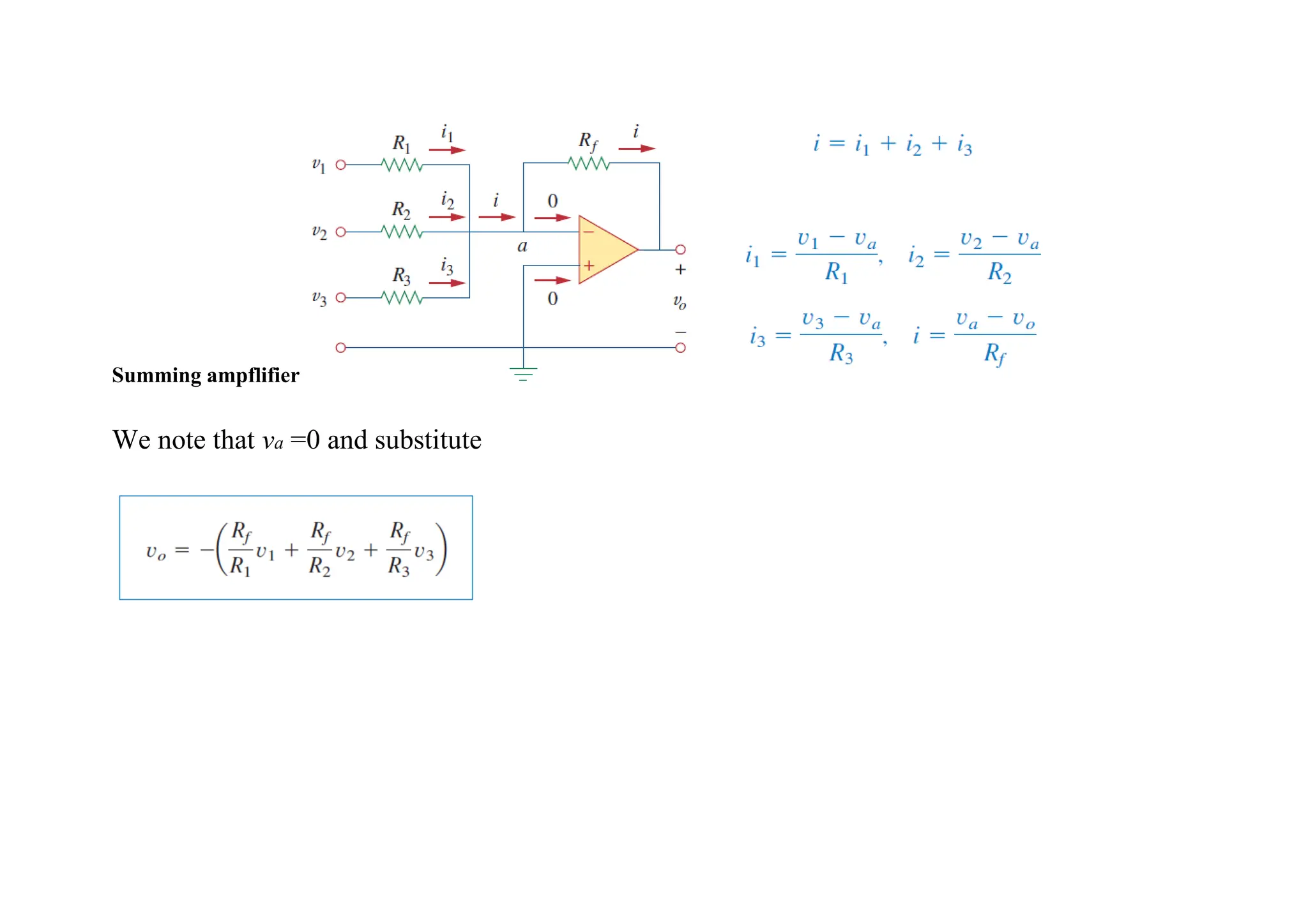
Summing Amplifier
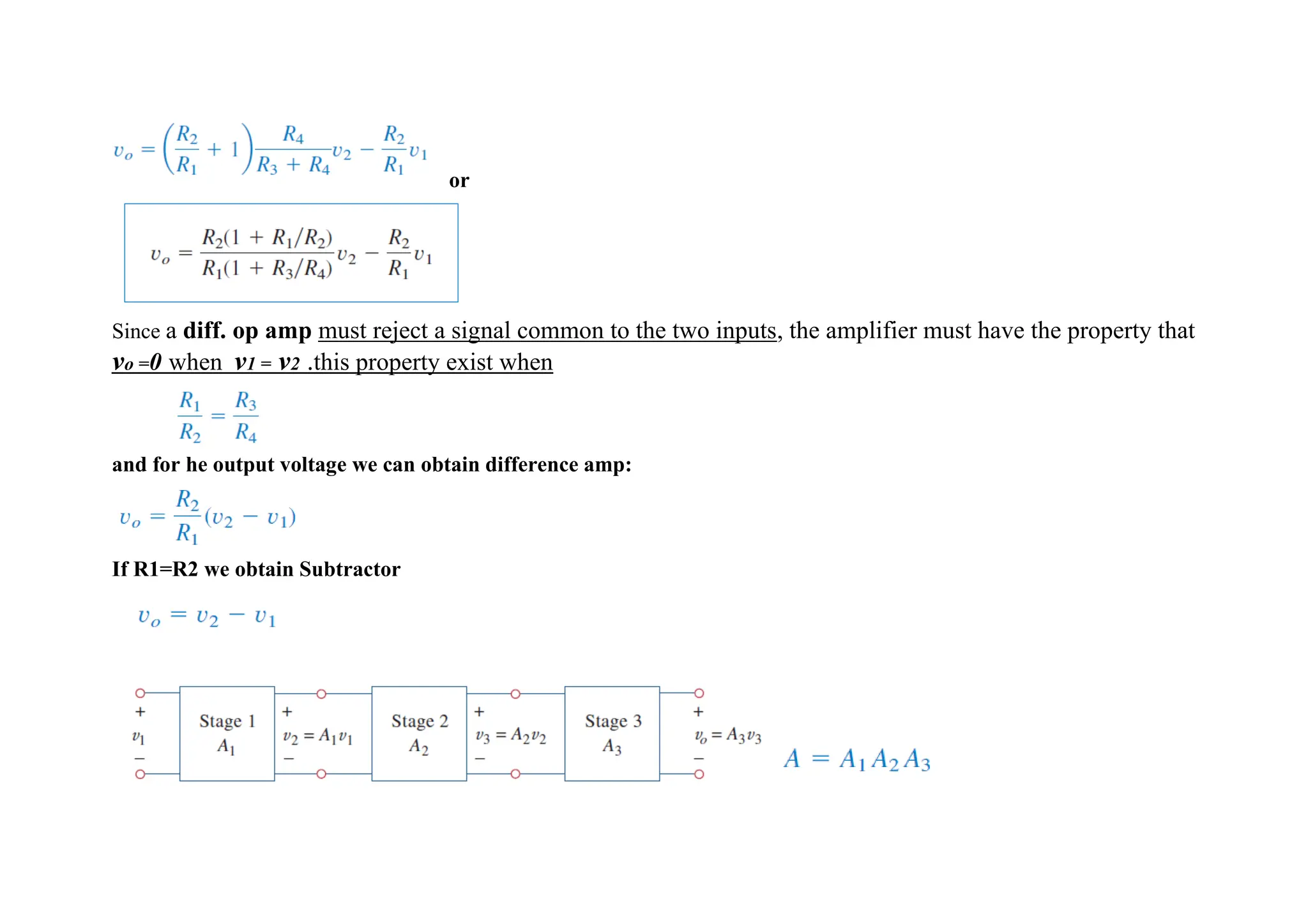
Cascaded Op Amp Circuit
Digital to Analog Converter
Instrumentation Amplifiers
The operational amplifier is a building
block of modern electronic
instrumentation
2.
Engineering applyphysical principles to design devices for the
humanity.
physical principles cannot be understood without measurement.
physics is the science that measures reality.
measurements are a tool for understanding the physical world
instruments are tools for measurement.
operational amplifier fundamentals = practical application of electronic
circuits.
Electronic instruments are used in all fields of science and engineering.
physicists, physiologists, and biologists must learn to use el. instruments.
students: the skill in operating digital and analog el. instruments is crucial.
Such instruments include ammeters, voltmeters, ohmmeters,
oscilloscopes,
electrical engineers specialize in designing and constructing electronic
instruments (invent and patent their inventions)
Specialists in electronic instruments find employment in medical
schools, hospitals, research laboratories, aircraft industries
3.
Operational Amplifiers
✓The opamp behaves like a voltage-controlled voltage source.
✓An op amp may also be regarded as a voltage amplifier with very high gain.
✓An operational amplifier is designed so that it performs some mathematical
operations when external components, such as resistors and capacitors, are
connected to its terminals.
✓op amp is an active circuit element designed to perform mathematical
operations of addition, subtraction, multiplication, division, differentiation,
and integration.
✓The op amp is an electronic device consisting of a complex arrangement of
resistors, transistors, capacitors, and diodes.
✓A full discussion of what is inside the op amp is beyond the scope of this
course. It will suffice to treat the op amp as a circuit building block and
simply study what takes place at its terminals.
✓Op amps are commercially available in integrated circuit packages in several
forms.
4.
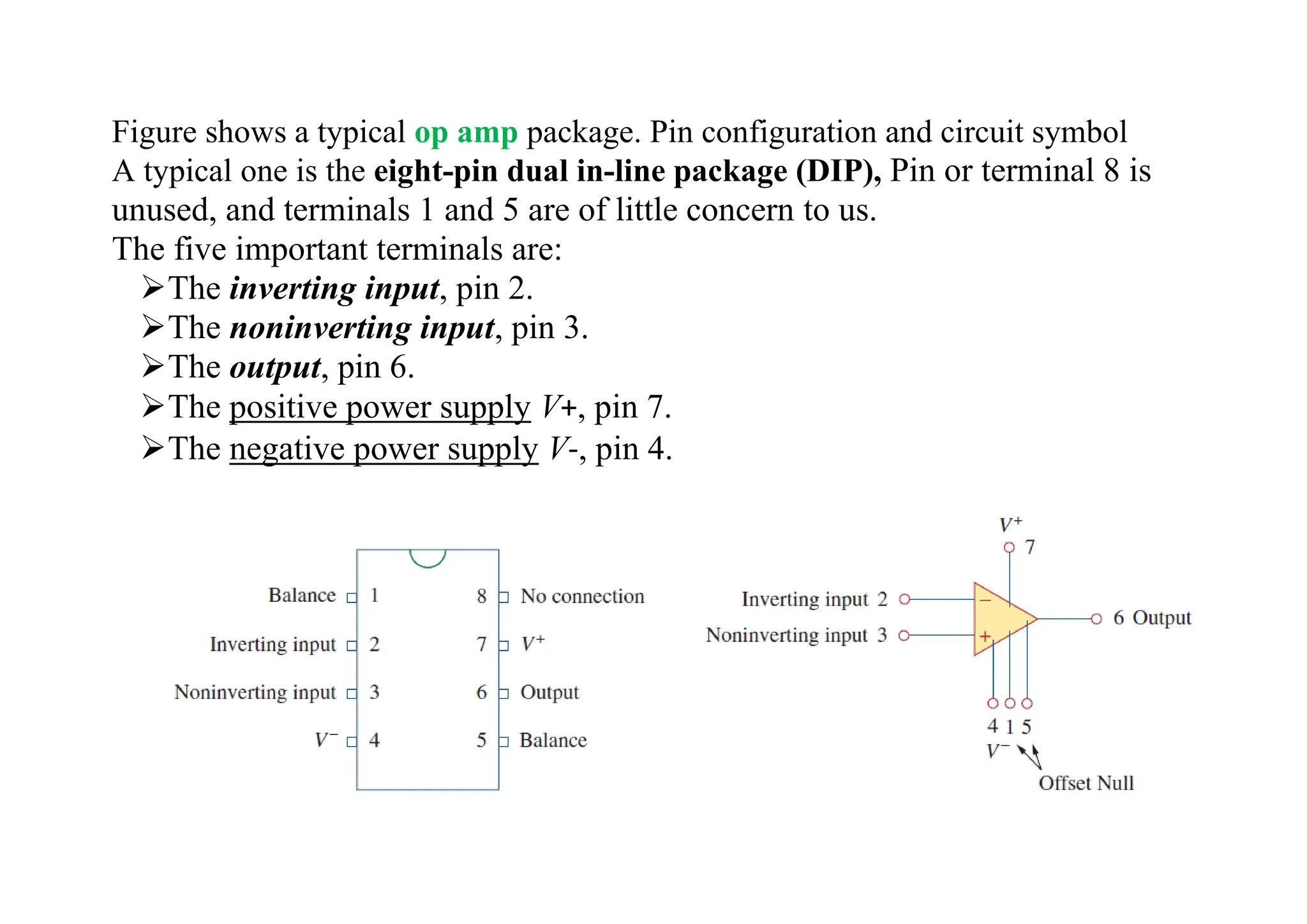
Figure shows atypical op amp package. Pin configuration and circuit symbol
A typical one is the eight-pin dual in-line package (DIP), Pin or terminal 8 is
unused, and terminals 1 and 5 are of little concern to us.
The five important terminals are:
➢The inverting input, pin 2.
➢The noninverting input, pin 3.
➢The output, pin 6.
➢The positive power supply V+, pin 7.
➢The negative power supply V-, pin 4.
5.
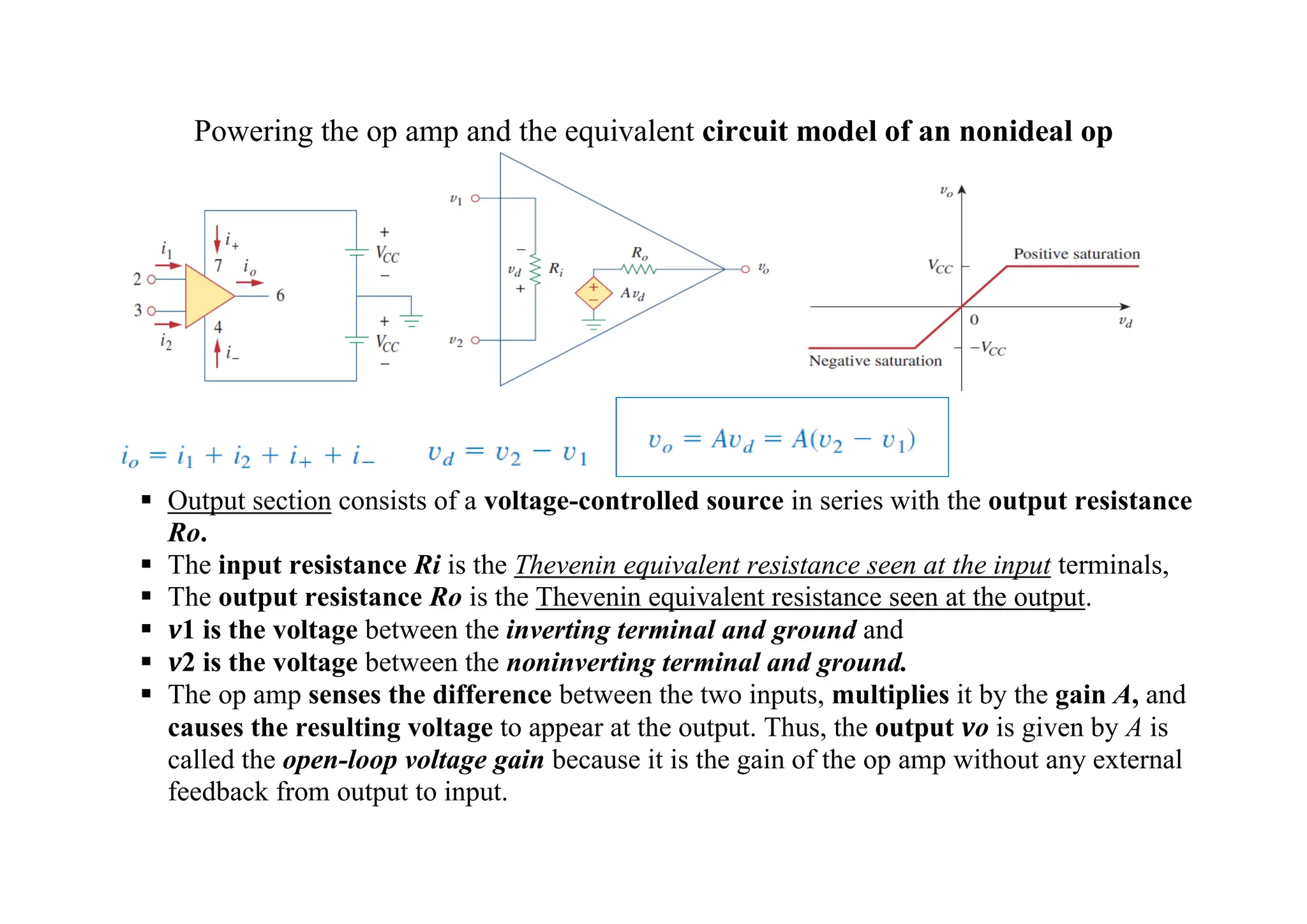
Powering the opamp and the equivalent circuit model of an nonideal op
▪ Output section consists of a voltage-controlled source in series with the output resistance
Ro.
▪ The input resistance Ri is the Thevenin equivalent resistance seen at the input terminals,
▪ The output resistance Ro is the Thevenin equivalent resistance seen at the output.
▪ v1 is the voltage between the inverting terminal and ground and
▪ v2 is the voltage between the noninverting terminal and ground.
▪ The op amp senses the difference between the two inputs, multiplies it by the gain A, and
causes the resulting voltage to appear at the output. Thus, the output vo is given by A is
called the open-loop voltage gain because it is the gain of the op amp without any external
feedback from output to input.
6.
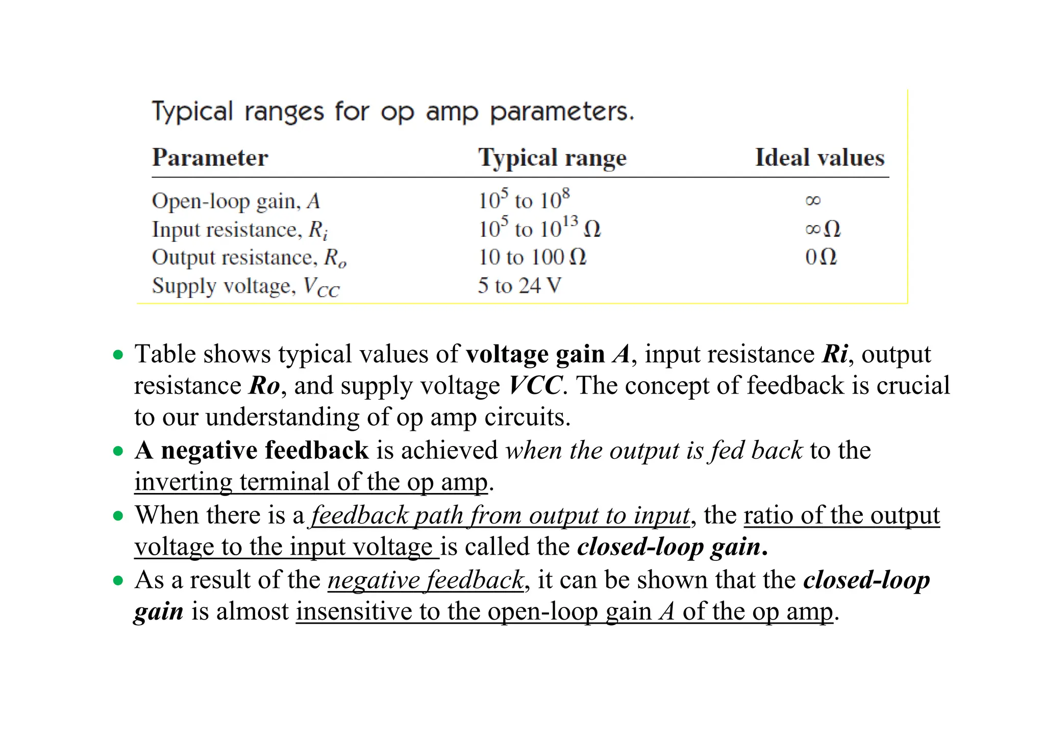
• Table showstypical values of voltage gain A, input resistance Ri, output
resistance Ro, and supply voltage VCC. The concept of feedback is crucial
to our understanding of op amp circuits.
• A negative feedback is achieved when the output is fed back to the
inverting terminal of the op amp.
• When there is a feedback path from output to input, the ratio of the output
voltage to the input voltage is called the closed-loop gain.
• As a result of the negative feedback, it can be shown that the closed-loop
gain is almost insensitive to the open-loop gain A of the op amp.
7.
• For thisreason, op amps are used in circuits with feedback paths. A
practical limitation of the op amp is that the magnitude of its output
voltage cannot exceed |VCC|. In other words, the output voltage is
dependent on and is limited by the power supply voltage
Op amp can operate in three modes, depending on the differential input
voltage vd:
If we attempt to increase vd beyond the linear range, the op amp becomes
saturated and yields vo =+VCC or vo =-VCC.
we will assume that our op amps operate in the linear mode. This means that
the output voltage is restricted by
8.
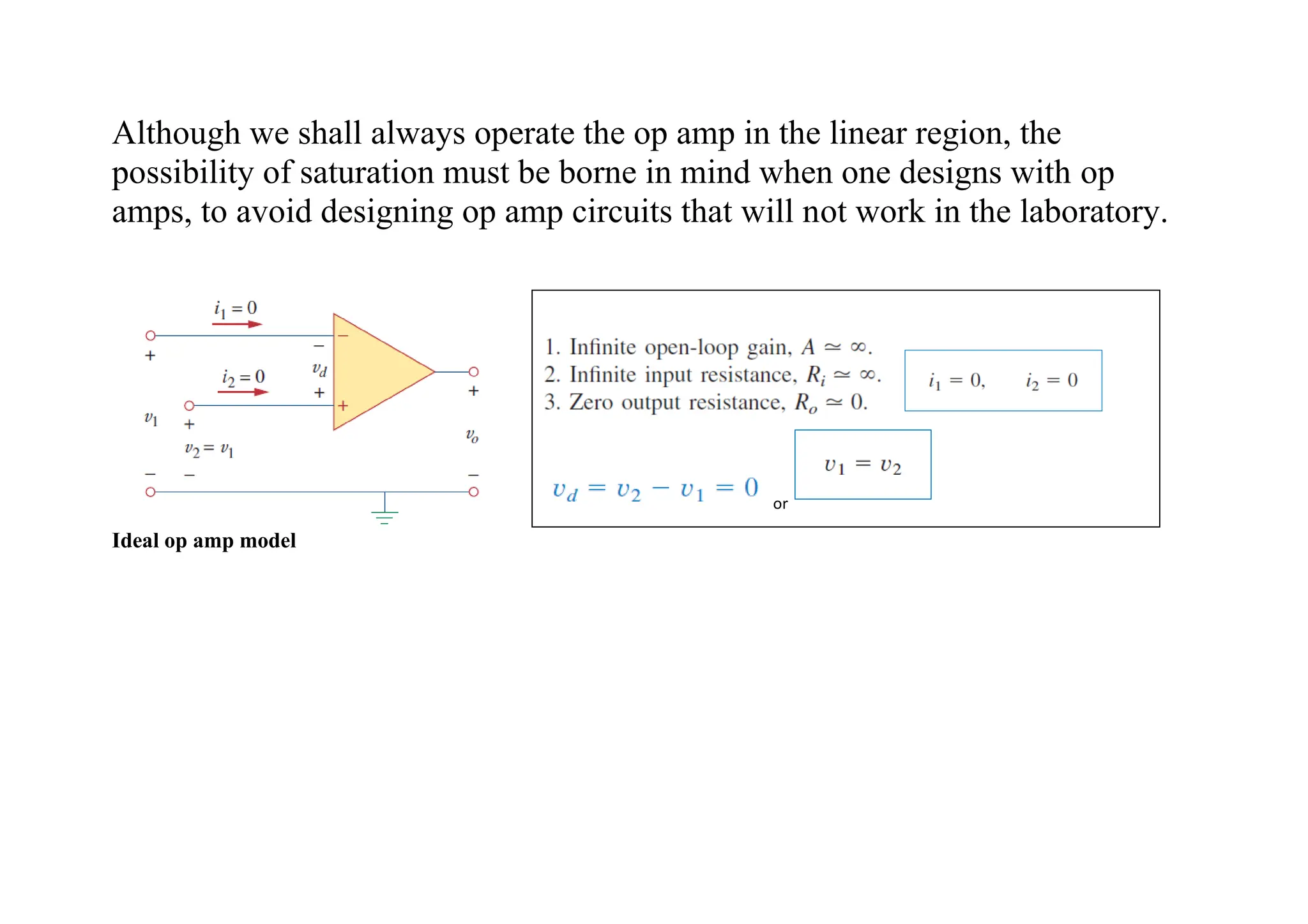
Although we shallalways operate the op amp in the linear region, the
possibility of saturation must be borne in mind when one designs with op
amps, to avoid designing op amp circuits that will not work in the laboratory.
Ideal op amp model
or
9.
The inverting amplifierAn equivalent circuit of inverting amplifier
noninverting amplifier Voltage follower Voltage follower used to isolate
two cascade stages of a circuit
10.
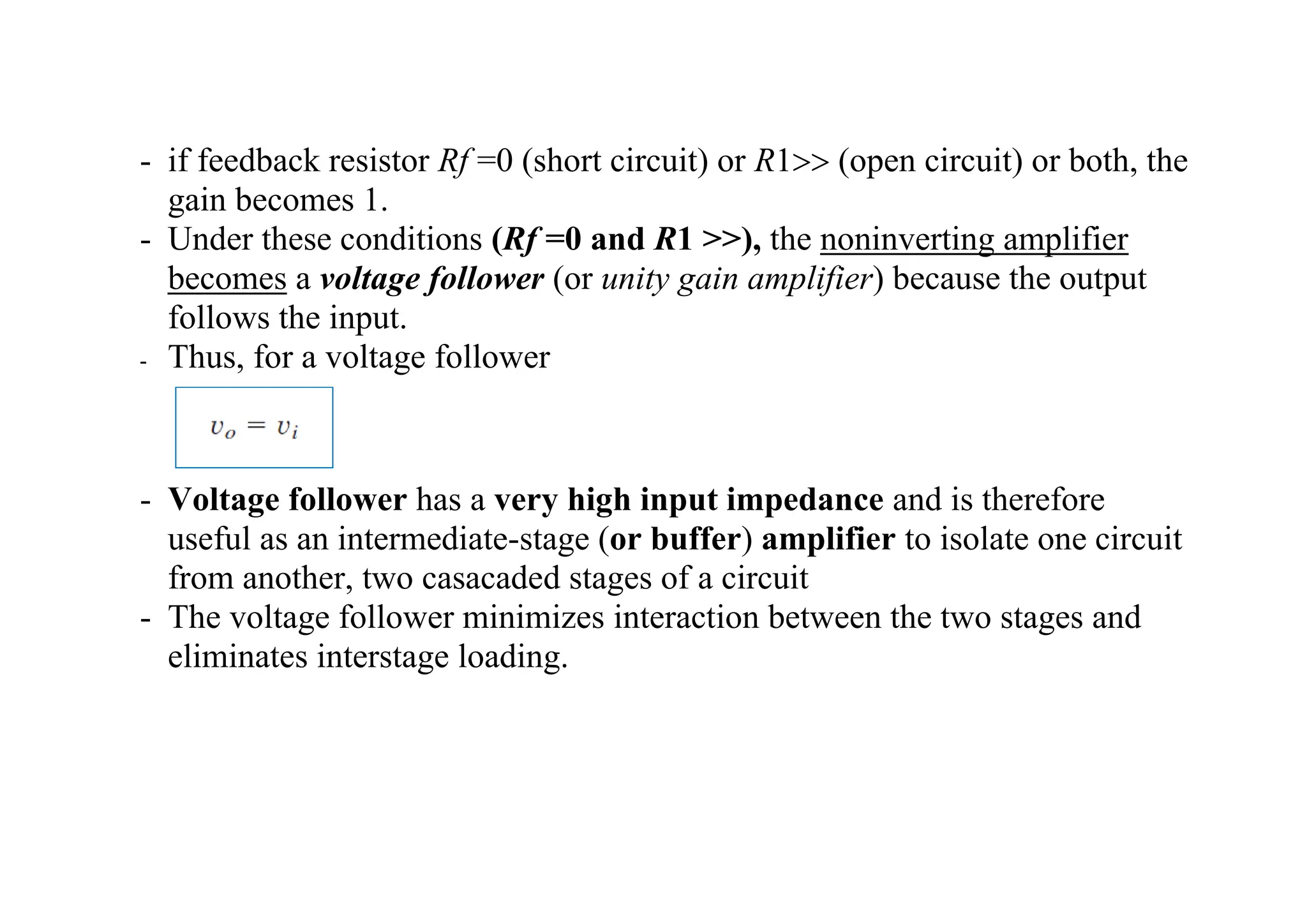
- if feedbackresistor Rf =0 (short circuit) or R1 (open circuit) or both, the
gain becomes 1.
- Under these conditions (Rf =0 and R1 >>), the noninverting amplifier
becomes a voltage follower (or unity gain amplifier) because the output
follows the input.
- Thus, for a voltage follower
- Voltage follower has a very high input impedance and is therefore
useful as an intermediate-stage (or buffer) amplifier to isolate one circuit
from another, two casacaded stages of a circuit
- The voltage follower minimizes interaction between the two stages and
eliminates interstage loading.
or
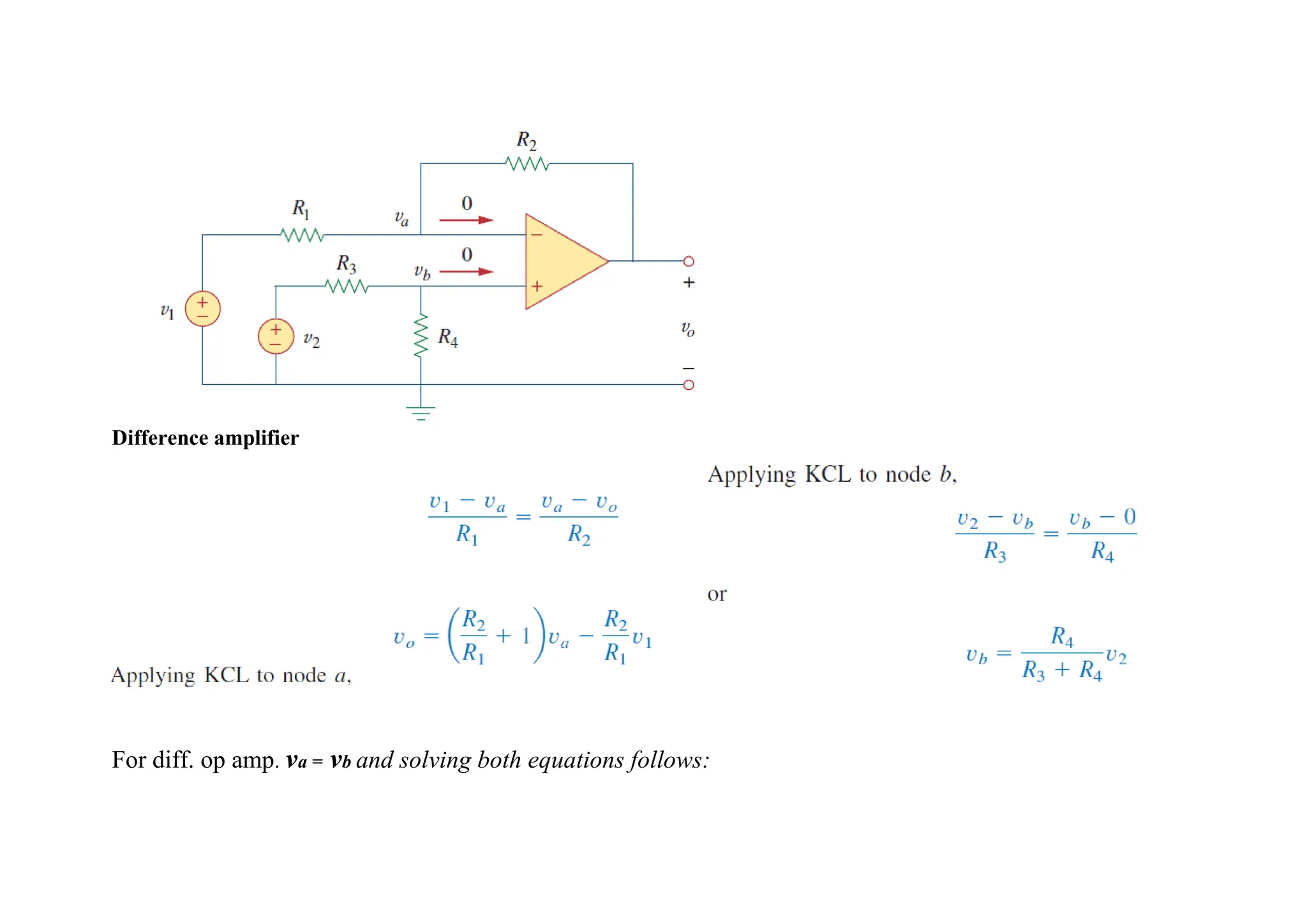
Since a diff.op amp must reject a signal common to the two inputs, the amplifier must have the property that
vo =0 when v1 = v2 .this property exist when
and for he output voltage we can obtain difference amp:
If R1=R2 we obtain Subtractor
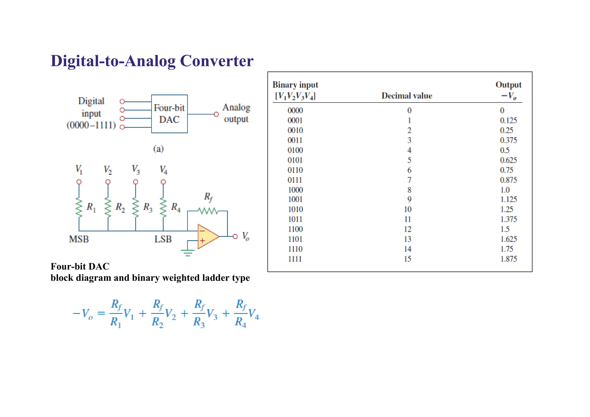
• The digital-to-analogconverter (DAC) transforms digital signals
into analog form.
• The four-bit DAC can be realized in many ways. A simple
realization is the binary weighted ladder.
• The bits are weights according to the magnitude of their place value,
• by descending value of Rf-Rn so that each lesser bit has half the
weight of the next higher.
• This is obviously an inverting summing amplifier.
• The output voltage is related to the inputs as shown in Equation
• Input V1 is called the most significant bit (MSB),
• Input V4 is the least significant bit (LSB).
• Each of the four binary inputs V1, . . . , V4 can assume only two
voltage levels: 0 or 1 V.
• By using the proper input and feedback resistor values, the DAC
provides a single output that is proportional to the inputs.
16.
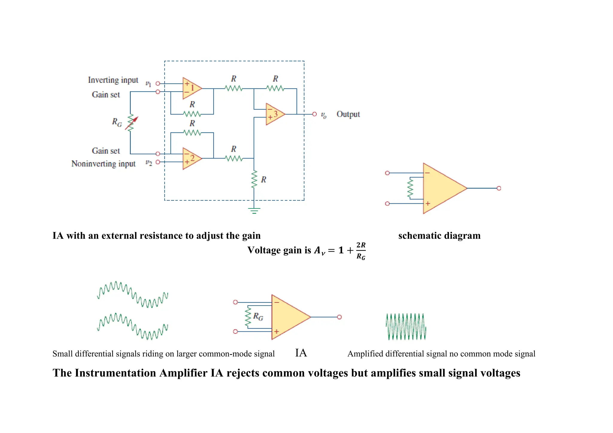
Instrumentation Amplifiers
• Instrumentationamplifier (IA) most useful, flexible and adaptable op
amp circuits for precision measurement and process control.
• Typical applications of IAs include isolation amplifiers, thermocouple
amplifiers, and data acquisition systems.
• The instrumentation amplifier is an extension of the difference amplifier
in that it amplifies the difference between its input signals.
• Instrumentation amplifier typically consists of three op amps and seven
resistors.
• For practical design of IA the resistors are made equal except for the
external gain-setting resistor RG, connected between the gain set
terminals.
•
17.
IA with anexternal resistance to adjust the gain schematic diagram
Voltage gain is 𝑨 = 𝟏 +
𝟐𝑹
𝑹𝑮
Small differential signals riding on larger common-mode signal IA Amplified differential signal no common mode signal
The Instrumentation Amplifier IA rejects common voltages but amplifies small signal voltages
18.
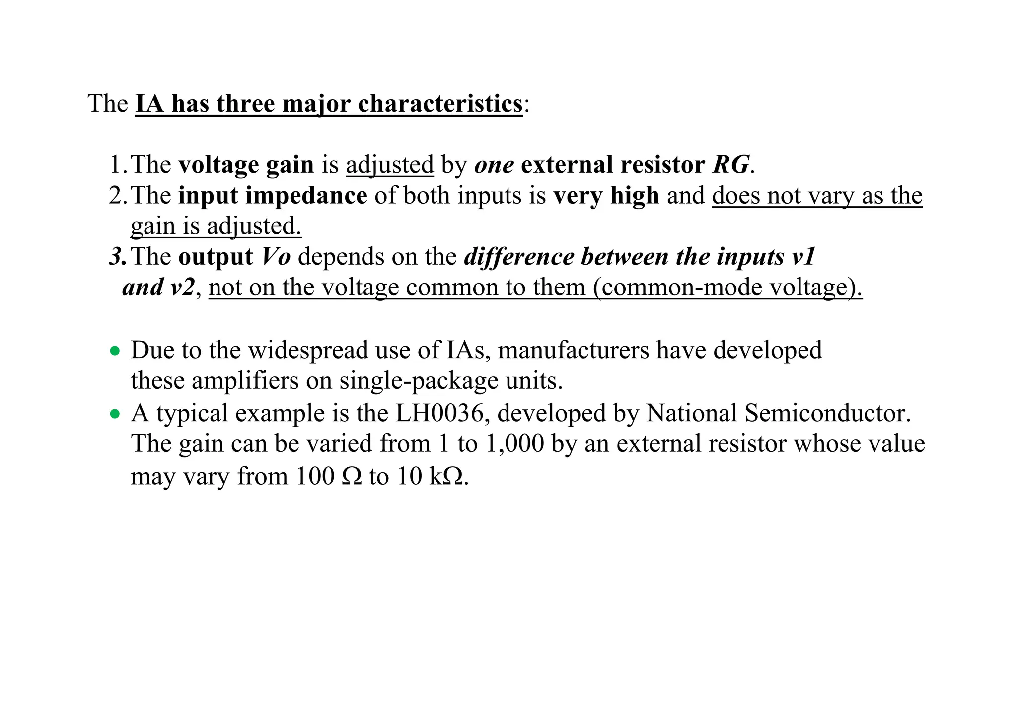
The IA hasthree major characteristics:
1.The voltage gain is adjusted by one external resistor RG.
2.The input impedance of both inputs is very high and does not vary as the
gain is adjusted.
3.The output Vo depends on the difference between the inputs v1
and v2, not on the voltage common to them (common-mode voltage).
• Due to the widespread use of IAs, manufacturers have developed
these amplifiers on single-package units.
• A typical example is the LH0036, developed by National Semiconductor.
The gain can be varied from 1 to 1,000 by an external resistor whose value
may vary from 100 to 10 k.
20.
Summary
• The opamp is a high-gain amplifier that has high input resistance
and low output resistance.
• The expression for the gain of each amplifier circuit holds
whether the inputs are dc, ac, or time-varying in general.
• An ideal op amp has an infinite input resistance, a zero output
resistance, and an infinite gain.
• For an ideal op amp, the current into each of its two input terminals
is zero, and the voltage across its input terminals is negligibly
small.
• In an inverting amplifier, the output voltage is a negative multiple
of the input.
• In a noninverting amplifier, the output is a positive multiple of the
input.
• In a voltage follower, the output follows the input.
• In a summing amplifier, the output is the weighted sum of the
inputs.
21.
• In adifference amplifier, the output is proportional to the difference
of the two inputs.
• Op amp circuits may be cascaded without changing their input- output
relationships.
• PSpice can be used to analyze an op amp circuit.
• Typical applications of the op amp include the digital-to-analog converter
and the instrumentation amplifier.