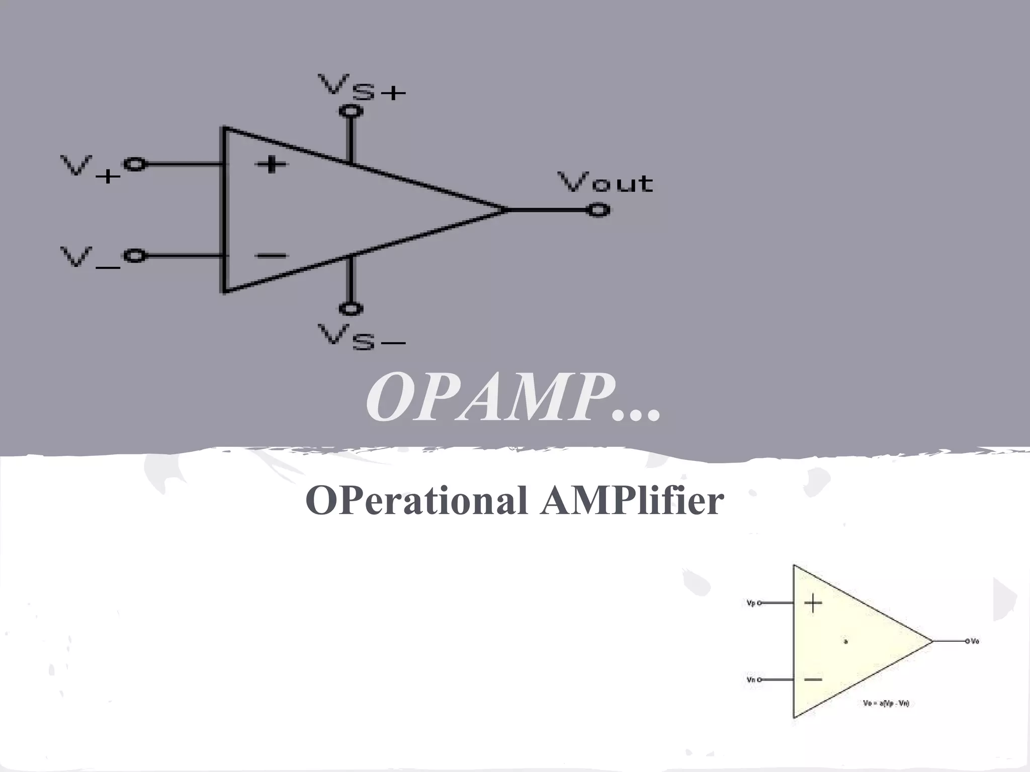
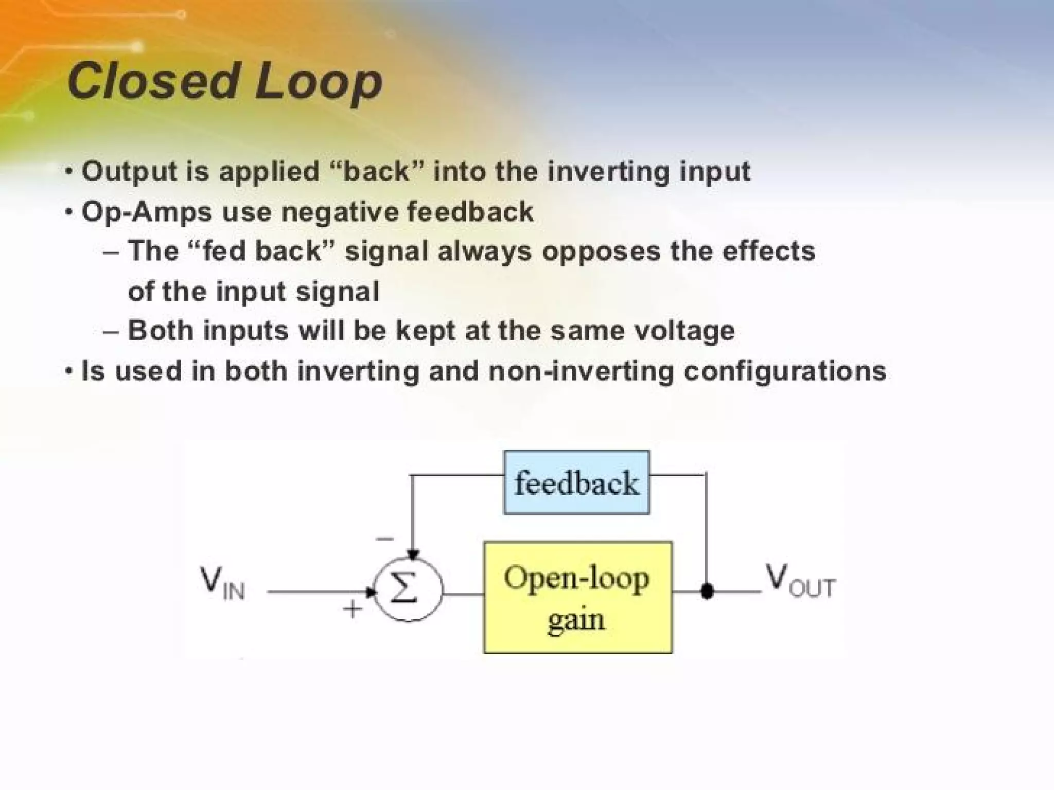
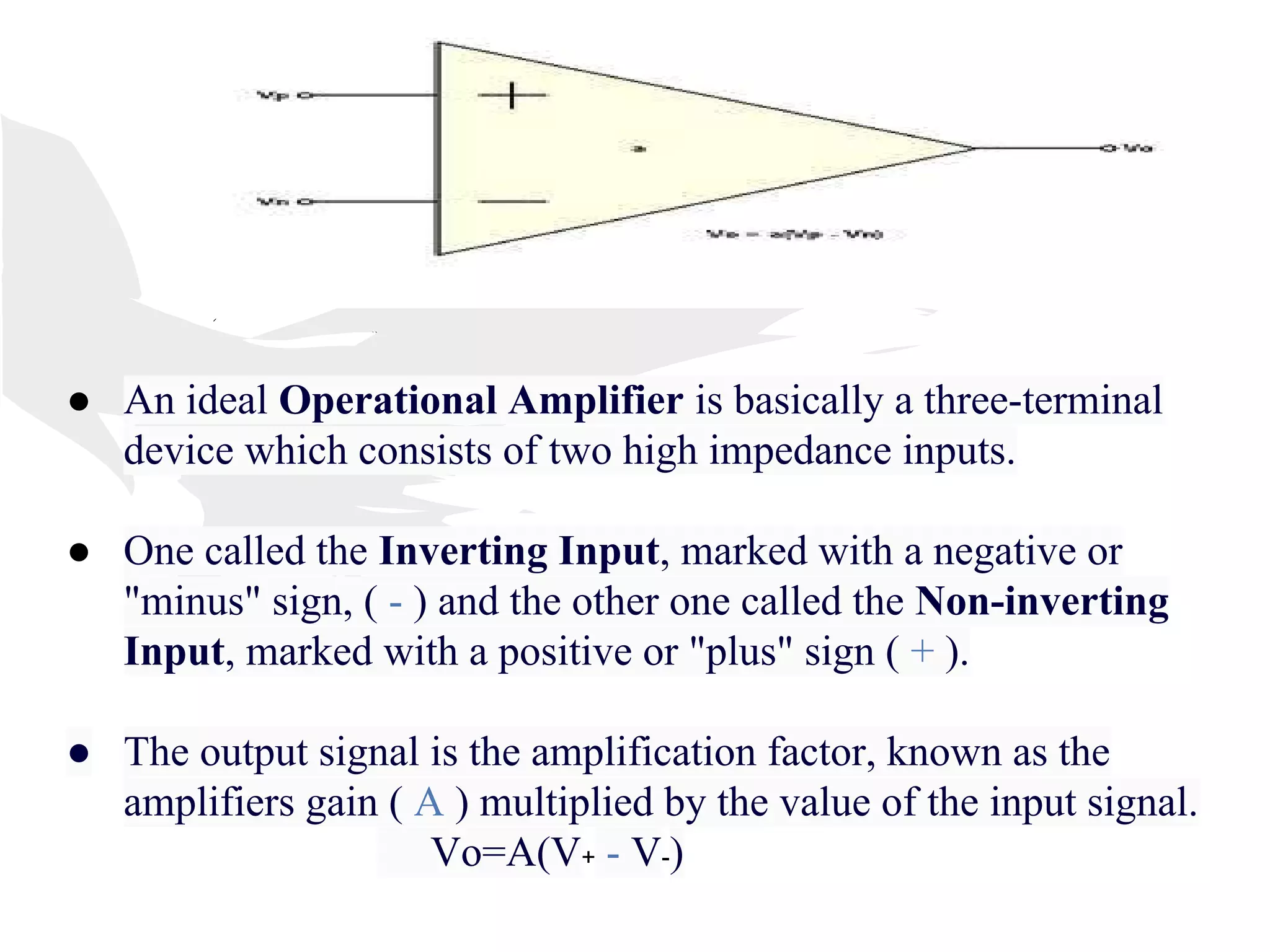
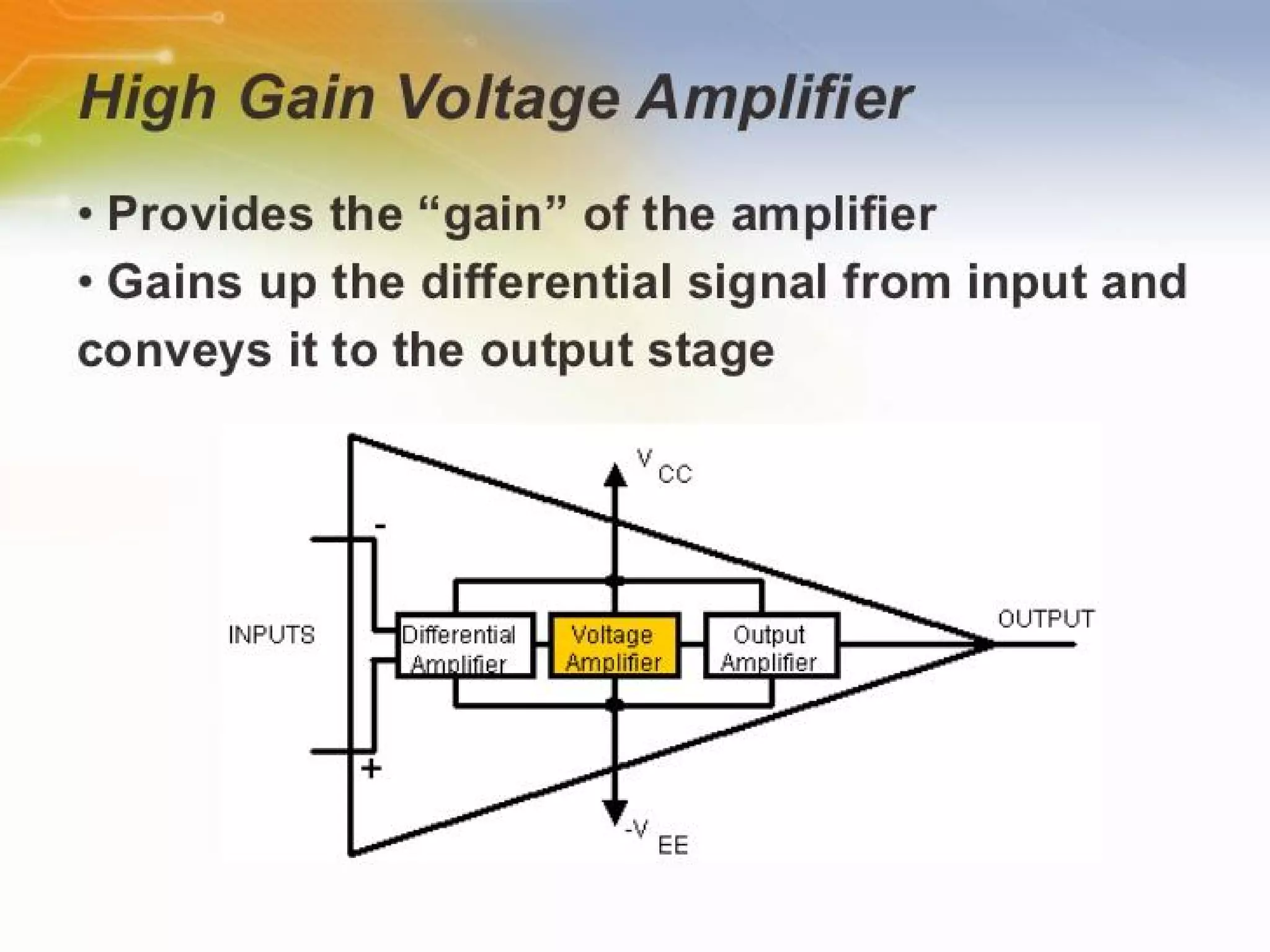
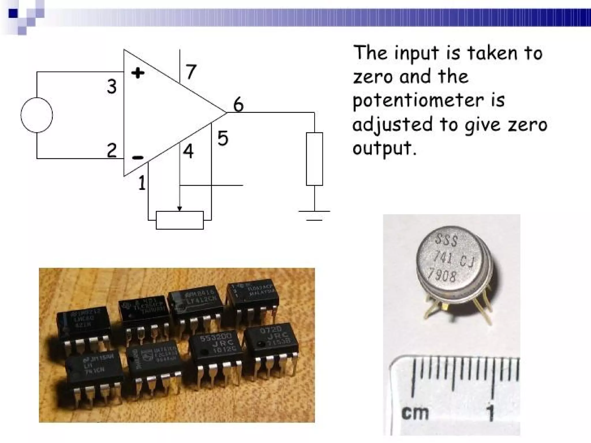
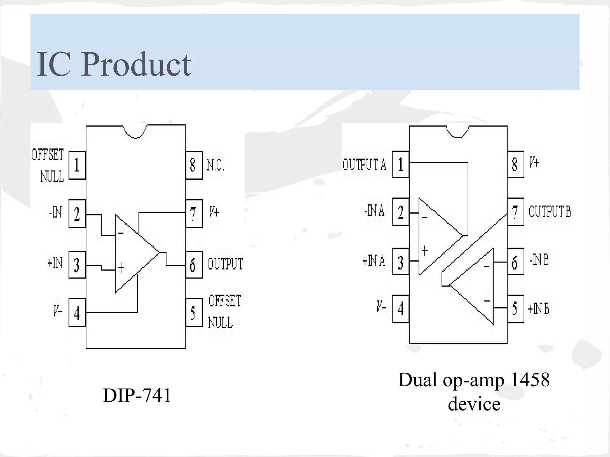
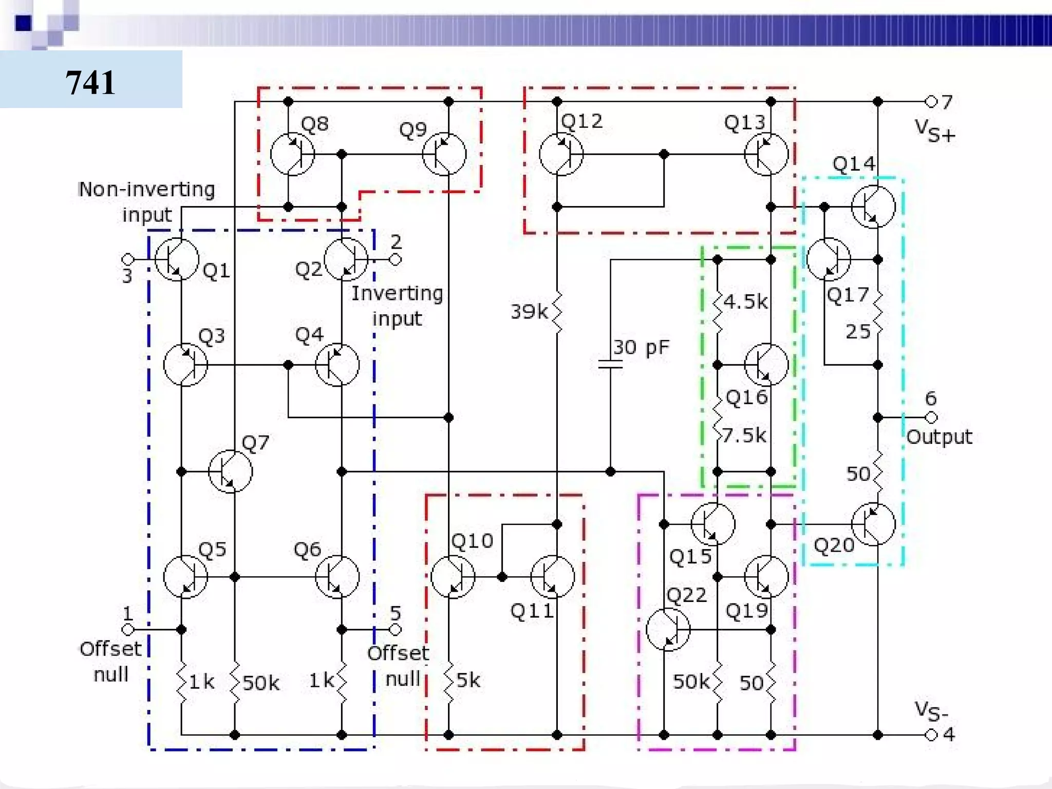
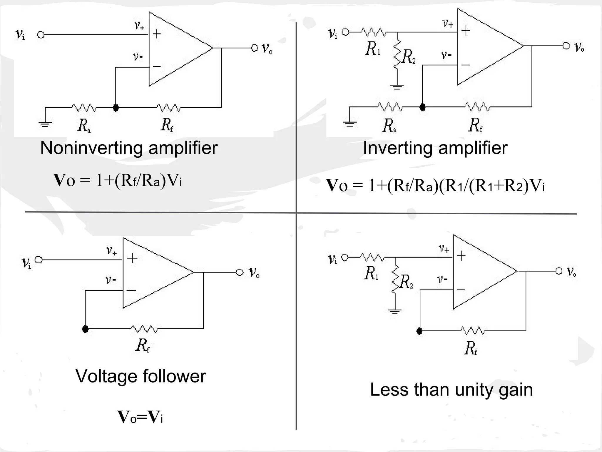
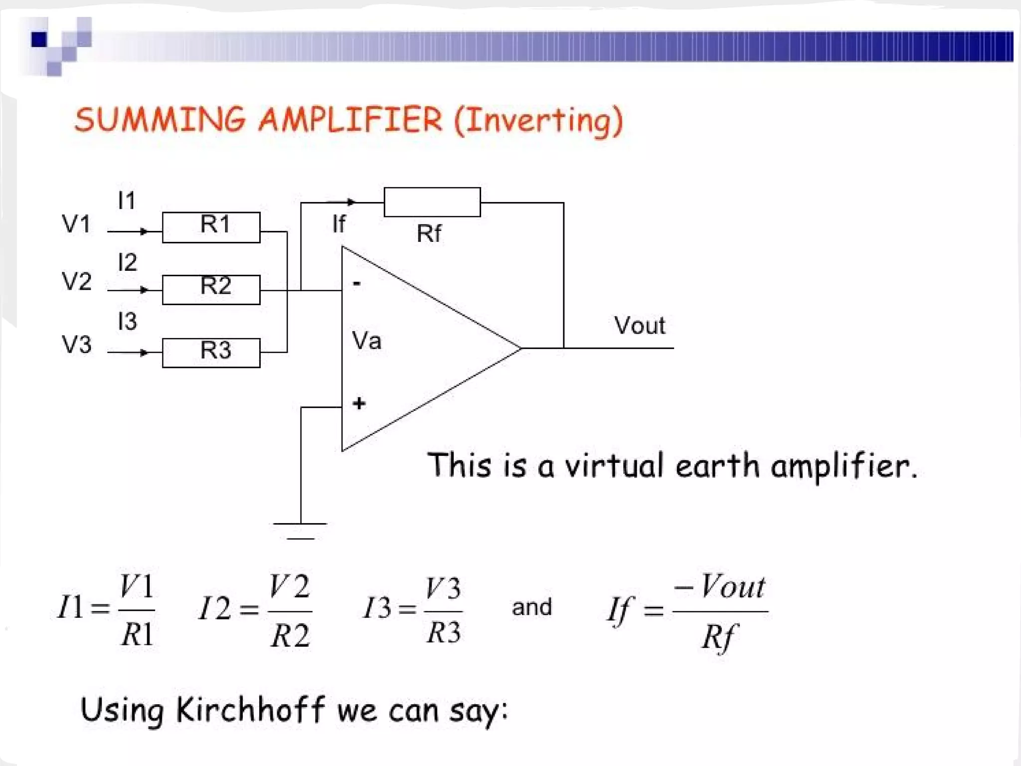
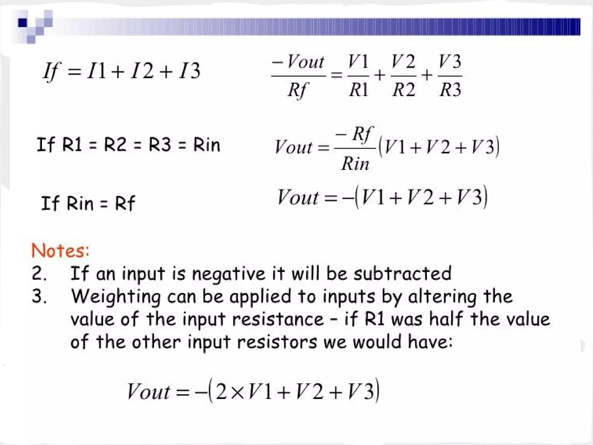
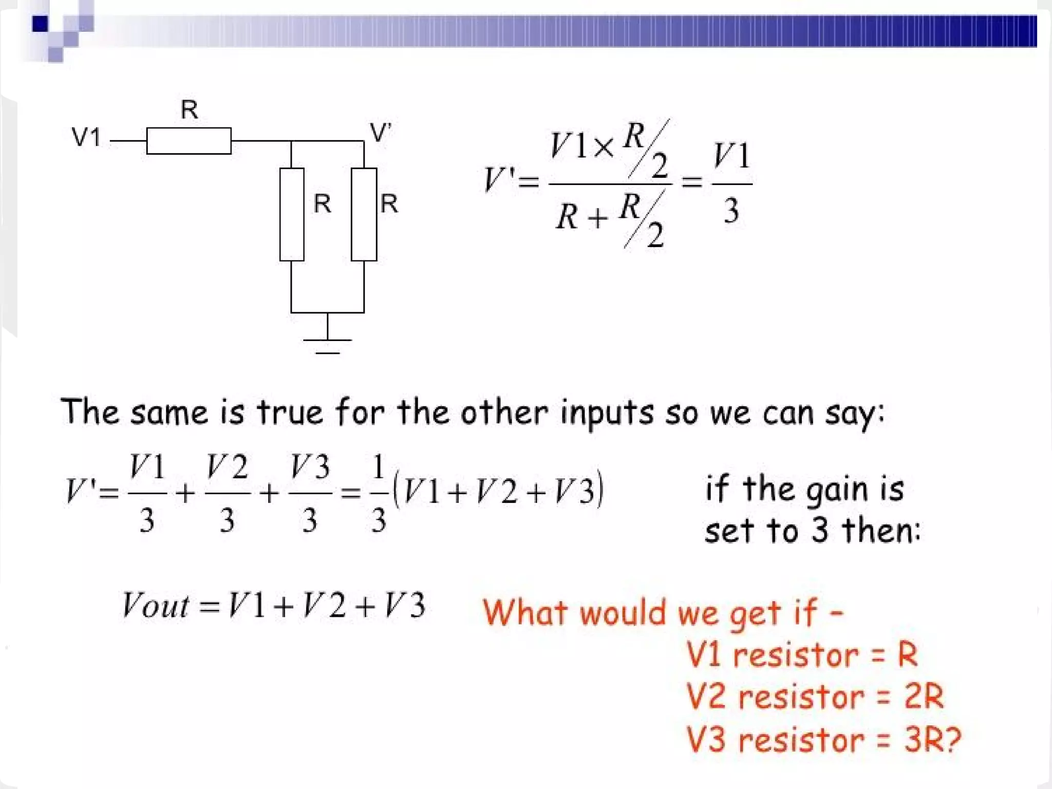
OPAMP...
OPerational AMPlifier
Intro...
● Op-amps are among the most widely used electronic devices
today.
● One of the basic building blocks of Analogue Electronic
Circuits.
● A DC-coupled high-gain electronic voltage amplifier.
● Has a differential input and, usually, a single-ended output.
● High open loop gain, typically it is ~ 10^4-10^5.
● By using negative feedback, we throw most of that away!
● An ideal Operational Amplifier is basically a three-terminal
device which consists of two high impedance inputs.
● One called the Inverting Input, marked with a negative or
"minus" sign, ( - ) and the other one called the Non-inverting
Input, marked with a positive or "plus" sign ( + ).
● The output signal is the amplification factor, known as the
amplifiers gain ( A ) multiplied by the value of the input signal.
Vo=A(V+ - V-)
➔ A generalized form of a differential amplifier:
● V1,V2: Inputs
● The two identical transistors TR1
and TR2 are both biased at the same
operating point with their emitters
connected together and returned to
the common rail, -Vee by way of
resistor Re.
● The circuit operates from a dual
supply+Vcc and -Vee which
ensures a constant supply.
● Vout=V1-V2
Equivalent Circuit for Ideal Operational Amplifiers:
-
● V1 : Inverting input
● V2: Inverting input
● A: Gain
● Vdiff: V1-V2
● +Vsupply: +ve power supply
● -Vsupply: -ve power supply
Properties of ideal op amp...
● Infinite open-loop gain
● Infinite voltage range available at the output
● Infinite bandwidth with zero phase shift and infinite slew
rate
● Infinite input impedance. So zero input current and zero
input offset voltage
● Zero output impedance
● Zero noise
● Infinite Common-mode rejection ratio (CMRR)
Common-Mode Operation
● Same voltage source is applied at
both terminals
● Ideally, two input are equally amplified
● Output voltage is ideally zero due to differential voltage is
zero
● Practically, a small output signal can still be measured
● Note for differential circuits:
○ Opposite inputs : highly amplified
○ Common inputs : slightly amplified
Common-Mode Rejection
Single-Ended Input
● + terminal : Ground
● – terminal : Source
● 180o
phase change
● + terminal : Source
● – terminal : Ground
● 0o
phase change
Ideal Practical
Open Loop gain A µ
10
5
Bandwidth BW µ 0-100Hz
Input Impedance
Z
in
µ >1MW
Output Impedance
Z
out
0 W 10-100 W
Output Voltage
Vout
Depends only on V
d
=
(V
+
-V
-
)
Differential mode signal
Depends slightly on
average input V
c
=
(V
+
+V
-
)/2 Common-
Mode signal
CMRR µ 10-100dB
IDEAL
v/s
PRAC
TICAL
IC Product
DIP-741
Dual op-amp 1458
device
741
Applications
•Non Inverting Amplifier
•Inverting Amplifier
•Adder (Summing amp)
–(and Subtractor using an Inverter)
•Differential Amplifier
•Integrator
•Differentiator
Noninverting amplifier Inverting amplifier
Voltage follower
Less than unity gain
Vo=Vi
Vo = 1+(Rf/Ra)Vi Vo = 1+(Rf/Ra)(R1/(R1+R2)Vi
Differential amplifier
Basics of op amp
Basics of op amp
Basics of op amp
Basics of op amp
Basics of op amp
Basics of op amp
Basics of op amp

Basics of op amp

  • 1.
  • 2.
    Intro... ● Op-amps areamong the most widely used electronic devices today. ● One of the basic building blocks of Analogue Electronic Circuits. ● A DC-coupled high-gain electronic voltage amplifier. ● Has a differential input and, usually, a single-ended output. ● High open loop gain, typically it is ~ 10^4-10^5. ● By using negative feedback, we throw most of that away!
  • 6.
    ● An idealOperational Amplifier is basically a three-terminal device which consists of two high impedance inputs. ● One called the Inverting Input, marked with a negative or "minus" sign, ( - ) and the other one called the Non-inverting Input, marked with a positive or "plus" sign ( + ). ● The output signal is the amplification factor, known as the amplifiers gain ( A ) multiplied by the value of the input signal. Vo=A(V+ - V-)
  • 7.
    ➔ A generalizedform of a differential amplifier: ● V1,V2: Inputs ● The two identical transistors TR1 and TR2 are both biased at the same operating point with their emitters connected together and returned to the common rail, -Vee by way of resistor Re. ● The circuit operates from a dual supply+Vcc and -Vee which ensures a constant supply. ● Vout=V1-V2 Equivalent Circuit for Ideal Operational Amplifiers: - ● V1 : Inverting input ● V2: Inverting input ● A: Gain ● Vdiff: V1-V2 ● +Vsupply: +ve power supply ● -Vsupply: -ve power supply
  • 13.
    Properties of idealop amp... ● Infinite open-loop gain ● Infinite voltage range available at the output ● Infinite bandwidth with zero phase shift and infinite slew rate ● Infinite input impedance. So zero input current and zero input offset voltage ● Zero output impedance ● Zero noise ● Infinite Common-mode rejection ratio (CMRR)
  • 14.
    Common-Mode Operation ● Samevoltage source is applied at both terminals ● Ideally, two input are equally amplified ● Output voltage is ideally zero due to differential voltage is zero ● Practically, a small output signal can still be measured ● Note for differential circuits: ○ Opposite inputs : highly amplified ○ Common inputs : slightly amplified Common-Mode Rejection
  • 16.
    Single-Ended Input ● +terminal : Ground ● – terminal : Source ● 180o phase change ● + terminal : Source ● – terminal : Ground ● 0o phase change
  • 17.
    Ideal Practical Open Loopgain A µ 10 5 Bandwidth BW µ 0-100Hz Input Impedance Z in µ >1MW Output Impedance Z out 0 W 10-100 W Output Voltage Vout Depends only on V d = (V + -V - ) Differential mode signal Depends slightly on average input V c = (V + +V - )/2 Common- Mode signal CMRR µ 10-100dB IDEAL v/s PRAC TICAL
  • 20.
  • 21.
  • 22.
    Applications •Non Inverting Amplifier •InvertingAmplifier •Adder (Summing amp) –(and Subtractor using an Inverter) •Differential Amplifier •Integrator •Differentiator
  • 23.
    Noninverting amplifier Invertingamplifier Voltage follower Less than unity gain Vo=Vi Vo = 1+(Rf/Ra)Vi Vo = 1+(Rf/Ra)(R1/(R1+R2)Vi
  • 31.