Download to read offline

![Page 10
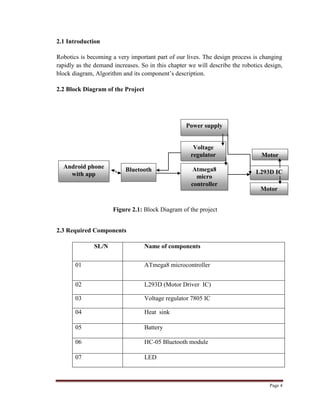
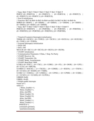
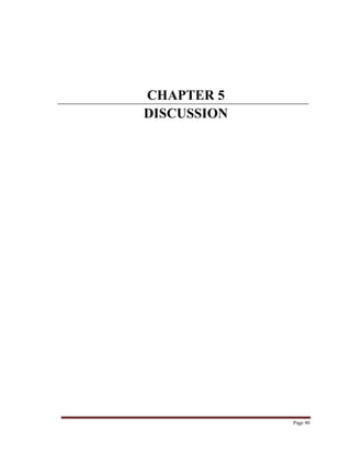
2.6.2 Working of L293D
Here 4 input pins for this l293d, pin 2, 7 on the left and pin 15, 10 on the right as shown
on the pin diagram. Left input pins will regulate the rotation of motor connected across
left side and right input for motor on the right hand side. The motors are rotated on the
basis of the inputs provided across the input pins as LOGIC 0 or LOGIC 1.In simple we
need to provide Logic 0 or 1 across the input pins for rotating the motor.
2.6.3 L293D Logic Table
Let‟s consider a Motor connected on left side output pins (pin 3, 6). For rotating
the motor in clockwise direction the input pins has to be provided with Logic 1 and Logic
0.
• Pin 2 = Logic 1 and Pin 7 = Logic 0 | Clockwise Direction
• Pin 2 = Logic 0 and Pin 7 = Logic 1 | Anticlockwise Direction
• Pin 2 = Logic 0 and Pin 7 = Logic 0 | Idle [No rotation] [Hi-Impedance state]
• Pin 2 = Logic 1 and Pin 7 = Logic 1 | Idle [No rotation]
In a very similar way the motor can also operated across input pin 15, 10 for motor on the
right hand side.
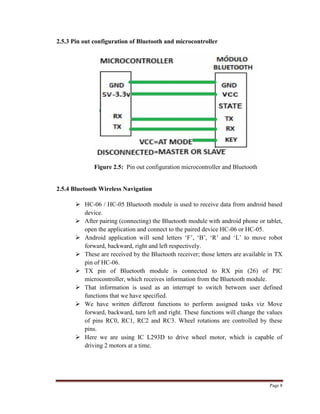
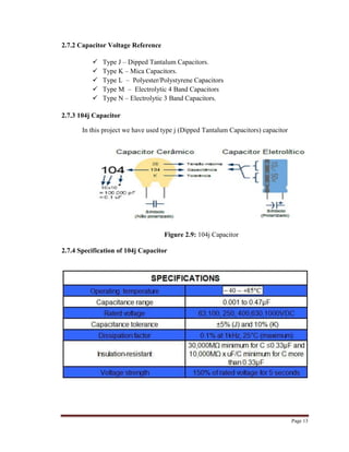
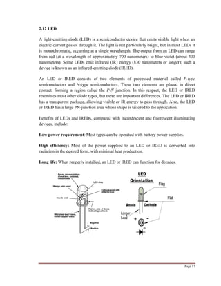
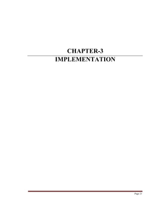
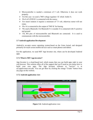
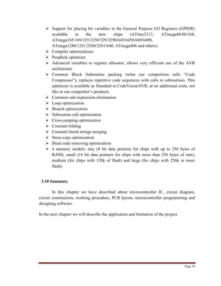
2.6.4 Circuit Diagram of L293D motor driver IC controller
Figure: 2.7: Circuit Diagram of L293D](https://image.slidesharecdn.com/part2master-150818134755-lva1-app6891/85/Part-2-master-10-320.jpg)
![Page 25
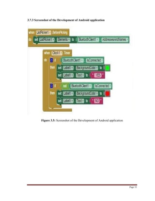
#define Motor_B_PORT1 PORTB.4
#define Motor_B_PORT2 PORTB.5
#define Motor_Enable1 PORTB.1
#define Motor_Enable2 PORTB.2
// Declare your global variables here
#define DATA_REGISTER_EMPTY (1<<UDRE)
#define RX_COMPLETE (1<<RXC)
#define FRAMING_ERROR (1<<FE)
#define PARITY_ERROR (1<<UPE)
#define DATA_OVERRUN (1<<DOR)
// USART Receiver buffer
#define RX_BUFFER_SIZE 8
char rx_buffer [RX_BUFFER_SIZE];
#if RX_BUFFER_SIZE <= 256
unsigned char rx_wr_index=0, rx_rd_index=0;
#else
unsigned int rx_wr_index=0, rx_rd_index=0;
#endif
#if RX_BUFFER_SIZE < 256
unsigned char rx_counter = 0;
#else
unsigned int rx_counter=0;
#endif
// This flag is set on USART Receiver buffer overflow
bit rx_buffer_overflow;
// USART Receiver interrupt service routine
interrupt [USART_RXC] void usart_rx_isr (void)
{
char status,data;
status=UCSRA;
data=UDR;
if ((status & (FRAMING_ERROR | PARITY_ERROR | DATA_OVERRUN))==0)
{
rx_buffer[rx_wr_index++]=data;
#if RX_BUFFER_SIZE == 256
// special case for receiver buffer size=256
if (++rx_counter == 0) rx_buffer_overflow=1;
#else
if (rx_wr_index == RX_BUFFER_SIZE) rx_wr_index=0;
if (++rx_counter == RX_BUFFER_SIZE)
{](https://image.slidesharecdn.com/part2master-150818134755-lva1-app6891/85/Part-2-master-25-320.jpg)
![Page 26
rx_counter=0;
rx_buffer_overflow=1;
}
#endif
}
}
#ifndef _DEBUG_TERMINAL_IO_
// Get a character from the USART Receiver buffer
#define _ALTERNATE_GETCHAR_
#pragma used+
///
char getchar (void)
{
char data;
while (rx_counter==0);
data=rx_buffer[rx_rd_index++];
#if RX_BUFFER_SIZE != 256
if (rx_rd_index == RX_BUFFER_SIZE) rx_rd_index=0;
#endif
#asm("cli")
--rx_counter;
#asm("sei")
return data;
}
#pragma used-
#endif
// USART Transmitter buffer
#define TX_BUFFER_SIZE 8
char tx_buffer[TX_BUFFER_SIZE];
#if TX_BUFFER_SIZE <= 256
unsigned char tx_wr_index=0,tx_rd_index=0;
#else
unsigned int tx_wr_index=0,tx_rd_index=0;
#endif
#if TX_BUFFER_SIZE < 256
unsigned char tx_counter=0;
#else
unsigned int tx_counter=0;
#endif
// USART Transmitter interrupt service routine
interrupt [USART_TXC] void usart_tx_isr(void)
{
if (tx_counter)
{
--tx_counter;
UDR=tx_buffer[tx_rd_index++];](https://image.slidesharecdn.com/part2master-150818134755-lva1-app6891/85/Part-2-master-26-320.jpg)
![Page 27
#if TX_BUFFER_SIZE != 256
if (tx_rd_index == TX_BUFFER_SIZE) tx_rd_index=0;
#endif
}
}
#ifndef _DEBUG_TERMINAL_IO_
// Write a character to the USART Transmitter buffer
#define _ALTERNATE_PUTCHAR_
#pragma used+
void putchar(char c)
{
while (tx_counter == TX_BUFFER_SIZE);
#asm("cli")
if (tx_counter || ((UCSRA & DATA_REGISTER_EMPTY)==0))
{
tx_buffer[tx_wr_index++]=c;
#if TX_BUFFER_SIZE != 256
if (tx_wr_index == TX_BUFFER_SIZE) tx_wr_index=0;
#endif
++tx_counter;
}
else
UDR=c;
#asm("sei")
}
#pragma used-
#endif
// Standard Input/Output functions
#include <stdio.h>
#include <delay.h>
void main(void)
{
char command; // Declare your local variables here
// Input/Output Ports initialization
// Port B initialization
// Function: Bit7=Out Bit6=Out Bit5=Out Bit4=Out Bit3=Out Bit2=Out Bit1=Out
Bit0=Out
DDRB=(1<<DDB7) | (1<<DDB6) | (1<<DDB5) | (1<<DDB4) | (1<<DDB3) |
(1<<DDB2) | (1<<DDB1) | (1<<DDB0);
// State: Bit7=0 Bit6=0 Bit5=0 Bit4=0 Bit3=0 Bit2=0 Bit1=0 Bit0=0
PORTB=(0<<PORTB7) | (0<<PORTB6) | (0<<PORTB5) | (0<<PORTB4) |
(0<<PORTB3) | (0<<PORTB2) | (0<<PORTB1) | (0<<PORTB0);
// Port C initialization
// Function: Bit6=In Bit5=In Bit4=In Bit3=In Bit2=In Bit1=In Bit0=In
DDRC=(0<<DDC6) | (0<<DDC5) | (0<<DDC4) | (0<<DDC3) | (0<<DDC2) |
(0<<DDC1) | (0<<DDC0);](https://image.slidesharecdn.com/part2master-150818134755-lva1-app6891/85/Part-2-master-27-320.jpg)
![Page 45
References
1. Robot making. [http://roboticsbd.com/index.php/robot-making-bangla]
2. Datasheet atmega8. [http://www.atmel.com/images/atmel-2486-8-bit-avr-
microcontroller-atmega8_l_datasheet.pdf]
3. Resistor. Wikipedia. [http://en.wikipedia.org/wiki/Resistor]
4. Color Code. Wikipedia. [http://en.wikipedia.org/wiki/Electonic_color_code]
5. Resistor. Capacitor. Diode. LED.
[http://www.embeddedadventures.com/Tutorials/tutorials_detail/121]
6. Switch. Wikipedia. [http://en.wikipedia.org/wiki/Switch]
7. app invention. [http://ai2.appinventor.mit.edu/]
8. Voltage-Regulator. Wikipedia. [http://en.wikipedia.org/wiki/78xx]
9. L293D H Driver IC. [http://www.ti.com/product/l293D]
10. L293D H Driver IC. [http://www.engineersgarage.com/electronic-
components/l293d-motor-driver-ic]
11. Atmega8. [https://www.futurlec.com/Atmel/ATMEGA8L.shtml]
12. HC-05 Bluetooth. [https://developer.mbed.org/users/edodm85/notebook/HC-05-
bluetooth/]
13. All IC's Data Sheet. [http://www.alldatasheet.com/]
14. Power management. [https://www.fairchildsemi.com/]
15. Obstacle avoiding robot. [https://www.youtube.com/….]
16. Rechargeable Battery. [https://en.wikipedia.org/wiki/Rechargeable_battery]
17. Heat sink. Wikipedia. [https://en.wikipedia.org/wiki/Heat_sink]](https://image.slidesharecdn.com/part2master-150818134755-lva1-app6891/85/Part-2-master-45-320.jpg)

The document discusses the design of an obstacle avoidance mobile robot. It begins with an introduction to robotics and defines the objectives of the project as designing a mobile robot with obstacle avoidance capabilities and developing a robot controlled via Bluetooth smartphone application. The key components of the robot are then described, including the ATmega8 microcontroller, L293D motor driver IC, HC-05 Bluetooth module, voltage regulator, motors and wheels. The operation of these components and how they interface is explained. The obstacle avoidance algorithm and mobile robot control via Bluetooth are also summarized.