Downloaded 967 times
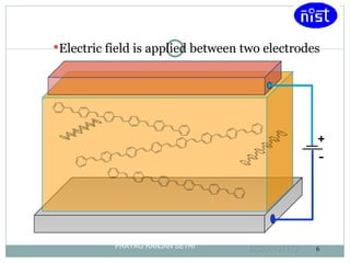
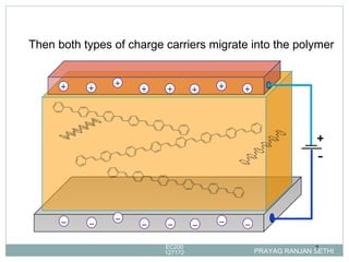
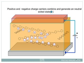
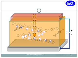
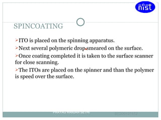
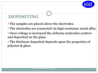


Light emitting polymers (LEPs) emit light when an electric field is applied. LEPs consist of a thin film of polymer sandwiched between an anode and cathode. When a voltage is applied, electrons are injected from the cathode and holes from the anode, which recombine and emit light radiatively. LEPs have advantages such as low energy consumption, suitability for large area lighting, simple fabrication process, and potential for flexible displays.


