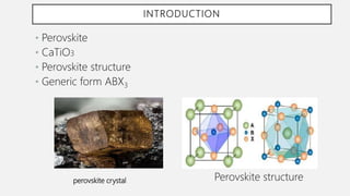
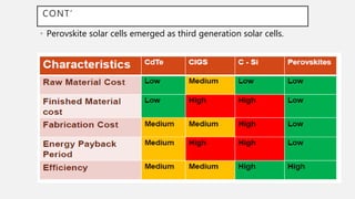
PEROVSKITE SOLAR CELLS
Center For Materials Engineering
By Kidist Worku
July,2019
INTRODUCTION
• Perovskite
• CaTiO3
• Perovskite structure
• Generic form ABX3
perovskite crystal Perovskite structure
CONT’
• Perovskite solar cells emerged as third generation solar cells.
CONT’
• Perovskite crystalline systems
CONT’
• Organometal halide perovskites, (e.g. methyl ammonium lead
iodide, MALI)
• Low cost, high efficiency solar cells
• MALI-based devices -introduced in 2009 PCE of 3.8%
• PSCs yielding PCE of up to > 20% in 2016
STRUCTURE OF PSCS
• Pseudo cubic lattice arrangement
• Large atomic or molecular cation (positively-charged) of type A in the
centre
• The corners occupied by atoms B (also positively-charged cations)
• Faces of the cube are occupied by a smaller atom X with negative charge
(anion).
CONT’
• Depending on which atoms/molecules are used in the
structure, perovskites can have an impressive array of
interesting properties, including
• Superconductivity,
• Spin-dependent transport (spintronics) and
• Catalytic properties.
PSC STRUCTURE
• Fluorine-doped tin oxide (FTO)/glass substrate
• TiO2 layer (TCO) = ETM
• CH3NH3PbI3 perovskite
• Spiro-MeOTAO = HTM
• Metallic electrodes (Au, Ag…)
CONSTRUCTION
PSC materials architecture
• Two most common PSC architectures
• Mesoscopic
• Planar
• Inverted architecture
CONT’
• Device configurations
• Transparent conducting glass
• hole- or electron-selective layer
• perovskite
• Front and back contact.
SEM IMAGE FOR PSC
MATERIAL CHOICE FOR PSC CONSTRUCTION
• .Transporters (HTM
& ETM)
• Charge carrier selectivity
• Matching of energy levels
• Degree of chemical
interaction
• Conductivity
• Light absorption
Contacts
• Light absorption
• Work function
• Chemical
contamination
Back Contact Electrode:
Gold; work function -5.1 eV
Silver; work function -4.26 eV
Aluminum; work function - 4.28
eV
Transparent Conductive Front
Contact:
Fluorine-doped tin oxide (FTO);
(work function: -4.4 eV)
Indium tin oxide (ITO);
(work function: -4.8 eV)
SYNTHESIS OF PSCS
• Simple and cost effective
• Two methods of processing
• variety of solvent techniques
• vapour deposition techniques.
• One step coating: CH3NH3I and
PbI2 are dissolved (ex. in gamma-
butyrolactone (GBL)),applied as
coating solution, drying and
annealing, spin coated
• Two step coating: TiO2 substrate
PbI2 solution is coated, form PbI2
film, then 2-proponol solution of
CH3NH3I is added to spinning
PbI2 film.
SOLUTION PROCESS TECHNIQUE
• Thermal evaporation technique requires high vacuum
condition
VAPOUR ASSISTED SOLUTION PROCESS
CHALLENGES AND PROGRESSES
• 1999, Tokyo, Japan- optical absorption layer for a solar cell using a
rare-earth-based perovskite compound.
• 2009, introduced CH3NH3PbI3 and the larger-bandgap analogue
CH3NH3PbBr3 as sensitizers for liquid-electrolyte-based DSSCs,
• The power conversion efficiency 3.8%, poor device stability due
to the rapid dissolution of the perovskite in the organic solvent.
• 2011- changing both the electrolyte formulation and the method of
depositing the perovskite, performance and stability attaining a PCE
of 6.5%
• 2014 -replaced electrolyte with a solid state hole conductor (or hole-
transporting material, HTM),
• PCE double, stability improved
CONT’
• Mesoporous scaffold made of Al2O3 instead of TiO2 produced similar if
not better, conversion efficiencies, even though Al2O3 is unable to assist
in electron extraction due to its large bandgap. (Lee et al, )
• This suggested that the perovskite itself transported the electrons. In
just a few years, PSCs have achieved cell efficiency surpassing the 22%
mark in 2016.
• PSC efficiencies have increased more rapidly than any other PV
technology, from 3.1% in 2009 to over 22.1% in 2016
DRAW BACKS OF THE CURRENT TECHNOLOGY
Moisture content
• Degradation of the HTM layer
• TiO2 nanoparticles can act as moisture barrier
• TiO2 act as photo catalyst and promote the degradation
of CH3NH3PbI into CH3NH2 and HI
CONT’
• Stability
• Humidity
• High temperature
• Formamidinium(FA) and partially replacing I- with Br-,
• Toxicity
• CH3NH3PbI3 in contact with polar solvents such as
water can convert to PbI2,
• moderately water-soluble, carcinogen, toxic
PSC MARKET
• Perovskite, a dirt-cheap material
• Cut the cost of a watt of solar-generating capacity by three-
quarters.
• This means that solar panels would cost just 10–20 cents per
watt.
• Top producers of PSCs
Perovskite solar cells

Perovskite solar cells

  • 1.
    PEROVSKITE SOLAR CELLS CenterFor Materials Engineering By Kidist Worku July,2019
  • 2.
    INTRODUCTION • Perovskite • CaTiO3 •Perovskite structure • Generic form ABX3 perovskite crystal Perovskite structure
  • 3.
    CONT’ • Perovskite solarcells emerged as third generation solar cells.
  • 4.
  • 5.
    CONT’ • Organometal halideperovskites, (e.g. methyl ammonium lead iodide, MALI) • Low cost, high efficiency solar cells • MALI-based devices -introduced in 2009 PCE of 3.8% • PSCs yielding PCE of up to > 20% in 2016
  • 6.
    STRUCTURE OF PSCS •Pseudo cubic lattice arrangement • Large atomic or molecular cation (positively-charged) of type A in the centre • The corners occupied by atoms B (also positively-charged cations) • Faces of the cube are occupied by a smaller atom X with negative charge (anion).
  • 7.
    CONT’ • Depending onwhich atoms/molecules are used in the structure, perovskites can have an impressive array of interesting properties, including • Superconductivity, • Spin-dependent transport (spintronics) and • Catalytic properties.
  • 8.
    PSC STRUCTURE • Fluorine-dopedtin oxide (FTO)/glass substrate • TiO2 layer (TCO) = ETM • CH3NH3PbI3 perovskite • Spiro-MeOTAO = HTM • Metallic electrodes (Au, Ag…)
  • 9.
    CONSTRUCTION PSC materials architecture •Two most common PSC architectures • Mesoscopic • Planar • Inverted architecture
  • 10.
    CONT’ • Device configurations •Transparent conducting glass • hole- or electron-selective layer • perovskite • Front and back contact.
  • 11.
  • 12.
    MATERIAL CHOICE FORPSC CONSTRUCTION • .Transporters (HTM & ETM) • Charge carrier selectivity • Matching of energy levels • Degree of chemical interaction • Conductivity • Light absorption Contacts • Light absorption • Work function • Chemical contamination Back Contact Electrode: Gold; work function -5.1 eV Silver; work function -4.26 eV Aluminum; work function - 4.28 eV Transparent Conductive Front Contact: Fluorine-doped tin oxide (FTO); (work function: -4.4 eV) Indium tin oxide (ITO); (work function: -4.8 eV)
  • 13.
    SYNTHESIS OF PSCS •Simple and cost effective • Two methods of processing • variety of solvent techniques • vapour deposition techniques.
  • 14.
    • One stepcoating: CH3NH3I and PbI2 are dissolved (ex. in gamma- butyrolactone (GBL)),applied as coating solution, drying and annealing, spin coated • Two step coating: TiO2 substrate PbI2 solution is coated, form PbI2 film, then 2-proponol solution of CH3NH3I is added to spinning PbI2 film. SOLUTION PROCESS TECHNIQUE
  • 15.
    • Thermal evaporationtechnique requires high vacuum condition VAPOUR ASSISTED SOLUTION PROCESS
  • 16.
    CHALLENGES AND PROGRESSES •1999, Tokyo, Japan- optical absorption layer for a solar cell using a rare-earth-based perovskite compound. • 2009, introduced CH3NH3PbI3 and the larger-bandgap analogue CH3NH3PbBr3 as sensitizers for liquid-electrolyte-based DSSCs, • The power conversion efficiency 3.8%, poor device stability due to the rapid dissolution of the perovskite in the organic solvent. • 2011- changing both the electrolyte formulation and the method of depositing the perovskite, performance and stability attaining a PCE of 6.5% • 2014 -replaced electrolyte with a solid state hole conductor (or hole- transporting material, HTM), • PCE double, stability improved
  • 17.
    CONT’ • Mesoporous scaffoldmade of Al2O3 instead of TiO2 produced similar if not better, conversion efficiencies, even though Al2O3 is unable to assist in electron extraction due to its large bandgap. (Lee et al, ) • This suggested that the perovskite itself transported the electrons. In just a few years, PSCs have achieved cell efficiency surpassing the 22% mark in 2016. • PSC efficiencies have increased more rapidly than any other PV technology, from 3.1% in 2009 to over 22.1% in 2016
  • 18.
    DRAW BACKS OFTHE CURRENT TECHNOLOGY Moisture content • Degradation of the HTM layer • TiO2 nanoparticles can act as moisture barrier • TiO2 act as photo catalyst and promote the degradation of CH3NH3PbI into CH3NH2 and HI
  • 19.
    CONT’ • Stability • Humidity •High temperature • Formamidinium(FA) and partially replacing I- with Br-, • Toxicity • CH3NH3PbI3 in contact with polar solvents such as water can convert to PbI2, • moderately water-soluble, carcinogen, toxic
  • 20.
    PSC MARKET • Perovskite,a dirt-cheap material • Cut the cost of a watt of solar-generating capacity by three- quarters. • This means that solar panels would cost just 10–20 cents per watt. • Top producers of PSCs

Editor's Notes

  • #8 Catalytic properties.  = TiO2 with water breaks down perovskite superconductivity== free career mobility,band gap ….
  • #10 Mesoscopic: 10– 30 nm layer of TiO2 ,hole blocking layer on a conductive transparent oxide such as FTO or ITO no mesoporous layer.