Downloaded 10,306 times


OLED technology uses organic light emitting diodes to create brighter, thinner, and more flexible displays. An OLED is composed of thin films of organic molecules that emit light when electricity is applied. The first OLED was developed in 1987, and since then OLEDs have been used in various displays. OLEDs offer advantages over LCDs like higher contrast, better viewing angles, and less power consumption. Major applications of OLEDs include televisions, smartphones, and laptops.
Introduction to OLED technology, its principles, and what constitutes OLEDs.
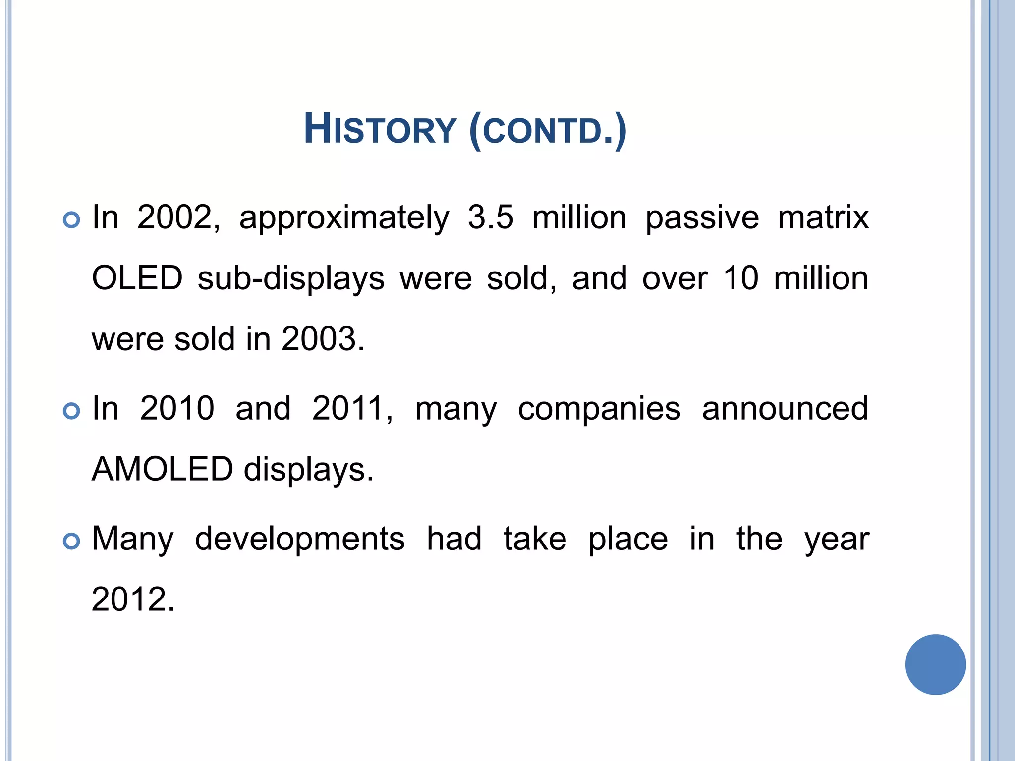
Timeline of OLED development, including key milestones from 1987 to 2012.
Characteristics of OLEDs including flexibility, emissive technology, low power, and display quality.
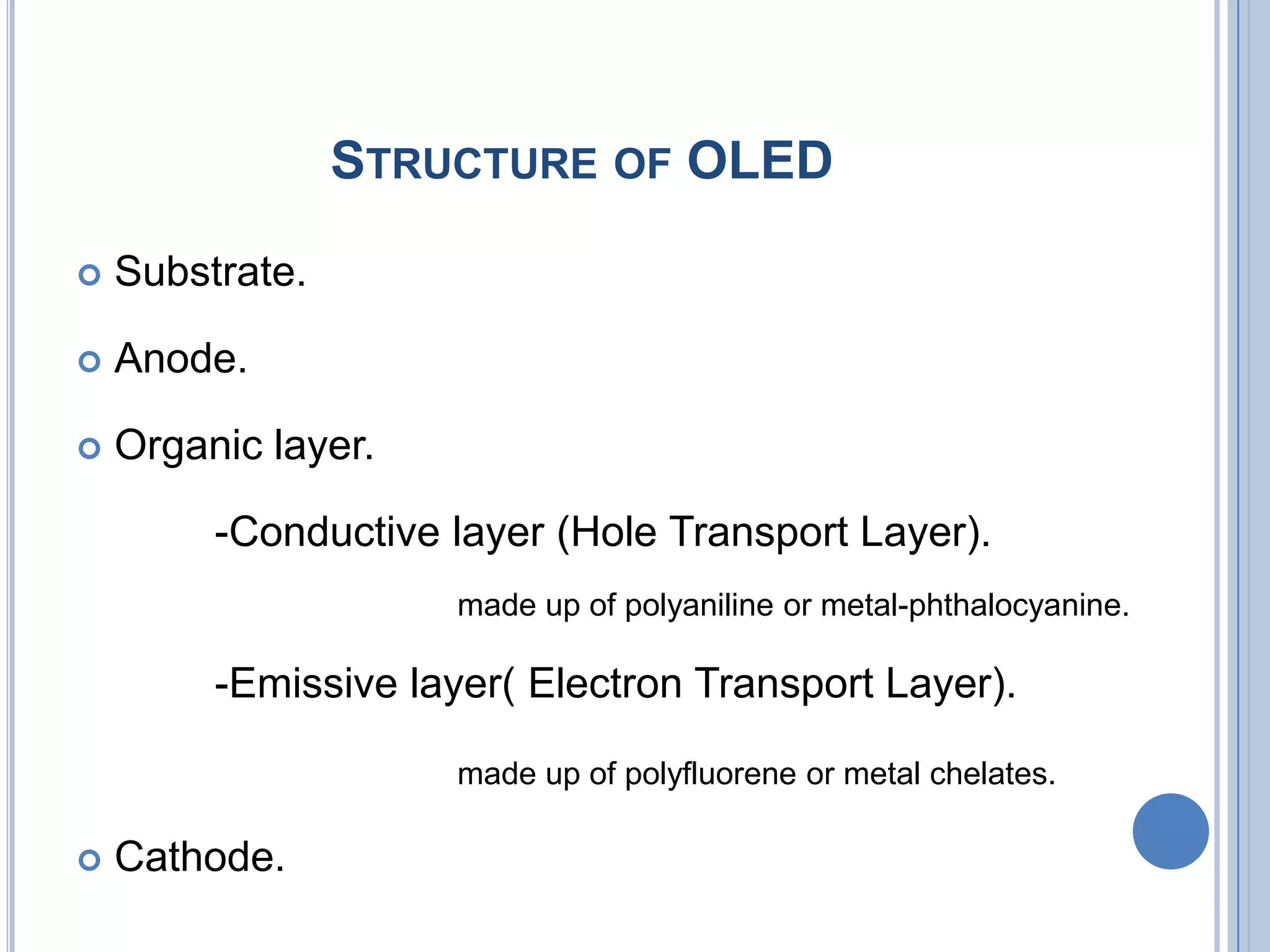
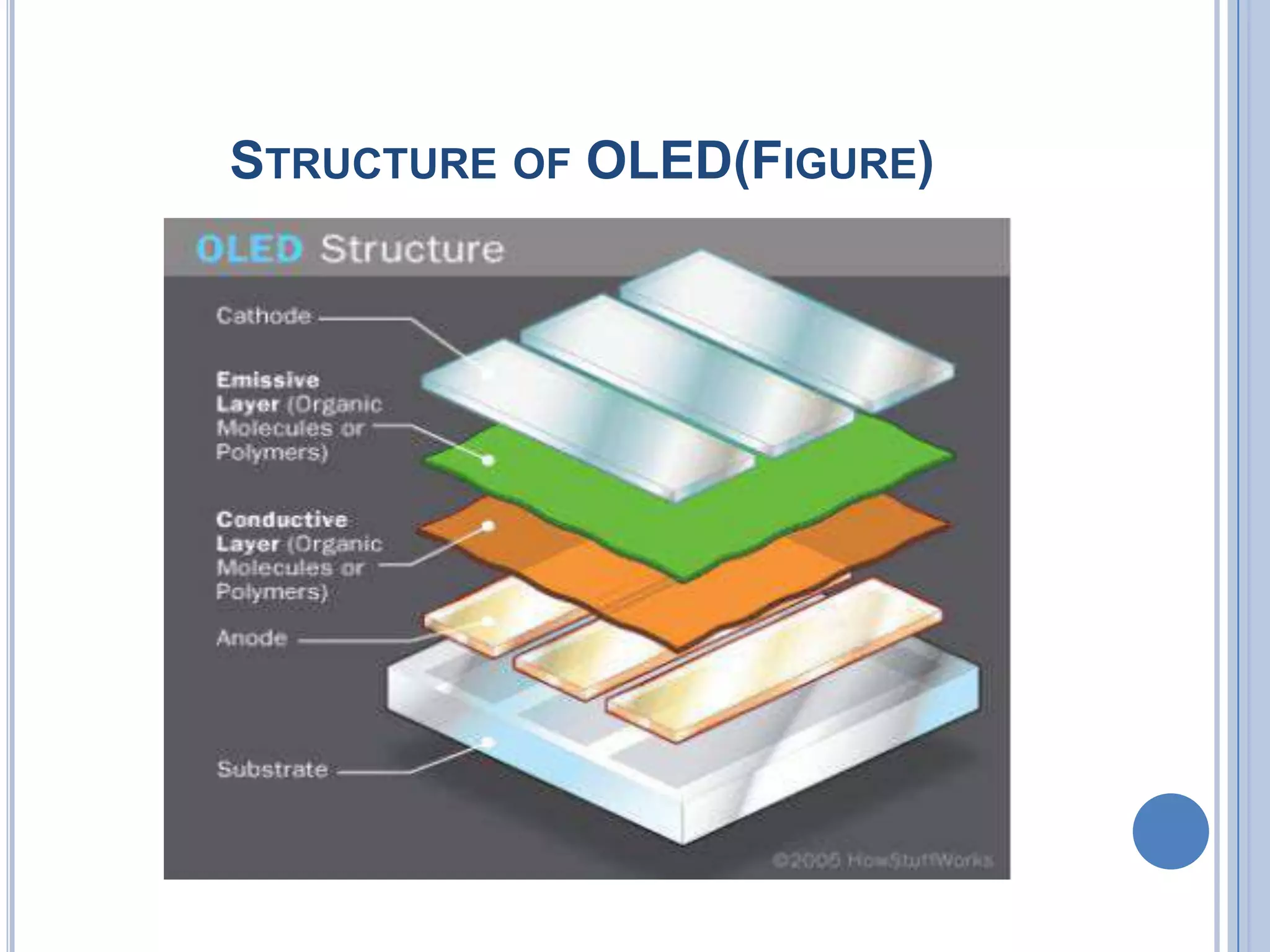
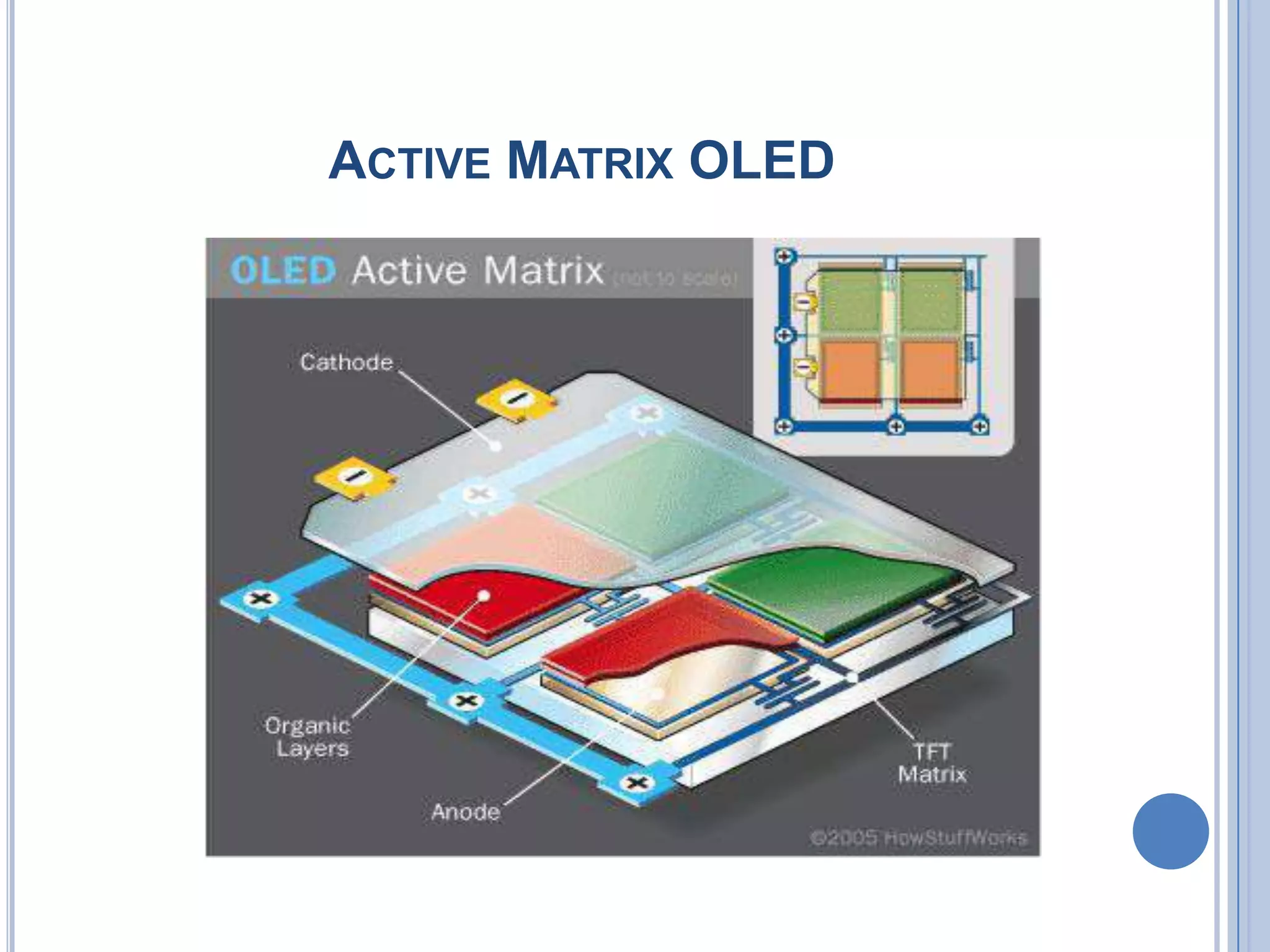
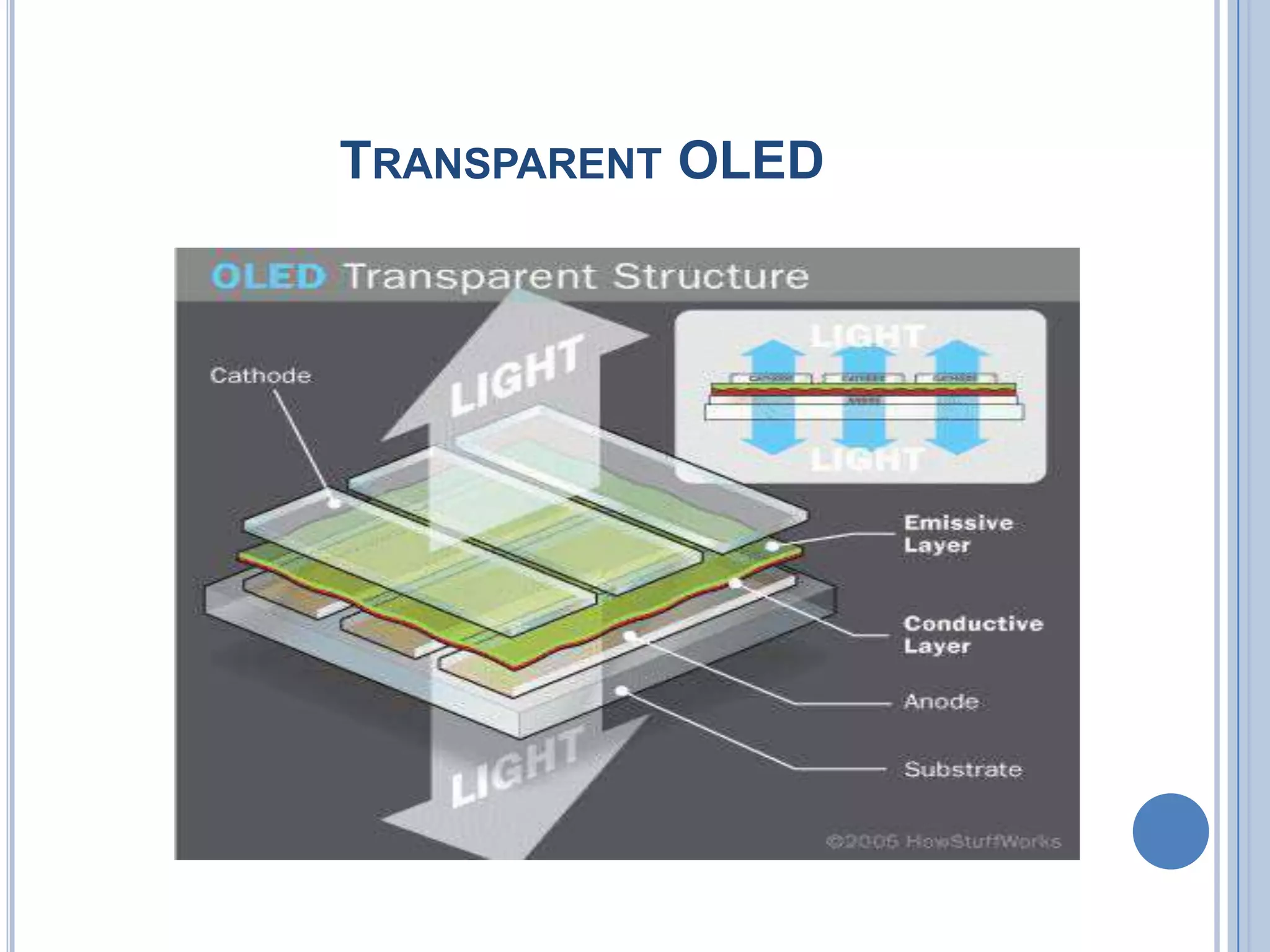
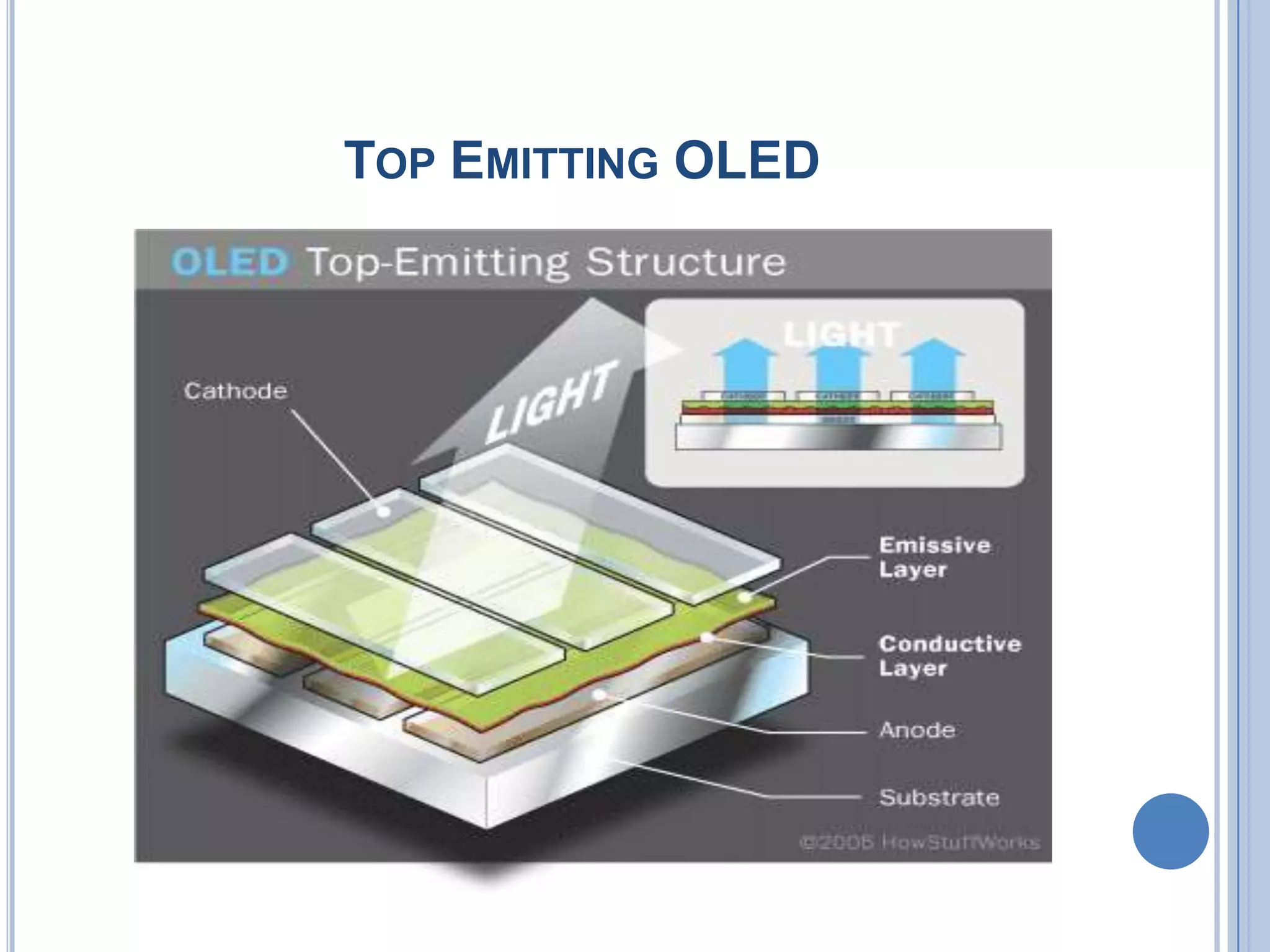
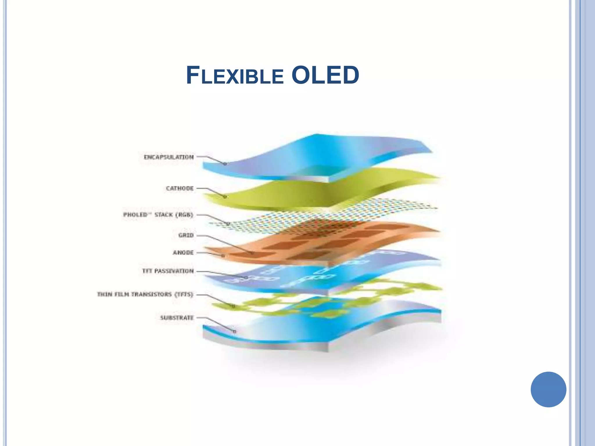
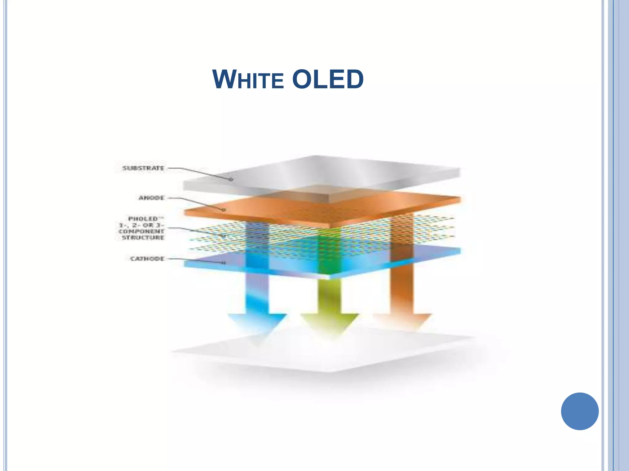
Components of OLEDs: substrate, anode, organic layers, and cathode.
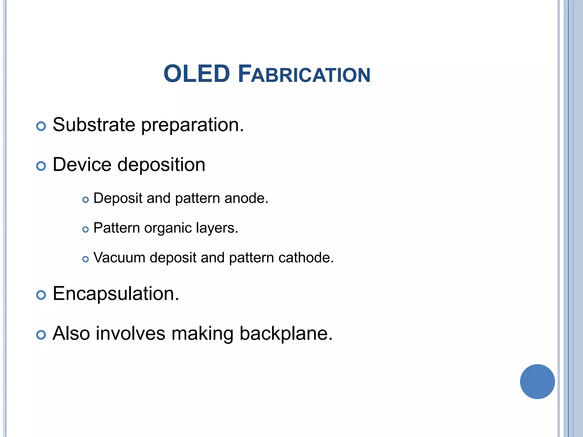
Processes involved in OLED fabrication including substrate preparation and deposition methods.
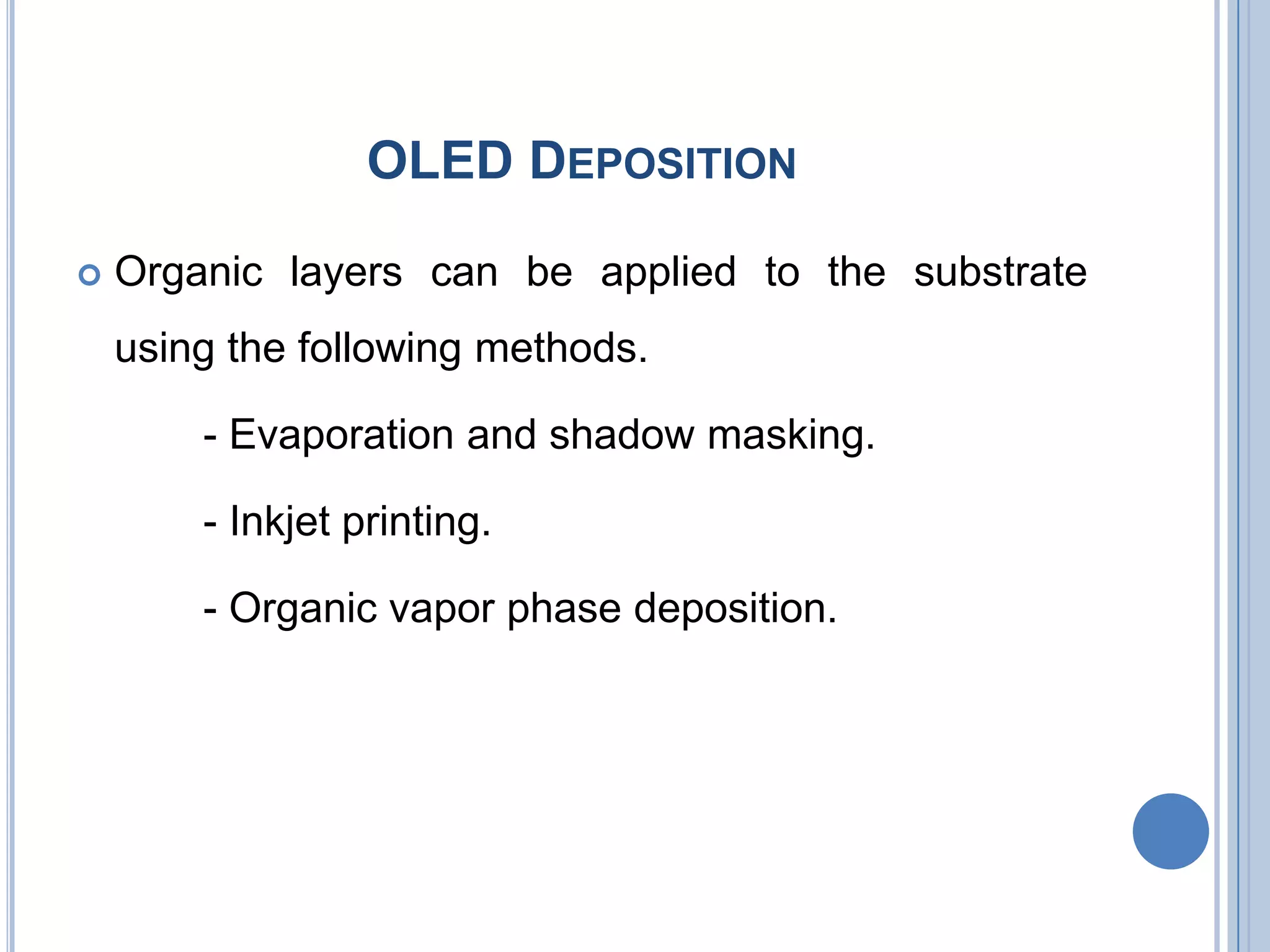
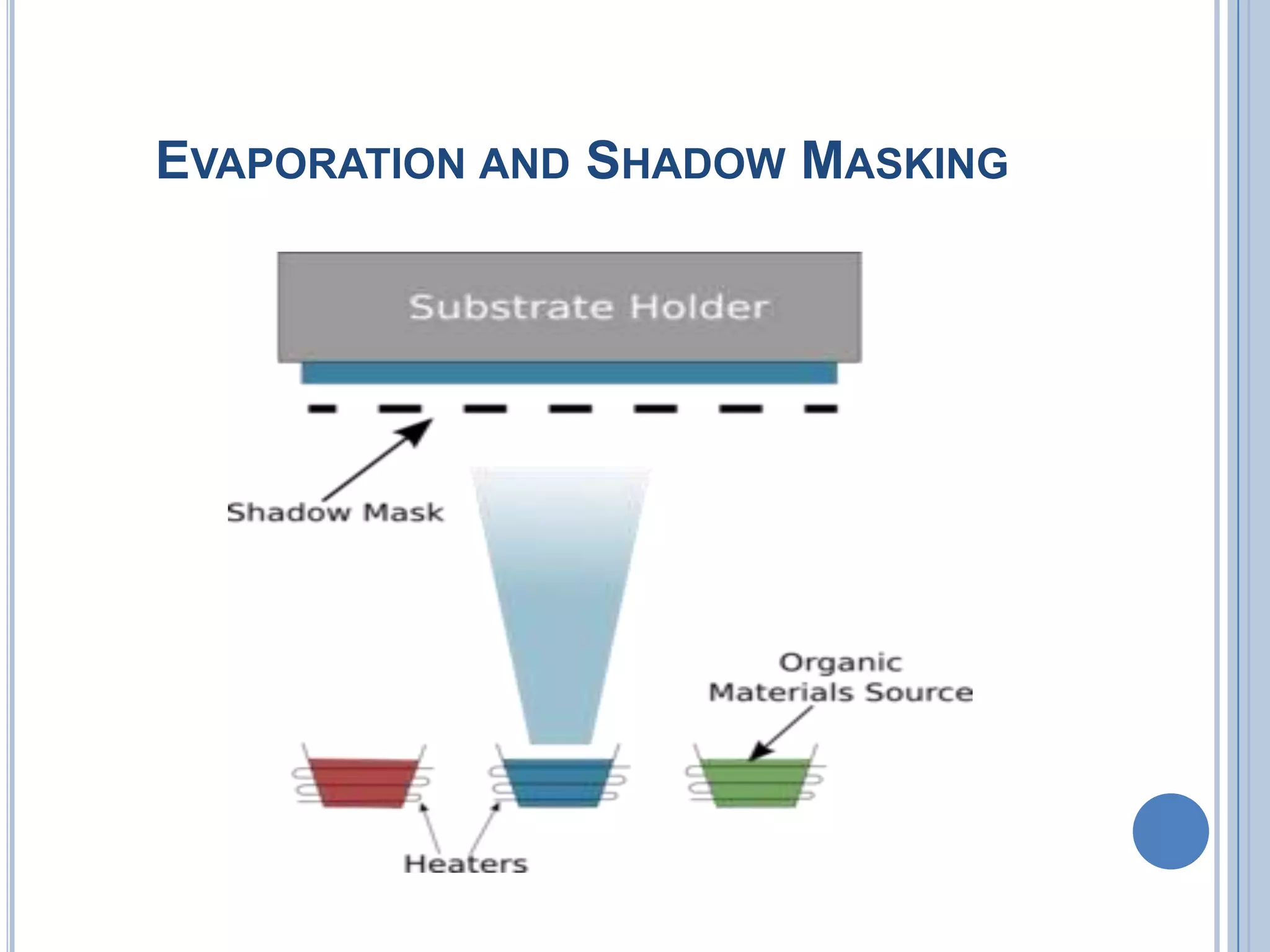
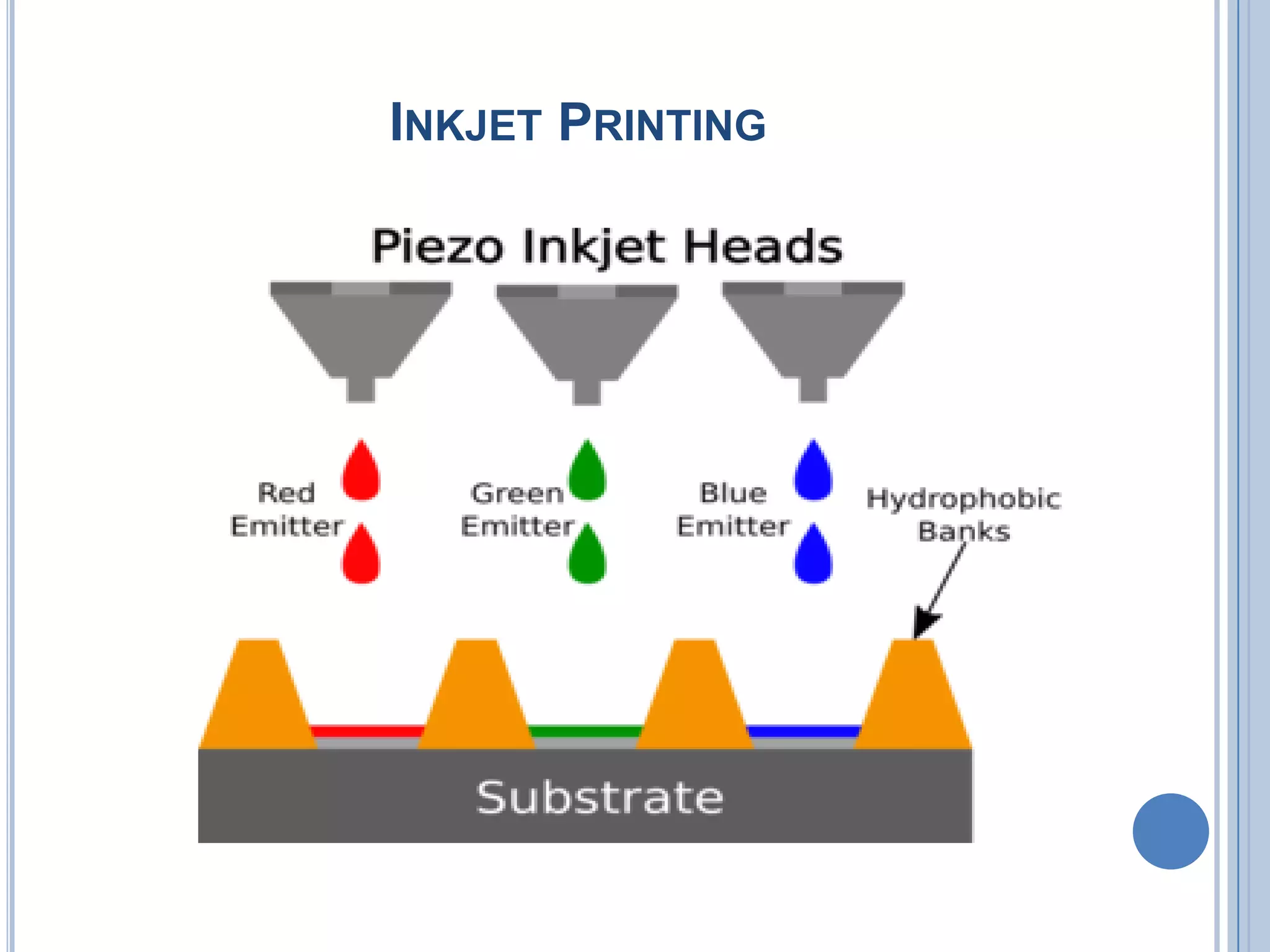
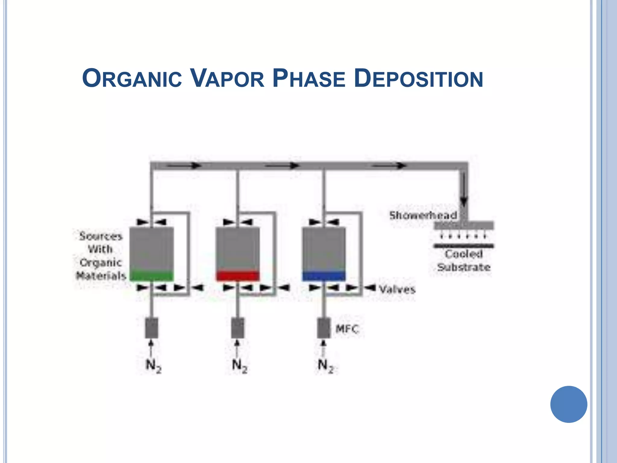
Methods for applying organic layers to substrates: evaporation, inkjet printing, and vapor phase.
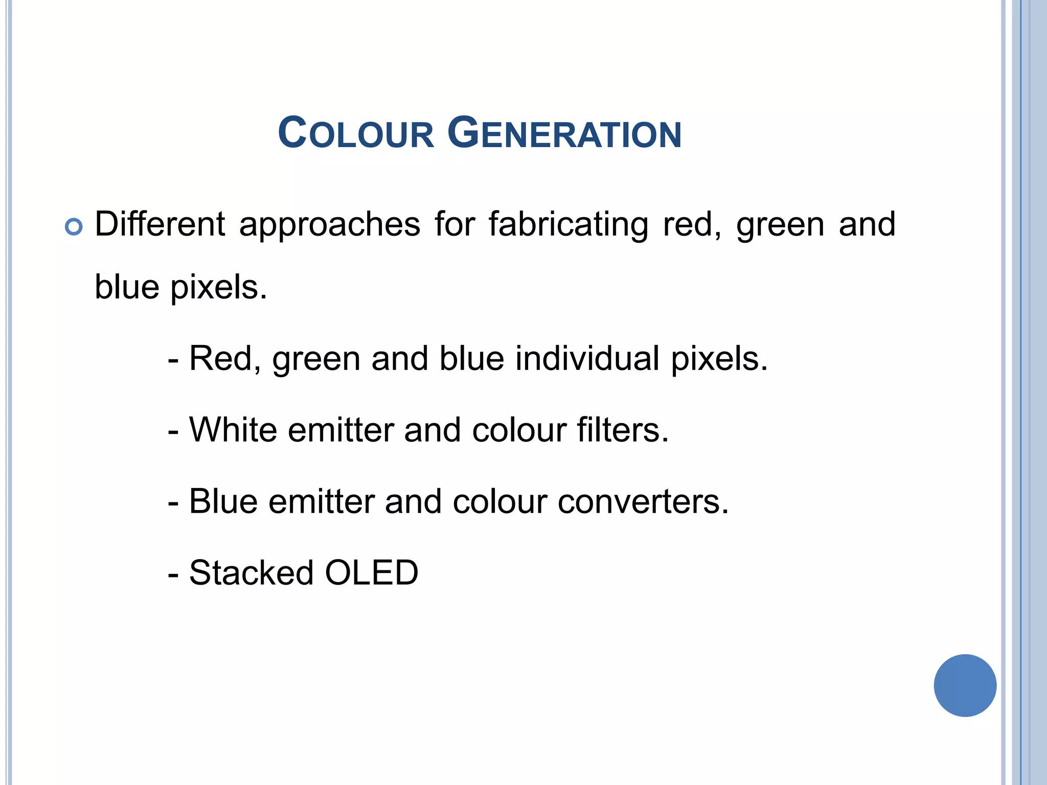
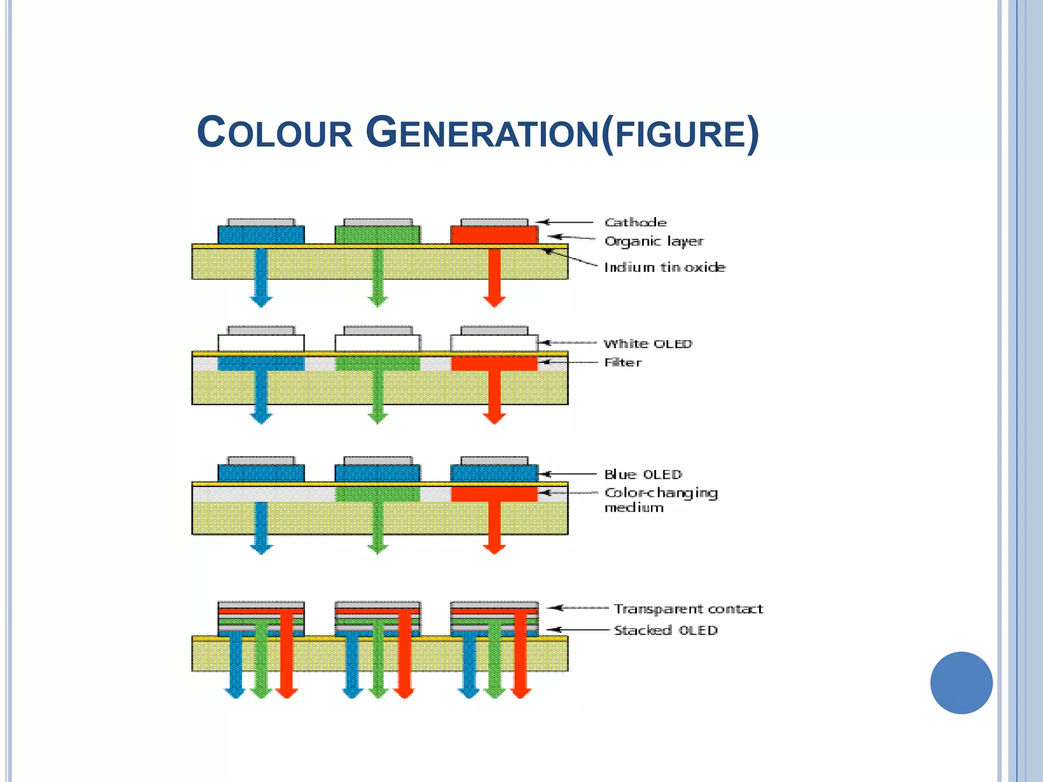
Techniques for producing RGB colors in OLED displays.
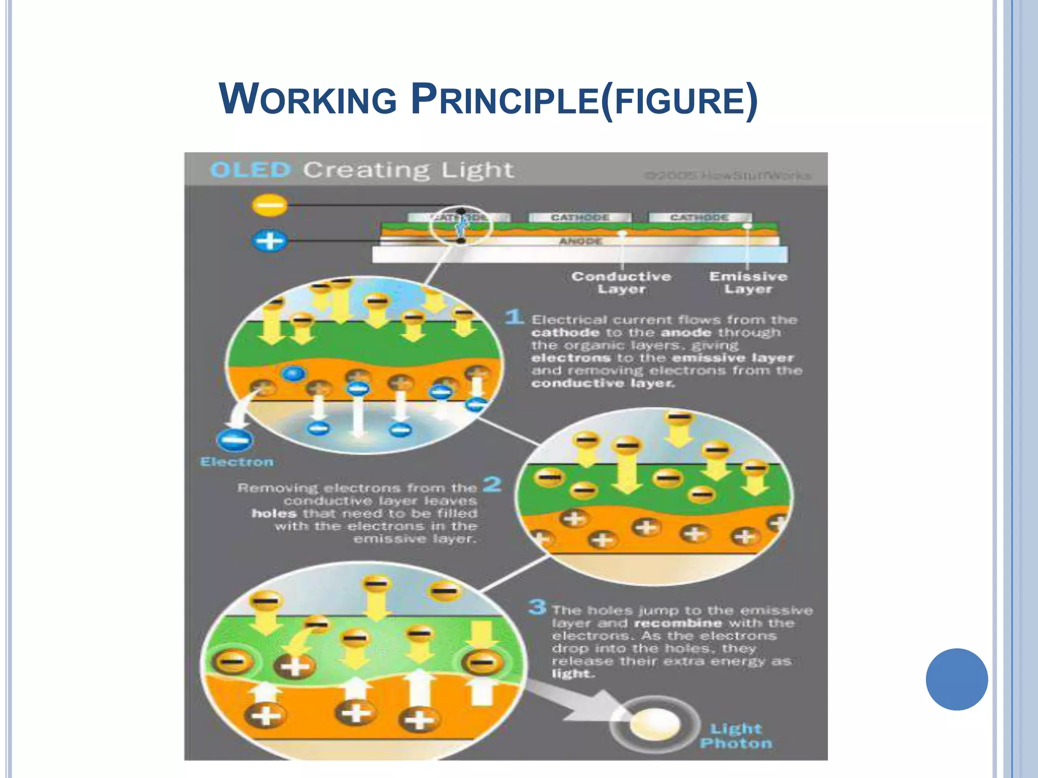
Mechanism of light emission in OLEDs through voltage application and electron flow.
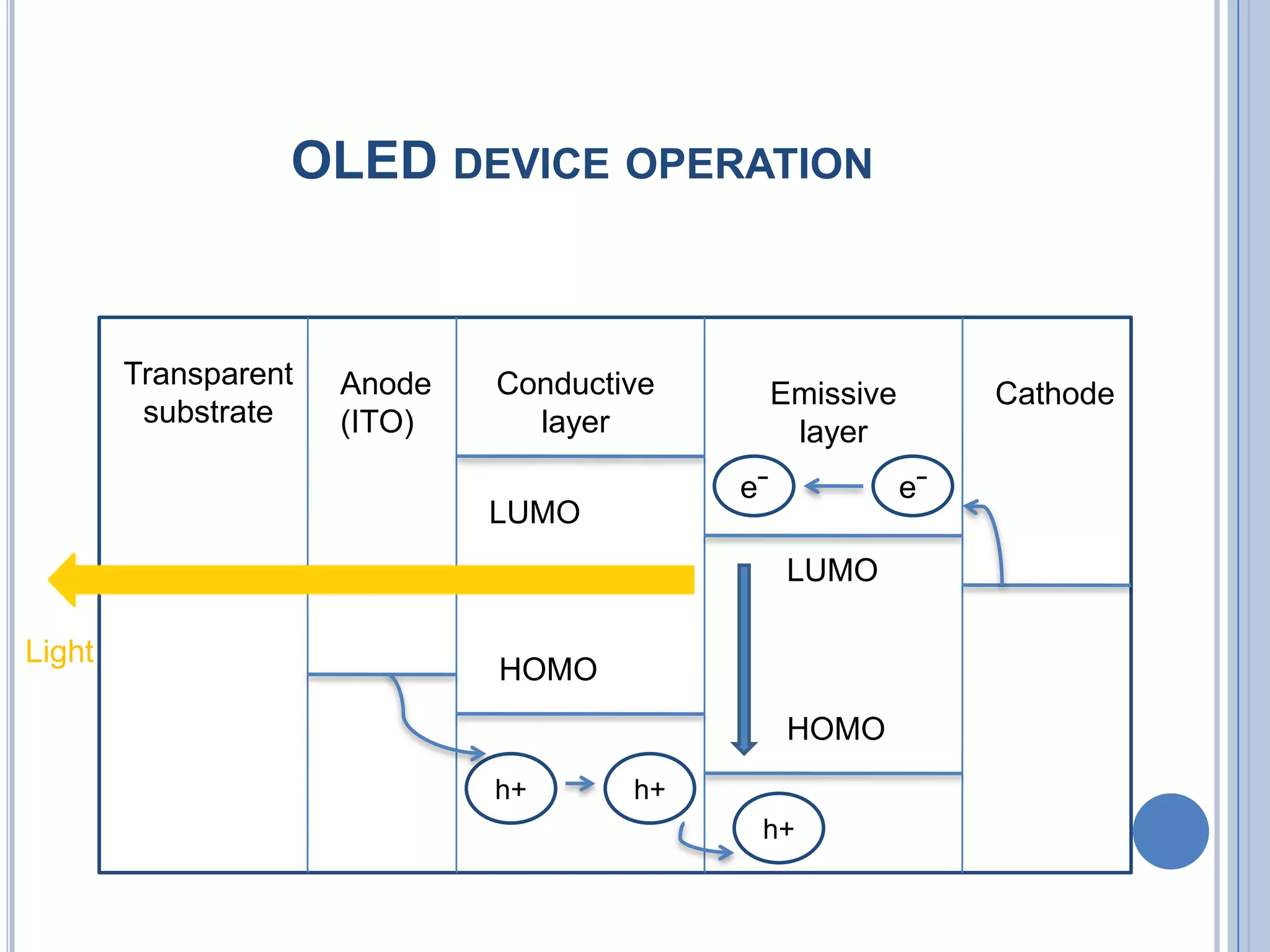
Detailed configuration of OLED device layers functioning together to emit light.
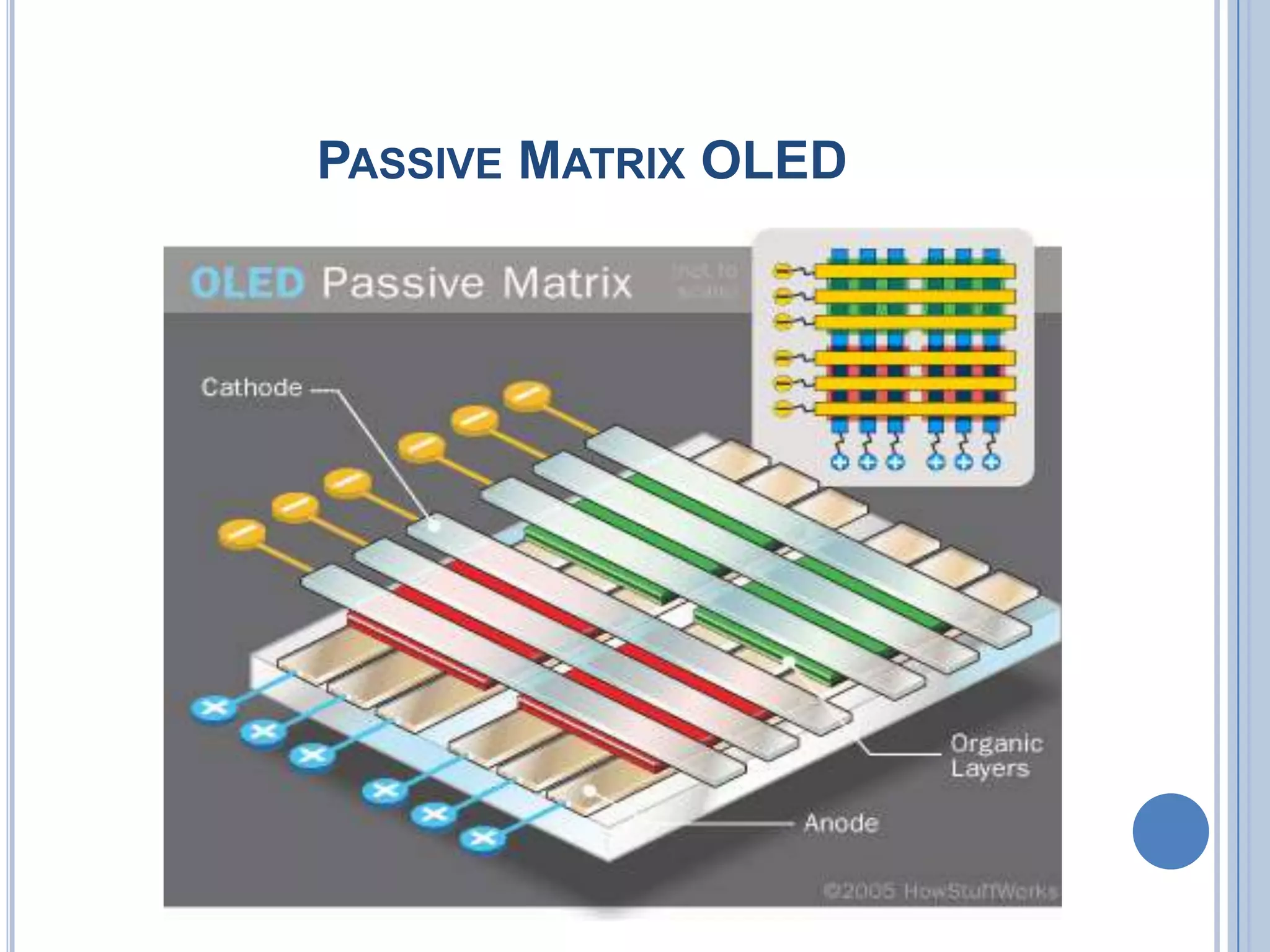
Six different types of OLEDs including PMOLED, AMOLED, TOLED, and more.
Benefits of OLED technology such as size, flexibility, response time, and resolution.
Drawbacks of OLEDs including cost, lifespan, water sensitivity, and color balance issues.
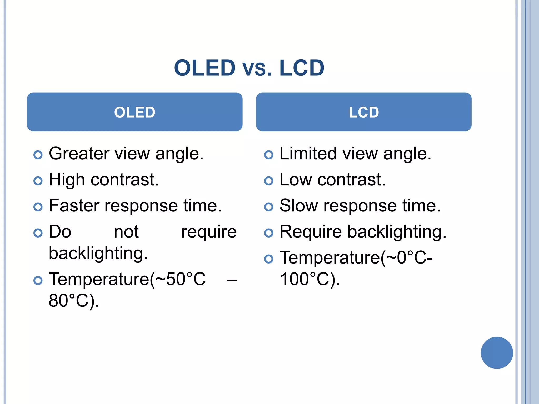
Comparison of OLED and LCD features like viewing angle, contrast, and response time.
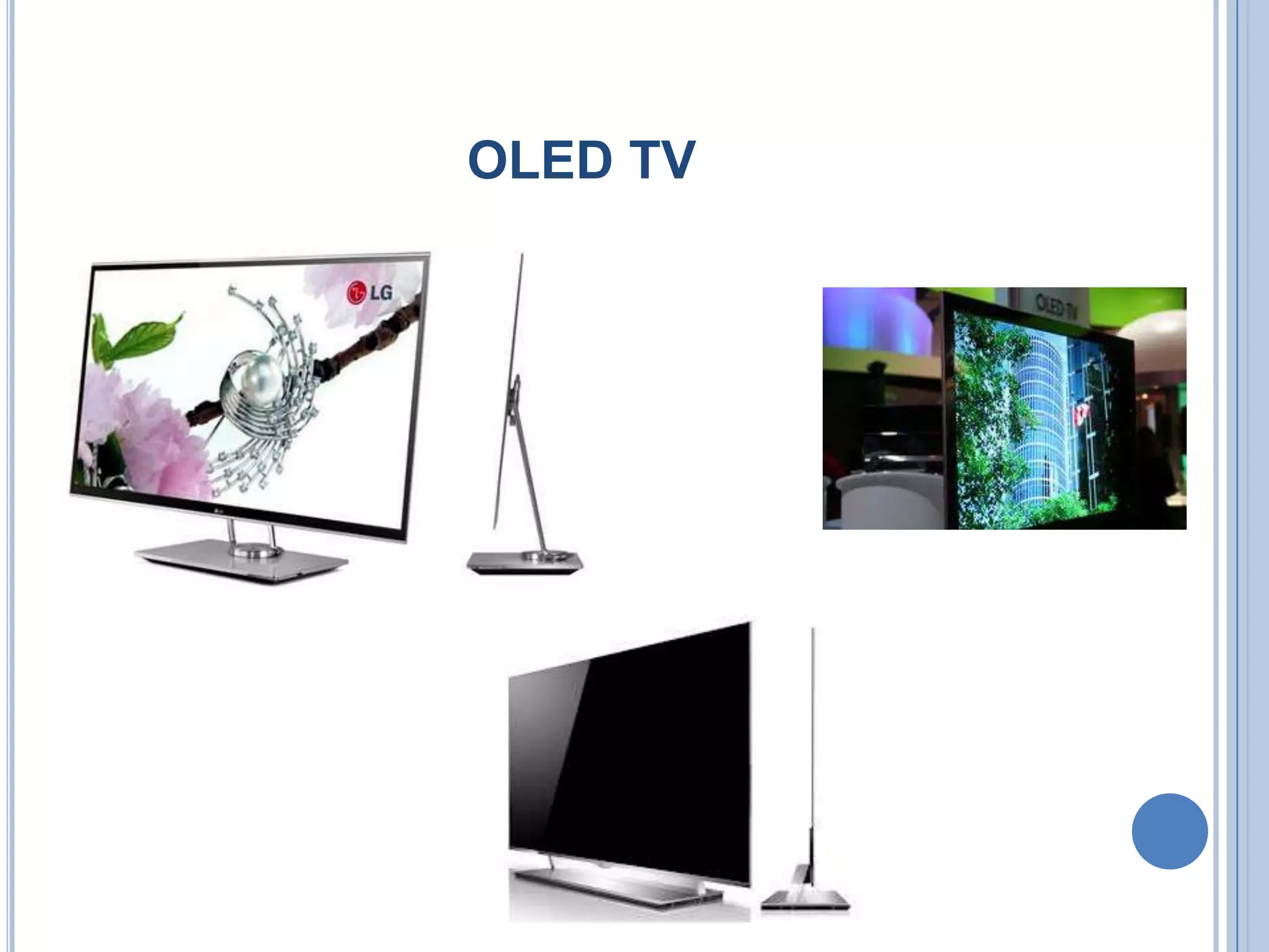
Key uses of OLED technology in TVs, mobile phones, and roll-top laptops.
Future prospects of OLEDs as advanced display solutions that overcome LCD limitations.


