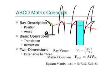
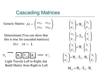
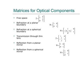
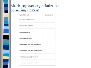
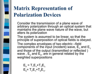
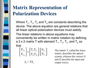
ABCD Matrix Concepts
 Ray Description
 Position
 Angle
 Basic Operations
 Translation
 Refraction
 Two-Dimensions
 Extensible to Three
Ray Vector
Matrix Operation
System Matrix
Cascading Matrices








⋅ℑ=







'
1
'
12
2
2 1
νν
xx






⋅ℜ=







2
2
2'
2
'
2
νν
xx






⋅ℜ=







1
1
1'
1
'
1
νν
xx
Generic Matrix:
Determinant (You can show that
this is true for cascaded matrices)
V1 R1 T12 R2 V’2
Light Travels Left to Right, but
Build Matrix from Right to Left
1






⋅ℜ⋅ℑ⋅ℜ=







1
1
1122'
2
'
2
νν
xx
112212 ℜ⋅ℑ⋅ℜ=Μ
Matrices for Optical Components
 Free space
 Refraction at a planar
boundary
 Refraction at a spherical
boundary
 Transmission through thin
lens
 Reflection from a planar
mirror
 Reflection from a spherical
mirror








=ℑ
10
1
n
d
( )








−−=ℜ
1
01
12
R
nn








−=ℑ 1
1
01
f






=ℜ
10
01








=ℜ
1
2
01
R






=ℜ
10
01
Properties of a system from its matrix
 If D = 0, all rays entering the input plane
from the same point emerge at the
output plane making the same angle with
the axis. The input plane must be the
focal plane of the system
 If B = 0, all rays leaving the point O at
the input will pass through the same point
I at the output. This is the condition for
object-image relationship to occur. In
addition, A or 1/D will give the transverse
magnification produced by the system
Properties of a system from its matrix
 If C = 0, all rays which enter the system
parallel to one another will emerge
parallel to one another in a new direction.
This is a telescopic system.
 If A = 0, all rays entering the system at
the same angle will pass through the
same point in the output plane. The
system brings a bundle of parallel rays to
a focus at the output plane.
Matrix representing polarization
A monochromatic plane wave of frequency f traveling
in the z direction is completely characterized by the
complex envelopes Exo=ax exp (jδx) and Eyo=ay exp (jδy)
of the x and y component of the electric field. It is
convenient to write these complex quantities in the
form of a column matrix,








=








=





= δδ
δ
j
y
x
j
y
j
x
yo
xo
ea
a
ea
ea
E
E
J y
x
Jones vector
Where δ = δy - δx
Matrix representing polarization –
degenerate state
Linearly polarized wave in x
direction
Linearly polarized wave, plane
of polarization making angle θ
with x axis
Left circularly polarized
Right circular polarized




0
1




θ
θ
sin
cos




j
1
2
1






− j
1
2
1
Optical Element Jones Matrix
linear horizontal polarizer
linear vertical polarizer
linear polarizer at
linear polarizer at -45°
quarter-wave plate, fast axis vertical
quarter-wave plate, fast axis horizontal
circular polarizer, right-handed
circular polarizer, left-handed
Matrix representing polarization –
polarizing element
Matrix Representation of
Polarization Devices
Consider the transmission of a plane wave of
arbitrary polarization through an optical system that
maintains the plane wave nature of the wave, but
alters its polarization
The system is assumed to be linear, so that the
principle of superposition of optical fields is obeyed.
The complex envelopes of two electric –field
components of the input (incident) wave, E1x and E1y
and those of the output (transmitted or reflected )
wave , E2x and E2y, are in general related by the
weighted superpositions
E2x = T11E1x+T12E1y
E2y= T21E1x+T22E1y,
Matrix Representation of
Polarization Devices
Where T11, T12, T21 and T22 are constants describing the
device. The above equation are general relations that
all linear optical polarization devices must satisfy.
The linear relations in above equations may
conveniently be written in matrix notation by defining
a 2 x 2 matrix T with element T11, T12, T21, and T22 so
that






=





2221
1211
2
2
TT
TT
E
E
y
x






y
x
E
E
1
1 The matrix T, called the Jones
matrix, describes the optical
system, whereas the vectors J1
and J2 describe the input and
output waves.J2 = TJ1
Optical Material
Anisotropic Material: A dielectric medium is
said to be anisotropic if its macroscopic
optical properties depends on direction.
The macroscopic properties of matter are of
course governed by the microscope
properties: The shape and orientation of
the individual molecules and the
organization of the molecules in space.
Optical material – continued..
The following is description of the positional and
orientational types of order inherent in several kinds
of optical materials .
– If the molecules are located in space at totally random
position and are themselves is isotropic or are oriented
along totally random direction , the medium is isotropic.
Gases, liquids, and amorphous solid are isotopic.
– If the molecule and the orientation are not totally random,
the medium is anisotropic, even if the position are totally
random. This is the case for liquid crystals, which have
orientation order but lack complete positional order.
Optical material – continued..
– If the molecules are organized in space according
to the regular periodic pattern and are oriented in
same direction, as in crystal, the medium is in
general anisotropic.
– Polycrystalline materials have a structure in the
form of disjoined crystalline grains that are
randomly oriented relative to the each other. The
grains are themselves generally anisotropic, but
their average macroscopic behavior is isotropic.
Optical material – continued…
Polaroid Material
– Polaroid is the trade name for the most commonly
used dichroic material.
– It selectively absorbs light from one plane, typically
transmitting less than 1% through a sheet of
polaroid. It may transmit more than 80% of light in
the perpendicular plane.
– Polaroid materials accomplish polarization by
dichroism. At angles other than 90°, the
transmitted intensity is given by the Law of Malus.
Optical material – continued..
Dichroism
– Causes visible light to split into distinct
beams of different wavelengths, or
– One in which light rays having different
polarizations are absorbed by different
amount
There is a distinct difference between
dichroism and dispersion
Law of Malus
When unpolarized light passes through a polarizer,
the light intensity—proportional to the square of its
electric field strength—is reduced, since only the E-
field component along the transmission axis of the
polarizer is passed.
When linearly polarized light is directed through a
polarizer and the direction of the E-field is at an angle
θ to the transmission axis of the polarizer, the light
intensity is likewise reduced. The reduction in
intensity is expressed by the law of Malus, I=I0cos2
θ
Law of Malus
Polarization by reflection
Unpolarized light can also undergo polarization by
reflection off nonmetallic surfaces. The extent to
which polarization occurs is dependent upon the
angle at which the light approaches the surface and
upon the material which the surface is made of.
A person viewing objects by means of light reflected
off nonmetallic surfaces will often perceive a glare if
the extent of polarization is large.
Metallic surfaces reflect light with a variety of
vibrational directions; such reflected light is
unpolarized.
•For normal incidence case, the reflection
coefficient and transmission coefficient is
independent of polarization, because the
electric and magnetic fields are both always
tangential to the boundary
•This is not the case for wave with an
oblique angle, because the polarization is
not always tangential to the surface or
boundary
Polarization by reflection
Brewster’s angle is an angle of incidence at which
light with a particular polarization is perfectly
transmitted through a transparent nonmetalic
surfaces.
θB = arctan (n2/n1)
The angle of reflection and angle of refraction adds
up to be 90o
Light that reflects from a surface at this angle is
entirely polarized perpendicular to the incident plane -
GLARE
If the angle is not exactly Brewster’s angle the
reflected ray will only be partially polarized
Polarization by reflection
Glare from water surface Glare blocked by vertical polarizer
Polarization by reflection
There are two types of polarization relative to the plane
of incidence
1. Parallel polarization
(TM polarization)
2. Perpendicular polarization
(TE polarization)
Plane of polarization is defined by the plane containing
the normal of the boundary and the direction of
propagation of the incident wave.
Relative to E
Polarization by reflection
Perpendicular polarization
The reflection and transmission coefficients are given by
θηθη
θηθη
coscos
coscos
12
12
+
−
==Γ
⊥
⊥
⊥
i
ti
i
o
r
o
E
E
ti
i
i
o
t
o
E
E
θηθη
θη
τ
coscos
cos2
12
2
+
==
⊥
⊥
⊥
1+Γ= ⊥⊥τ
it
it
i
o
r
o
E
E
θηθη
θηθη
coscos
coscos
12
12
||
||
||
+
−
==Γ
it
i
i
o
t
o
E
E
θηθη
θη
τ
coscos
cos2
12
2
||
||
||
+
==
Parallel polarization
The Fresnel reflection and transmission coefficients are
given by
1|||| +Γ=τ
Polarization by refraction
•Polarization can also occur by
the refraction of light. Refraction
occurs when a beam of light
passes from one material into
another material.
•At the surface of the two
materials, the path of the beam
changes its direction. The
refracted beam acquires some
degree of polarization
Birefringence
Birefringence, or double refraction, is the division
of a ray of light into two rays (the ordinary ray and the
extraordinary ray) when it passes through certain
types of material, such as calcite crystals, depending
on the polarization of the light.
This is explained by assigning two different
refractive indices to the material for different
polarizations. The birefringence is quantified by:
Δn = ne - no
where no is the refractive index for the ordinary ray and ne is the
refractive index for the extraordinary ray.
Birefringence
When a beam of ordinary unpolarized light is incident
on a calcite or quartz crystal, there will be, in addition
to the reflected beam, two refracted beams in place
of the usual single one observed, e.g., in glass.
This phenomenon is called double refraction or
birefringence.
Upon measuring the angles of refraction for different
angles of incidence, one finds that Snell's law of
refraction holds for one ray but not for the other. The
ray for which the law holds is called the ordinary ray
and the other is called the extraordinary ray.
Birefringence
Unpolarized light entering a birefringent
crystal is split into two linearly polarized
beams which are refracted by different
amounts.
There are two refractive indices
Optic axis: this is the direction within the crystal along which
there is no double refraction.
Birefringence
Application of polarization
Linear polarizar
– The linear polarizer selectively removes all
or most of the E fields in a given direction,
while allowing fields in the perpendicular
direction to be transmitted.
– In most cases, the selectivity is not 100%
efficient, so the transmitted light is partially
polarized
Application of polarization
Phase retarder
– The phase retarder does not remove either
of the component orthogonal E fields but
introduces a phase difference between
them.
– If light corresponding to each vibration
travels with different speeds through such
a retardation plate, there will be cumulative
phase difference between the two waves
Application of polarization
Rotator
– The rotator has the effect of rotating the
direction of linearly polarized light incident
on it by some particular angle.
– The effect of the rotator element is to
transmit linearly polarized light whose
direction of vibration has rotated
counterclockwise or vice versa, by an
angle θ

Lecture 9a 2013_

  • 1.
    ABCD Matrix Concepts Ray Description  Position  Angle  Basic Operations  Translation  Refraction  Two-Dimensions  Extensible to Three Ray Vector Matrix Operation System Matrix
  • 2.
    Cascading Matrices         ⋅ℑ=        ' 1 ' 12 2 2 1 νν xx       ⋅ℜ=        2 2 2' 2 ' 2 νν xx       ⋅ℜ=        1 1 1' 1 ' 1 νν xx GenericMatrix: Determinant (You can show that this is true for cascaded matrices) V1 R1 T12 R2 V’2 Light Travels Left to Right, but Build Matrix from Right to Left 1       ⋅ℜ⋅ℑ⋅ℜ=        1 1 1122' 2 ' 2 νν xx 112212 ℜ⋅ℑ⋅ℜ=Μ
  • 3.
    Matrices for OpticalComponents  Free space  Refraction at a planar boundary  Refraction at a spherical boundary  Transmission through thin lens  Reflection from a planar mirror  Reflection from a spherical mirror         =ℑ 10 1 n d ( )         −−=ℜ 1 01 12 R nn         −=ℑ 1 1 01 f       =ℜ 10 01         =ℜ 1 2 01 R       =ℜ 10 01
  • 4.
    Properties of asystem from its matrix  If D = 0, all rays entering the input plane from the same point emerge at the output plane making the same angle with the axis. The input plane must be the focal plane of the system  If B = 0, all rays leaving the point O at the input will pass through the same point I at the output. This is the condition for object-image relationship to occur. In addition, A or 1/D will give the transverse magnification produced by the system
  • 5.
    Properties of asystem from its matrix  If C = 0, all rays which enter the system parallel to one another will emerge parallel to one another in a new direction. This is a telescopic system.  If A = 0, all rays entering the system at the same angle will pass through the same point in the output plane. The system brings a bundle of parallel rays to a focus at the output plane.
  • 6.
    Matrix representing polarization Amonochromatic plane wave of frequency f traveling in the z direction is completely characterized by the complex envelopes Exo=ax exp (jδx) and Eyo=ay exp (jδy) of the x and y component of the electric field. It is convenient to write these complex quantities in the form of a column matrix,         =         =      = δδ δ j y x j y j x yo xo ea a ea ea E E J y x Jones vector Where δ = δy - δx
  • 7.
    Matrix representing polarization– degenerate state Linearly polarized wave in x direction Linearly polarized wave, plane of polarization making angle θ with x axis Left circularly polarized Right circular polarized     0 1     θ θ sin cos     j 1 2 1       − j 1 2 1
  • 8.
    Optical Element JonesMatrix linear horizontal polarizer linear vertical polarizer linear polarizer at linear polarizer at -45° quarter-wave plate, fast axis vertical quarter-wave plate, fast axis horizontal circular polarizer, right-handed circular polarizer, left-handed Matrix representing polarization – polarizing element
  • 9.
    Matrix Representation of PolarizationDevices Consider the transmission of a plane wave of arbitrary polarization through an optical system that maintains the plane wave nature of the wave, but alters its polarization The system is assumed to be linear, so that the principle of superposition of optical fields is obeyed. The complex envelopes of two electric –field components of the input (incident) wave, E1x and E1y and those of the output (transmitted or reflected ) wave , E2x and E2y, are in general related by the weighted superpositions E2x = T11E1x+T12E1y E2y= T21E1x+T22E1y,
  • 10.
    Matrix Representation of PolarizationDevices Where T11, T12, T21 and T22 are constants describing the device. The above equation are general relations that all linear optical polarization devices must satisfy. The linear relations in above equations may conveniently be written in matrix notation by defining a 2 x 2 matrix T with element T11, T12, T21, and T22 so that       =      2221 1211 2 2 TT TT E E y x       y x E E 1 1 The matrix T, called the Jones matrix, describes the optical system, whereas the vectors J1 and J2 describe the input and output waves.J2 = TJ1
  • 11.
    Optical Material Anisotropic Material:A dielectric medium is said to be anisotropic if its macroscopic optical properties depends on direction. The macroscopic properties of matter are of course governed by the microscope properties: The shape and orientation of the individual molecules and the organization of the molecules in space.
  • 12.
    Optical material –continued.. The following is description of the positional and orientational types of order inherent in several kinds of optical materials . – If the molecules are located in space at totally random position and are themselves is isotropic or are oriented along totally random direction , the medium is isotropic. Gases, liquids, and amorphous solid are isotopic. – If the molecule and the orientation are not totally random, the medium is anisotropic, even if the position are totally random. This is the case for liquid crystals, which have orientation order but lack complete positional order.
  • 13.
    Optical material –continued.. – If the molecules are organized in space according to the regular periodic pattern and are oriented in same direction, as in crystal, the medium is in general anisotropic. – Polycrystalline materials have a structure in the form of disjoined crystalline grains that are randomly oriented relative to the each other. The grains are themselves generally anisotropic, but their average macroscopic behavior is isotropic.
  • 14.
    Optical material –continued… Polaroid Material – Polaroid is the trade name for the most commonly used dichroic material. – It selectively absorbs light from one plane, typically transmitting less than 1% through a sheet of polaroid. It may transmit more than 80% of light in the perpendicular plane. – Polaroid materials accomplish polarization by dichroism. At angles other than 90°, the transmitted intensity is given by the Law of Malus.
  • 15.
    Optical material –continued.. Dichroism – Causes visible light to split into distinct beams of different wavelengths, or – One in which light rays having different polarizations are absorbed by different amount There is a distinct difference between dichroism and dispersion
  • 16.
    Law of Malus Whenunpolarized light passes through a polarizer, the light intensity—proportional to the square of its electric field strength—is reduced, since only the E- field component along the transmission axis of the polarizer is passed. When linearly polarized light is directed through a polarizer and the direction of the E-field is at an angle θ to the transmission axis of the polarizer, the light intensity is likewise reduced. The reduction in intensity is expressed by the law of Malus, I=I0cos2 θ
  • 17.
  • 18.
    Polarization by reflection Unpolarizedlight can also undergo polarization by reflection off nonmetallic surfaces. The extent to which polarization occurs is dependent upon the angle at which the light approaches the surface and upon the material which the surface is made of. A person viewing objects by means of light reflected off nonmetallic surfaces will often perceive a glare if the extent of polarization is large. Metallic surfaces reflect light with a variety of vibrational directions; such reflected light is unpolarized.
  • 19.
    •For normal incidencecase, the reflection coefficient and transmission coefficient is independent of polarization, because the electric and magnetic fields are both always tangential to the boundary •This is not the case for wave with an oblique angle, because the polarization is not always tangential to the surface or boundary Polarization by reflection
  • 20.
    Polarization by reflection Brewster’sangle is an angle of incidence at which light with a particular polarization is perfectly transmitted through a transparent nonmetalic surfaces. θB = arctan (n2/n1) The angle of reflection and angle of refraction adds up to be 90o Light that reflects from a surface at this angle is entirely polarized perpendicular to the incident plane - GLARE If the angle is not exactly Brewster’s angle the reflected ray will only be partially polarized
  • 21.
  • 22.
    Glare from watersurface Glare blocked by vertical polarizer Polarization by reflection
  • 23.
    There are twotypes of polarization relative to the plane of incidence 1. Parallel polarization (TM polarization) 2. Perpendicular polarization (TE polarization) Plane of polarization is defined by the plane containing the normal of the boundary and the direction of propagation of the incident wave. Relative to E Polarization by reflection
  • 24.
  • 25.
    Perpendicular polarization The reflectionand transmission coefficients are given by θηθη θηθη coscos coscos 12 12 + − ==Γ ⊥ ⊥ ⊥ i ti i o r o E E ti i i o t o E E θηθη θη τ coscos cos2 12 2 + == ⊥ ⊥ ⊥ 1+Γ= ⊥⊥τ
  • 26.
  • 27.
    Polarization by refraction •Polarizationcan also occur by the refraction of light. Refraction occurs when a beam of light passes from one material into another material. •At the surface of the two materials, the path of the beam changes its direction. The refracted beam acquires some degree of polarization
  • 28.
    Birefringence Birefringence, or doublerefraction, is the division of a ray of light into two rays (the ordinary ray and the extraordinary ray) when it passes through certain types of material, such as calcite crystals, depending on the polarization of the light. This is explained by assigning two different refractive indices to the material for different polarizations. The birefringence is quantified by: Δn = ne - no where no is the refractive index for the ordinary ray and ne is the refractive index for the extraordinary ray.
  • 29.
    Birefringence When a beamof ordinary unpolarized light is incident on a calcite or quartz crystal, there will be, in addition to the reflected beam, two refracted beams in place of the usual single one observed, e.g., in glass. This phenomenon is called double refraction or birefringence. Upon measuring the angles of refraction for different angles of incidence, one finds that Snell's law of refraction holds for one ray but not for the other. The ray for which the law holds is called the ordinary ray and the other is called the extraordinary ray.
  • 30.
    Birefringence Unpolarized light enteringa birefringent crystal is split into two linearly polarized beams which are refracted by different amounts. There are two refractive indices Optic axis: this is the direction within the crystal along which there is no double refraction.
  • 31.
  • 32.
    Application of polarization Linearpolarizar – The linear polarizer selectively removes all or most of the E fields in a given direction, while allowing fields in the perpendicular direction to be transmitted. – In most cases, the selectivity is not 100% efficient, so the transmitted light is partially polarized
  • 33.
    Application of polarization Phaseretarder – The phase retarder does not remove either of the component orthogonal E fields but introduces a phase difference between them. – If light corresponding to each vibration travels with different speeds through such a retardation plate, there will be cumulative phase difference between the two waves
  • 34.
    Application of polarization Rotator –The rotator has the effect of rotating the direction of linearly polarized light incident on it by some particular angle. – The effect of the rotator element is to transmit linearly polarized light whose direction of vibration has rotated counterclockwise or vice versa, by an angle θ