3
Input-Output Organization
Computer OrganizationComputer Architectures Lab
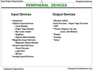
INPUT/OUTPUT INTERFACE
Input/Output Interfaces
• Provides a method for transferring information between internal
storage (such as memory and CPU registers) and external I/O
devices
• Resolves the differences between the computer and peripheral
devices
– Peripherals - Electromechanical Devices
– CPU or Memory - Electronic Device
– Data Transfer Rate
» Peripherals - Usually slower
» CPU or Memory - Usually faster than peripherals
• Some kinds of Synchronization mechanism may be needed
– Unit of Information
» Peripherals – Byte, Block, …
» CPU or Memory – Word
– Data representations may differ
4.
4
Input-Output Organization
Computer OrganizationComputer Architectures Lab
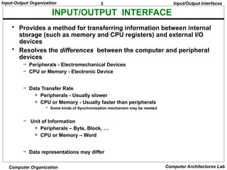
I/O BUS AND INTERFACE MODULES
Each peripheral has an interface module associated with it
Interface
- Decodes the device address (device code)
- Decodes the commands (operation)
- Provides signals for the peripheral controller
- Synchronizes the data flow and supervises
the transfer rate between peripheral and CPU or Memory
Typical I/O instruction
(Command)
Op. code Device address Function code
Input/Output Interfaces
Processor
Interface
Keyboard
and
display
terminal
Magnetic
tape
Printer
Interface Interface Interface
Data
Address
Control
Magnetic
disk
I/O bus
5.
5
Input-Output Organization
Computer OrganizationComputer Architectures Lab
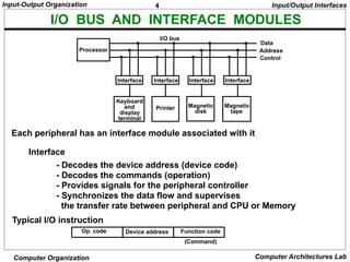
I/O BUS AND MEMORY BUS
•MEMORY BUS is for information transfers between CPU and the
MM
* I/O BUS is for information transfers between CPU
and I/O devices through their I/O interface
Functions of Buses
Input/Output Interfaces
6.
6
Input-Output Organization
Computer OrganizationComputer Architectures Lab
I/O INTERFACE
- Information in each port can be assigned a meaning
depending on the mode of operation of the I/O device
→ Port A = Data; Port B = Command; Port C = Status
- CPU initializes(loads) each port by transferring a byte to the Control Register
→ Allows CPU can define the mode of operation of each port
→ Programmable Port: By changing the bits in the control register, it is
possible to change the interface characteristics
CS RS1 RS0 Register selected
0 x x None - data bus in high-impedence
1 0 0 Port A register
1 0 1 Port B register
1 1 0 Control register
1 1 1 Status register
Programmable Interface
Input/Output Interfaces
Chip select
Register select
Register select
I/O read
I/O write
CS
RS1
RS0
RD
WR
Timing
and
Control
Bus
buffers
Bidirectional
data bus
Port A
register
Port B
register
Control
register
Status
register
I/O data
I/O data
Control
Status
Internal
bus
CPU I/O
Device
7.
7
Input-Output Organization
Computer OrganizationComputer Architectures Lab
ASYNCHRONOUS DATA TRANSFER
Synchronous - All devices derive the timing
information from common clock line
Asynchronous - No common clock
Asynchronous data transfer between two independent units requires that
control signals be transmitted between the communicating units to
indicate the time at which data is being transmitted
Strobe pulse
- A strobe pulse is supplied by one unit to indicate
the other unit when the transfer has to occur
Handshaking
- A control signal is accompanied with each data
being transmitted to indicate the presence of data
- The receiving unit responds with another control
signal to acknowledge receipt of the data
Synchronous and Asynchronous Operations
Asynchronous Data Transfer
Two Asynchronous Data Transfer Methods
Asynchronous Data Transfer
8.
8
Input-Output Organization
Computer OrganizationComputer Architectures Lab
* Employs a single control line to time each transfer
* The strobe may be activated by either the source or
the destination unit
STROBE CONTROL
Source
unit
Destination
unit
Data bus
Strobe
Data
Strobe
Valid data
Block Diagram
Timing Diagram
Source-Initiated Strobe
for Data Transfer
Source
unit
Destination
unit
Data bus
Strobe
Data
Strobe
Valid data
Block Diagram
Asynchronous Data Transfer
Destination-Initiated Strobe
for Data Transfer
Timing Diagram
9.
9
Input-Output Organization
Computer OrganizationComputer Architectures Lab
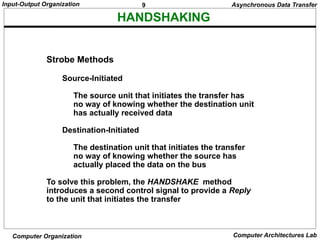
HANDSHAKING
Strobe Methods
Source-Initiated
The source unit that initiates the transfer has
no way of knowing whether the destination unit
has actually received data
Destination-Initiated
The destination unit that initiates the transfer
no way of knowing whether the source has
actually placed the data on the bus
To solve this problem, the HANDSHAKE method
introduces a second control signal to provide a Reply
to the unit that initiates the transfer
Asynchronous Data Transfer
10.
10
Input-Output Organization
Computer OrganizationComputer Architectures Lab
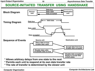
SOURCE-INITIATED TRANSFER USING HANDSHAKE
* Allows arbitrary delays from one state to the next
* Permits each unit to respond at its own data transfer rate
* The rate of transfer is determined by the slower unit
Block Diagram
Timing Diagram
Accept data from bus.
Enable data accepted
Disable data accepted.
Ready to accept data
(initial state).
Sequence of Events
Place data on bus.
Enable data valid.
Source unit Destination unit
Disable data valid.
Invalidate data on bus.
Source
unit
Destination
unit
Data bus
Data accepted
Data bus
Data valid
Valid data
Data valid
Data accepted
Asynchronous Data Transfer
11.
11
Input-Output Organization
Computer OrganizationComputer Architectures Lab
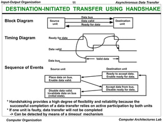
DESTINATION-INITIATED TRANSFER USING HANDSHAKE
* Handshaking provides a high degree of flexibility and reliability because the
successful completion of a data transfer relies on active participation by both units
* If one unit is faulty, data transfer will not be completed
-> Can be detected by means of a timeout mechanism
Block Diagram
Timing Diagram
Source
unit
Destination
unit
Data bus
Ready for data
Data valid
Sequence of Events
Place data on bus.
Enable data valid.
Source unit Destination unit
Ready to accept data.
Enable ready for data.
Disable data valid.
Invalidate data on bus
(initial state).
Accept data from bus.
Disable ready for data.
Ready for data
Data valid
Data bus
Valid data
Asynchronous Data Transfer
12.
12
Input-Output Organization
Computer OrganizationComputer Architectures Lab
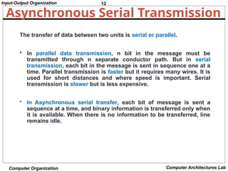
Asynchronous Serial Transmission
The transfer of data between two units is serial or parallel.
• In parallel data transmission, n bit in the message must be
transmitted through n separate conductor path. But in serial
transmission, each bit in the message is sent in sequence one at a
time. Parallel transmission is faster but it requires many wires. It is
used for short distances and where speed is important. Serial
transmission is slower but is less expensive.
• In Asynchronous serial transfer, each bit of message is sent a
sequence at a time, and binary information is transferred only when
it is available. When there is no information to be transferred, line
remains idle.
13.
13
Input-Output Organization
Computer OrganizationComputer Architectures Lab
Asynchronous Serial Transmission
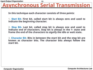
In this technique each character consists of three points:
1. Start Bit- First bit, called start bit is always zero and used to
indicate the beginning character.
2. Stop Bit- Last bit, called stop bit is always one and used to
indicate end of characters. Stop bit is always in the 1- state and
frame the end of the characters to signify the idle or wait state.
3. Character Bit- Bits in between the start bit and the stop bit are
known as character bits. The character bits always follow the
start bit.
14.
14
Input-Output Organization
Computer OrganizationComputer Architectures Lab
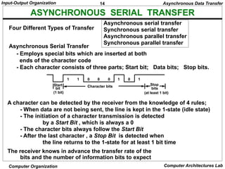
ASYNCHRONOUS SERIAL TRANSFER
Asynchronous serial transfer
Synchronous serial transfer
Asynchronous parallel transfer
Synchronous parallel transfer
- Employs special bits which are inserted at both
ends of the character code
- Each character consists of three parts; Start bit; Data bits; Stop bits.
A character can be detected by the receiver from the knowledge of 4 rules;
- When data are not being sent, the line is kept in the 1-state (idle state)
- The initiation of a character transmission is detected
by a Start Bit , which is always a 0
- The character bits always follow the Start Bit
- After the last character , a Stop Bit is detected when
the line returns to the 1-state for at least 1 bit time
The receiver knows in advance the transfer rate of the
bits and the number of information bits to expect
Four Different Types of Transfer
Asynchronous Serial Transfer
Start
bit
(1 bit)
Stop
bits
Character bits
1 1 0 0 0 1 0 1
(at least 1 bit)
Asynchronous Data Transfer
15.
15
Input-Output Organization
Computer OrganizationComputer Architectures Lab
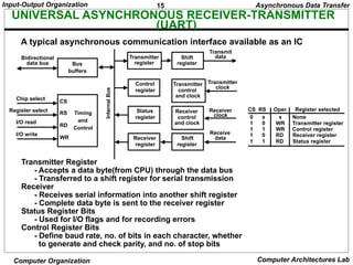
UNIVERSAL ASYNCHRONOUS RECEIVER-TRANSMITTER
(UART)
A typical asynchronous communication interface available as an IC
Transmitter Register
- Accepts a data byte(from CPU) through the data bus
- Transferred to a shift register for serial transmission
Receiver
- Receives serial information into another shift register
- Complete data byte is sent to the receiver register
Status Register Bits
- Used for I/O flags and for recording errors
Control Register Bits
- Define baud rate, no. of bits in each character, whether
to generate and check parity, and no. of stop bits
Chip select
Register select
I/O read
I/O write
CS
RS
RD
WR
Timing
and
Control
Bus
buffers
Bidirectional
data bus
Transmitter
register
Control
register
Status
register
Receiver
register
Shift
register
Transmitter
control
and clock
Receiver
control
and clock
Shift
register
Transmit
data
Transmitter
clock
Receiver
clock
Receive
data
Asynchronous Data Transfer
CS RS Oper. Register selected
0 x x None
1 0 WR Transmitter register
1 1 WR Control register
1 0 RD Receiver register
1 1 RD Status register
Internal
Bus
16.
16
Input-Output Organization
Computer OrganizationComputer Architectures Lab
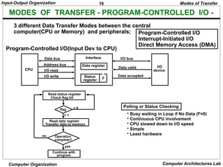
MODES OF TRANSFER - PROGRAM-CONTROLLED I/O -
3 different Data Transfer Modes between the central
computer(CPU or Memory) and peripherals; Program-Controlled I/O
Interrupt-Initiated I/O
Direct Memory Access (DMA)
Program-Controlled I/O(Input Dev to CPU)
Modes of Transfer
Polling or Status Checking
• Busy waiting in Loop if No Data (F=0)
• Continuous CPU involvement
• CPU slowed down to I/O speed
• Simple
• Least hardware
Read status register
Check flag bit
flag
Read data register
Transfer data to memory
Operation
complete?
Continue with
program
= 0
= 1
yes
no
CPU
Data bus
Address bus
I/O read
I/O write
Interface
Data register
Status
register F
I/O bus
Data valid
Data accepted
I/O
device
17.
17
Input-Output Organization
Computer OrganizationComputer Architectures Lab
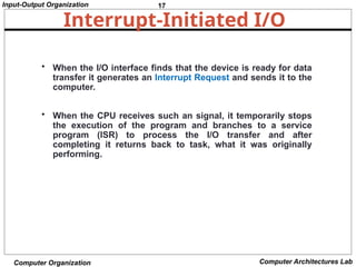
Interrupt-Initiated I/O
• When the I/O interface finds that the device is ready for data
transfer it generates an Interrupt Request and sends it to the
computer.
• When the CPU receives such an signal, it temporarily stops
the execution of the program and branches to a service
program (ISR) to process the I/O transfer and after
completing it returns back to task, what it was originally
performing.
19
Input-Output Organization
Computer OrganizationComputer Architectures Lab
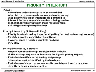
PRIORITY INTERRUPT
Priority Interrupt by Software(Polling)
- Priority is established by the order of polling the devices(interrupt sources)
- Flexible since it is established by software
- Low cost since it needs a very little hardware
- Very slow
Priority Interrupt by Hardware
- Require a priority interrupt manager which accepts
all the interrupt requests to determine the highest priority request
- Fast since identification of the highest priority
interrupt request is identified by the hardware
- Fast since each interrupt source has its own interrupt vector to access
directly to its own service routine
Priority
- Determines which interrupt is to be served first
when two or more requests are made simultaneously
- Also determines which interrupts are permitted to
interrupt the computer while another is being serviced
- Higher priority interrupts can make requests while
servicing a lower priority interrupt
Priority Interrupt
20.
20
Input-Output Organization
Computer OrganizationComputer Architectures Lab
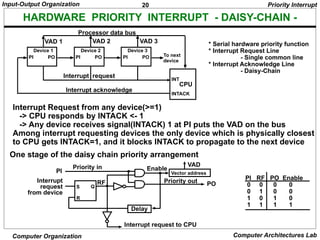
HARDWARE PRIORITY INTERRUPT - DAISY-CHAIN -
One stage of the daisy chain priority arrangement
PI RF PO Enable
0 0 0 0
0 1 0 0
1 0 1 0
1 1 1 1
Interrupt Request from any device(>=1)
-> CPU responds by INTACK <- 1
-> Any device receives signal(INTACK) 1 at PI puts the VAD on the bus
Among interrupt requesting devices the only device which is physically closest
to CPU gets INTACK=1, and it blocks INTACK to propagate to the next device
Priority Interrupt
Device 1
PI PO
Device 2
PI PO
Device 3
PI PO
INT
INTACK
Interrupt request
Interrupt acknowledge
To next
device
CPU
VAD 1 VAD 2 VAD 3
Processor data bus
* Serial hardware priority function
* Interrupt Request Line
- Single common line
* Interrupt Acknowledge Line
- Daisy-Chain
S
R
Q
Interrupt
request
from device
PI
Priority in
RF
Delay
Vector address
VAD
PO
Priority out
Interrupt request to CPU
Enable
21.
21
Input-Output Organization
Computer OrganizationComputer Architectures Lab
PARALLEL PRIORITY INTERRUPT
IEN: Set or Clear by instructions ION or IOF
IST: Represents an unmasked interrupt has occurred. INTACK enables
tristate Bus Buffer to load VAD generated by the Priority Logic
Interrupt Register:
- Each bit is associated with an Interrupt Request from
different Interrupt Source - different priority level
- Each bit can be cleared by a program instruction
Mask Register:
- Mask Register is associated with Interrupt Register
- Each bit can be set or cleared by an Instruction
Priority Interrupt
Mask
register
INTACK
from CPU
Priority
encoder
I0
I1
I 2
I 3
0
1
2
3
y
x
IST
IEN
0
1
2
3
0
0
0
0
0
0
Disk
Printer
Reader
Keyboard
Interrupt register
Enable
Interrupt
to CPU
VAD
to CPU
Bus
Buffer
22.
22
Input-Output Organization
Computer OrganizationComputer Architectures Lab
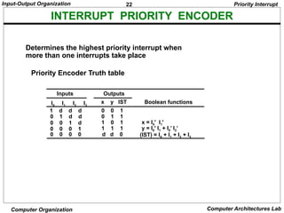
INTERRUPT PRIORITY ENCODER
Determines the highest priority interrupt when
more than one interrupts take place
Priority Encoder Truth table
1 d d d
0 1 d d
0 0 1 d
0 0 0 1
0 0 0 0
I0 I1 I2 I3
0 0 1
0 1 1
1 0 1
1 1 1
d d 0
x y IST
x = I0' I1'
y = I0' I1 + I0’ I2’
(IST) = I0 + I1 + I2 + I3
Inputs Outputs
Boolean functions
Priority Interrupt
23.
23
Input-Output Organization
Computer OrganizationComputer Architectures Lab
At the end of each Instruction cycle
- CPU checks IEN and IST
- If IEN IST = 1, CPU -> Interrupt Cycle
INTERRUPT CYCLE
SP SP - 1 Decrement stack pointer
M[SP] PC Push PC into stack
INTACK 1 Enable interrupt acknowledge
PC VAD Transfer vector address to PC
IEN 0 Disable further interrupts
Go To Fetch to execute the first instruction
in the interrupt service routine
Priority Interrupt
24.
24
Input-Output Organization
Computer OrganizationComputer Architectures Lab
INTERRUPT SERVICE ROUTINE
Initial and Final Operations
Each interrupt service routine must have an initial and final set of
operations for controlling the registers in the hardware interrupt system
Initial Sequence
[1] Clear lower level Mask reg. bits
[2] IST <- 0
[3] Save contents of CPU registers
[4] IEN <- 1
[5] Go to Interrupt Service Routine
Final Sequence
[1] IEN <- 0
[2] Restore CPU registers
[3] Clear the bit in the Interrupt Reg
[4] Set lower level Mask reg. bits
[5] Restore return address, IEN <- 1
Priority Interrupt
address Memory
JMP PTR
JMP RDR
JMP KBD
JMP DISK
0
1
2
3
I/O service programs
Program to service
magnetic disk
Program to service
line printer
Program to service
character reader
Program to service
keyboard
DISK
PTR
RDR
KBD
255
256
750
256
750
Stack
Main program
current instr.
749
KBD
interrupt
2
VAD=00000011 3
4
Disk
interrupt
5
6
7
8
9 10
11
1
25.
25
Input-Output Organization
Computer OrganizationComputer Architectures Lab
DIRECT MEMORY ACCESS
High-impedence
(disabled)
when BG is
enabled
CPU bus signals for DMA transfer
Block diagram of DMA controller
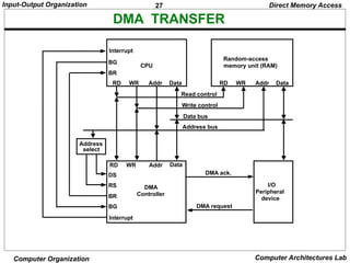
* Block of data transfer from high speed devices, Drum, Disk, Tape
* DMA controller - Interface which allows I/O transfer directly between
Memory and Device, freeing CPU for other tasks
* CPU initializes DMA Controller by sending memory
address and the block size(number of words)
Address bus
Data bus
Read
Write
ABUS
DBUS
RD
WR
Bus request
Bus granted
BR
BG
CPU
Address bus
Data bus
DMA select
Register select
Read
Write
Bus request
Bus grant
Interrupt
DS
RS
RD
WR
BR
BG
Interrupt
Data bus
buffers
Address bus
buffers
Address register
Word count register
Control register
DMA request
DMA acknowledge to I/O device
Control
logic
Direct Memory Access
Internal
Bus
26.
26
Input-Output Organization
Computer OrganizationComputer Architectures Lab
DMA I/O OPERATION
Starting an I/O
- CPU executes instruction to
Load Memory Address Register
Load Word Counter
Load Function(Read or Write) to be performed
Issue a GO command
Upon receiving a GO Command DMA performs I/O
operation as follows independently from CPU
Input
[1] Input Device <- R (Read control signal)
[2] Buffer(DMA Controller) <- Input Byte; and
assembles the byte into a word until word is full
[4] M <- memory address, W(Write control signal)
[5] Address Reg <- Address Reg +1; WC(Word Counter) <- WC - 1
[6] If WC = 0, then Interrupt to acknowledge done, else go to [1]
Output
[1] M <- M Address, R
M Address R <- M Address R + 1, WC <- WC - 1
[2] Disassemble the word
[3] Buffer <- One byte; Output Device <- W, for all disassembled bytes
[4] If WC = 0, then Interrupt to acknowledge done, else go to [1]
Direct Memory Access
27.
27
Input-Output Organization
Computer OrganizationComputer Architectures Lab
DMA TRANSFER
BG
BR
CPU
RD WR Addr Data
Interrupt
Random-access
memory unit (RAM)
RD WR Addr Data
BR
BG
RD WR Addr Data
Interrupt
DS
RS DMA
Controller
I/O
Peripheral
device
DMA request
DMA ack.
Read control
Write control
Data bus
Address bus
Address
select
Direct Memory Access
28.
28
Input-Output Organization
Computer OrganizationComputer Architectures Lab
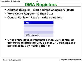
DMA Registers
• Address Register – start address of memory (1000)
• Word Count Register (10 then 9 …)
• Control Register (Read or Write operation)
• Once entire data is transferred then DMA controller
generates Interrupt to CPU so that CPU can take the
control of Bus by making BG = 0
1000
1010 (10 words)
29.
29
Input-Output Organization
Computer OrganizationComputer Architectures Lab
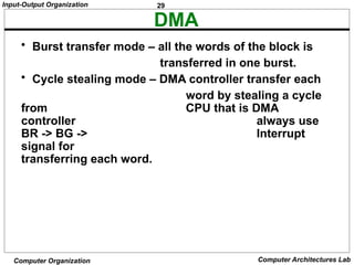
DMA
• Burst transfer mode – all the words of the block is
transferred in one burst.
• Cycle stealing mode – DMA controller transfer each
word by stealing a cycle
from CPU that is DMA
controller always use
BR -> BG -> Interrupt
signal for
transferring each word.
30.
30
Input-Output Organization
Computer OrganizationComputer Architectures Lab
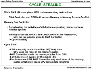
CYCLE STEALING
While DMA I/O takes place, CPU is also executing instructions
DMA Controller and CPU both access Memory -> Memory Access Conflict
Memory Bus Controller
- Coordinating the activities of all devices requesting memory access
- Priority System
Memory accesses by CPU and DMA Controller are interwoven,
with the top priority given to DMA Controller
-> Cycle Stealing
Cycle Steal
- CPU is usually much faster than I/O(DMA), thus
CPU uses the most of the memory cycles
- DMA Controller steals the memory cycles from CPU
- For those stolen cycles, CPU remains idle
- For those slow CPU, DMA Controller may steal most of the memory
cycles which may cause CPU remain idle long time
Direct Memory Access
31.
31
Input-Output Organization
Computer OrganizationComputer Architectures Lab
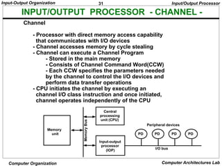
INPUT/OUTPUT PROCESSOR - CHANNEL -
Channel
- Processor with direct memory access capability
that communicates with I/O devices
- Channel accesses memory by cycle stealing
- Channel can execute a Channel Program
- Stored in the main memory
- Consists of Channel Command Word(CCW)
- Each CCW specifies the parameters needed
by the channel to control the I/O devices and
perform data transfer operations
- CPU initiates the channel by executing an
channel I/O class instruction and once initiated,
channel operates independently of the CPU
Input/Output Processor
PD PD PD PD
Peripheral devices
I/O bus
Input-output
processor
(IOP)
Central
processing
unit (CPU)
Memory
unit
Memory
Bus
32.
32
Input-Output Organization
Computer OrganizationComputer Architectures Lab
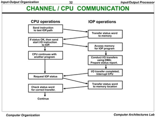
CHANNEL / CPU COMMUNICATION
Send instruction
to test IOP.path
If status OK, then send
start I/O instruction
to IOP.
CPU continues with
another program
Transfer status word
to memory
Access memory
for IOP program
Conduct I/O transfers
using DMA;
Prepare status report.
I/O transfer completed;
Interrupt CPU
Request IOP status
Transfer status word
to memory location
Check status word
for correct transfer.
Continue
CPU operations IOP operations
Input/Output Processor
33.
33
Input-Output Organization
Computer OrganizationComputer Architectures Lab
Serial Communication
Data communication processor
Modem
Modes Of Transmission (Data Transfer Modes)
– Simplex
– Full Duplex
– Half Duplex
Protocols:
Character-Oriented Protocol
Bit-Oriented Protocol
34.
34
Input-Output Organization
Computer OrganizationComputer Architectures Lab
Serial Communication
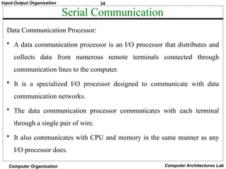
Data Communication Processor:
• A data communication processor is an I/O processor that distributes and
collects data from numerous remote terminals connected through
communication lines to the computer.
• It is a specialized I/O processor designed to communicate with data
communication networks.
• The data communication processor communicates with each terminal
through a single pair of wire.
• It also communicates with CPU and memory in the same manner as any
I/O processor does.
35.
35
Input-Output Organization
Computer OrganizationComputer Architectures Lab
Serial Communication
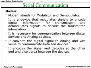
Modem:
• Modem stands for Modulator and Demodulator.
• It is a device that modulates signals to encode
digital information for transmission and
demodulates signals to decode the transmitted
information.
• It is necessary for communication between digital
devices and Analog devices.
• It converts the digital signal to Analog and vice
versa to communicate between devices.
• It encodes the signal and decodes at the other
end and vice versa between the devices.
36.
36
Input-Output Organization
Computer OrganizationComputer Architectures Lab
Serial Communication
Modes Of Transmission:
Data can be transmitted between 2 points by three
different modes:
• Simplex:
A simplex line carries information in one direction only. In
this mode receiver cannot communicate with the sender to
indicate the occurrence of errors that means only sender
can send data but receiver cannot. For example: Radio and
Television Broadcasting.
37.
37
Input-Output Organization
Computer OrganizationComputer Architectures Lab
Modes Of Transmission
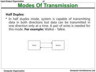
Half Duplex:
• In half duplex mode, system is capable of transmitting
data in both directions but data can be transmitted in
one direction only at a time. A pair of wires is needed for
this mode. For example: Walkie - Talkie.
38.
38
Input-Output Organization
Computer OrganizationComputer Architectures Lab
Modes Of Transmission
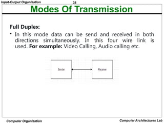
Full Duplex:
• In this mode data can be send and received in both
directions simultaneously. In this four wire link is
used. For example: Video Calling, Audio calling etc.
39.
39
Input-Output Organization
Computer OrganizationComputer Architectures Lab
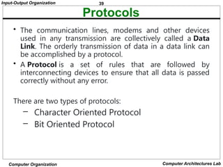
Protocols
• The communication lines, modems and other devices
used in any transmission are collectively called a Data
Link. The orderly transmission of data in a data link can
be accomplished by a protocol.
• A Protocol is a set of rules that are followed by
interconnecting devices to ensure that all data is passed
correctly without any error.
There are two types of protocols:
– Character Oriented Protocol
– Bit Oriented Protocol
40.
40
Input-Output Organization
Computer OrganizationComputer Architectures Lab
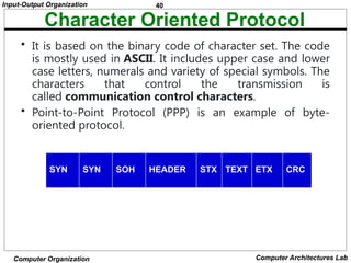
Character Oriented Protocol
• It is based on the binary code of character set. The code
is mostly used in ASCII. It includes upper case and lower
case letters, numerals and variety of special symbols. The
characters that control the transmission is
called communication control characters.
• Point-to-Point Protocol (PPP) is an example of byte-
oriented protocol.
SYN SYN SOH HEADER STX TEXT ETX CRC
43
Input-Output Organization
Computer OrganizationComputer Architectures Lab
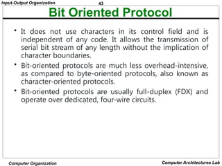
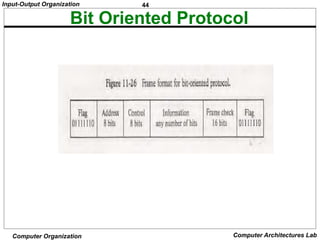
Bit Oriented Protocol
• It does not use characters in its control field and is
independent of any code. It allows the transmission of
serial bit stream of any length without the implication of
character boundaries.
• Bit-oriented protocols are much less overhead-intensive,
as compared to byte-oriented protocols, also known as
character-oriented protocols.
• Bit-oriented protocols are usually full-duplex (FDX) and
operate over dedicated, four-wire circuits.


![23
Input-Output Organization
Computer Organization Computer Architectures Lab
At the end of each Instruction cycle
- CPU checks IEN and IST
- If IEN IST = 1, CPU -> Interrupt Cycle
INTERRUPT CYCLE
SP SP - 1 Decrement stack pointer
M[SP] PC Push PC into stack
INTACK 1 Enable interrupt acknowledge
PC VAD Transfer vector address to PC
IEN 0 Disable further interrupts
Go To Fetch to execute the first instruction
in the interrupt service routine
Priority Interrupt](https://image.slidesharecdn.com/coaunit-4notes-250305033342-5f7f1dd0/85/COA_UNIT-4_NOTES-pptxtdvyunbuubbubufjfgn-23-320.jpg)
![24
Input-Output Organization
Computer Organization Computer Architectures Lab
INTERRUPT SERVICE ROUTINE
Initial and Final Operations
Each interrupt service routine must have an initial and final set of
operations for controlling the registers in the hardware interrupt system
Initial Sequence
[1] Clear lower level Mask reg. bits
[2] IST <- 0
[3] Save contents of CPU registers
[4] IEN <- 1
[5] Go to Interrupt Service Routine
Final Sequence
[1] IEN <- 0
[2] Restore CPU registers
[3] Clear the bit in the Interrupt Reg
[4] Set lower level Mask reg. bits
[5] Restore return address, IEN <- 1
Priority Interrupt
address Memory
JMP PTR
JMP RDR
JMP KBD
JMP DISK
0
1
2
3
I/O service programs
Program to service
magnetic disk
Program to service
line printer
Program to service
character reader
Program to service
keyboard
DISK
PTR
RDR
KBD
255
256
750
256
750
Stack
Main program
current instr.
749
KBD
interrupt
2
VAD=00000011 3
4
Disk
interrupt
5
6
7
8
9 10
11
1](https://image.slidesharecdn.com/coaunit-4notes-250305033342-5f7f1dd0/85/COA_UNIT-4_NOTES-pptxtdvyunbuubbubufjfgn-24-320.jpg)

![26
Input-Output Organization
Computer Organization Computer Architectures Lab
DMA I/O OPERATION
Starting an I/O
- CPU executes instruction to
Load Memory Address Register
Load Word Counter
Load Function(Read or Write) to be performed
Issue a GO command
Upon receiving a GO Command DMA performs I/O
operation as follows independently from CPU
Input
[1] Input Device <- R (Read control signal)
[2] Buffer(DMA Controller) <- Input Byte; and
assembles the byte into a word until word is full
[4] M <- memory address, W(Write control signal)
[5] Address Reg <- Address Reg +1; WC(Word Counter) <- WC - 1
[6] If WC = 0, then Interrupt to acknowledge done, else go to [1]
Output
[1] M <- M Address, R
M Address R <- M Address R + 1, WC <- WC - 1
[2] Disassemble the word
[3] Buffer <- One byte; Output Device <- W, for all disassembled bytes
[4] If WC = 0, then Interrupt to acknowledge done, else go to [1]
Direct Memory Access](https://image.slidesharecdn.com/coaunit-4notes-250305033342-5f7f1dd0/85/COA_UNIT-4_NOTES-pptxtdvyunbuubbubufjfgn-26-320.jpg)


![[DSC Europe 25] Gordana Milutinovic Dumbelovic - From Insight to Oversight: A...](https://cdn.slidesharecdn.com/ss_thumbnails/t7dkjsfxqwwzceropjv4-gordana-milutinovicdumbelovic-from-insight-to-oversight-ai-driven-power-bi-moni-260119121559-9e0bf11b-thumbnail.jpg?width=640&height=640&fit=bounds)


![[DSC Europe 25] Jovan Sumarac - Real-World Applications of Computer Vision in...](https://cdn.slidesharecdn.com/ss_thumbnails/fiksms22smcpopvvld03-jovan-sumarac-real-life-applications-of-computer-vision-in-automotive-systems-260120105855-de622abb-thumbnail.jpg?width=640&height=640&fit=bounds)
![[DSC Europe 25] Bojan Djuricic - Predictive Design Process.pdf](https://cdn.slidesharecdn.com/ss_thumbnails/5awdrbedqdek3gqu2ezy-4-the-predictive-design-bojan-djuricic-260120105856-6c399e9b-thumbnail.jpg?width=640&height=640&fit=bounds)

![[DSC Europe 25] Bojan Banjac - AI is always right when it comes to the matter...](https://cdn.slidesharecdn.com/ss_thumbnails/syoxtqierpydwxm5srcb-4-bojan-banjac-ai-is-always-right-when-it-comes-to-the-matters-of-taste-260119101519-694ee7d7-thumbnail.jpg?width=640&height=640&fit=bounds)

![[DSC Europe 25] Tamas Srancsik - How To Teach Your AI Football? An Argument f...](https://cdn.slidesharecdn.com/ss_thumbnails/bcjh1m9xtbosv20ucftb-tamas-srancsik-how-to-teach-your-ai-football-260121115910-08b53e9e-thumbnail.jpg?width=640&height=640&fit=bounds)


![[DSC Europe 25] Srdj Stanisic - Local and Private AI in UX.pdf](https://cdn.slidesharecdn.com/ss_thumbnails/vwmetykqmztgmokmmkfa-3-srdjan-stanisic-local-and-small-ai-in-ux-260120105855-55a31869-thumbnail.jpg?width=640&height=640&fit=bounds)


