The document discusses input-output (I/O) interfaces in computers. It provides details on:
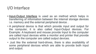
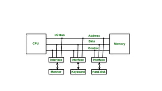
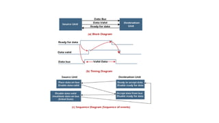
1. I/O interfaces act as a hardware circuit between the CPU and I/O devices to synchronize data transfer.
2. There are differences between peripheral devices and CPUs in operation, data formats, and speeds that require special hardware (I/O interfaces) to resolve.
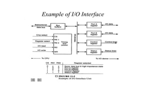
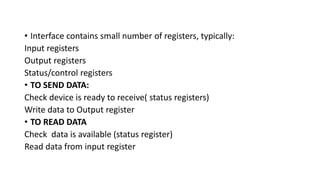
3. I/O interfaces contain registers to buffer input and output data and status information during transfers between CPUs and peripheral devices like keyboards, printers, and monitors.
1. I/O Interface
It is a hardware circuit used between CPU and I/O devices to super wise
and synchronize all input and output transfer.
2. I/O Interface
• Input-Output Interface is used as an method which helps in
transferring of information between the internal storage devices
i.e. memory and the external peripheral device .
• A peripheral device is that which provide input and output for
the computer, it is also called Input-Output devices. For
Example: A keyboard and mouse provide Input to the computer
are called input devices while a monitor and printer that provide
output to the computer are called output devices.
• Just like the external hard-drives, there is also availability of
some peripheral devices which are able to provide both input
and output.
3.
4. • In micro-computer base system, the only purpose of peripheral
devices is just to provide special communication links for the
interfacing them with the CPU. To resolve the differences
between peripheral devices and CPU, there is a special need
for communication links.
5. The major differences are as follows:
1.The nature of peripheral devices is electromagnetic and
electro-mechanical. The nature of the CPU is electronic. There
is a lot of difference in the mode of operation of both peripheral
devices and CPU.
2.There is also a synchronization mechanism because the data
transfer rate of peripheral devices are slow than CPU.
3.In peripheral devices, data code and formats are differ from the
format in the CPU and memory.
4.The operating mode of peripheral devices are different and
each may be controlled so as not to disturb the operation of
other peripheral devices connected to CPU.
6. There is a special need of the additional hardware to resolve the differences
between CPU and peripheral devices to supervise and synchronize all input
and output devices.
• Functions of Input-Output Interface:
1.It is used to synchronize the operating speed of CPU with respect to input-
output devices.
2.It selects the input-output device which is appropriate for the interpretation
of the input-output device.
3.It is capable of providing signals like control and timing signals.
4.In this data buffering can be possible through data bus.
5.There are various error detectors.
6.It converts serial data into parallel data and vice-versa.
7.It also convert digital data into analog signal and vice-versa.
7.
8. • Interface contains small number of registers, typically:
Input registers
Output registers
Status/control registers
• TO SEND DATA:
Check device is ready to receive( status registers)
Write data to Output register
• TO READ DATA
Check data is available (status register)
Read data from input register
9. I/O commands
I/O commands are the instructions given by the CPU to I/O interface or I/O
devices to perform the specific operations.
Types of I/O commands
Control Commands: This command is given by CPU to I/O device to activate it
& tell it what to do( Read/Write)
Status Command: This command is given by CPU to check status of I/O
devices.
Data Input Command: This command is given by CPU to read any data from
input devices.
Data Output Command: This command is given by CPU to write any data to
output device.
10. • In isolated I/O , the address and data bus are common, but control
bus are different. For memory, it has memory read and write control
lines. For I/O device it has a separate I/0 Read and I/O write control
lines
ISOLATED I/O
11. Memory Mapped I/O
• Address data and control bus are common for memory & I/O devices.
12. Asynchronous Data Transfer in Computer
The internal operations in an individual unit of a digital system are
synchronized using clock pulse. It means clock pulse is given to all
registers within a unit. And all data transfer among internal registers
occurs simultaneously during the occurrence of the clock pulse. Now,
suppose any two units of a digital system are designed independently,
such as CPU and I/O interface.
Synchronous: If the registers in the I/O interface share a common
clock with CPU registers, then transfer between the two units is said to
be synchronous.
Asynchronous: The internal timing in each unit is independent of
each other, so each uses its private clock for its internal registers. In
this case, the two units are said to be asynchronous to each other,
and if data transfer occurs between them, this data transfer is
called Asynchronous Data Transfer.
13. In the Asynchronous Data Transfer between two independent
units requires that control signals be transmitted between the
communicating units so that the time can be indicated at which
they send data. These two methods can achieve this
asynchronous way of data transfer:
• Strobe control: A strobe pulse is supplied by one unit to
indicate to the other unit when the transfer has to occur.
• Handshaking: This method is commonly used to accompany
each data item being transferred with a control signal that
indicates data in the bus. The unit receiving the data item
responds with another signal to acknowledge receipt of the
data.
14. 1. Strobe Control Method
• The Strobe Control method of asynchronous data transfer
employs a single control line to time each transfer. This control
line is also known as a strobe, and it may be achieved either by
source or destination, depending on which initiate the transfer.
15. • Source initiated strobe: In the below block diagram, you can
see that strobe is initiated by source, and as shown in the timing
diagram, the source unit first places the data on the data bus.
16. • After a brief delay to ensure that the data resolve to a stable
value, the source activates a strobe pulse. The information on
the data bus and strobe control signal remains in the active state
for a sufficient time to allow the destination unit to receive the
data.
The destination unit uses a falling edge of strobe control to
transfer the contents of a data bus to one of its internal registers.
The source removes the data from the data bus after it disables
its strobe pulse. Thus, new valid data will be available only after
the strobe is enabled again.
In this case, the strobe may be a memory-write control signal
from the CPU to a memory unit. The CPU places the word on the
data bus and informs the memory unit, which is the destination.
17. • Destination initiated strobe: In the below block diagram, you
see that the strobe initiated by destination, and in the timing
diagram, the destination unit first activates the strobe pulse,
informing the source to provide the data.
18.
19. The source unit responds by placing the requested binary
information on the data bus. The data must be valid and remain
on the bus long enough for the destination unit to accept it.
The falling edge of the strobe pulse can use again to trigger a
destination register. The destination unit then disables the strobe.
Finally, and source removes the data from the data bus after a
determined time interval.
In this case, the strobe may be a memory read control from the
CPU to a memory unit. The CPU initiates the read operation to
inform the memory, which is a source unit, to place the selected
word into the data bus.
20. Handshaking Method
DISADVANTAGE OF STROB: The strobe method has the disadvantage that the source
unit that initiates the transfer has no way of knowing whether the destination has received
the data that was placed in the bus. Similarly, a destination unit that initiates the transfer has
no way of knowing whether the source unit has placed data on the bus.
So, this problem is solved by the handshaking method. The handshaking method introduces
a second control signal line that replays the unit that initiates the transfer.
In this method, one control line is in the same direction as the data flow in the bus from the
source to the destination. The source unit uses it to inform the destination unit whether there
are valid data in the bus.
The other control line is in the other direction from the destination to the source. This is
because the destination unit uses it to inform the source whether it can accept data. And in
it also, the sequence of control depends on the unit that initiates the transfer. So it means
the sequence of control depends on whether the transfer is initiated by source and
destination.
21. Source initiated handshaking: In the below block diagram, you can see
that two handshaking lines are "data valid", which is generated by the
source unit, and "data accepted", generated by the destination unit.
22. The timing diagram shows the timing relationship of the exchange of signals between the
two units. The source initiates a transfer by placing data on the bus and enabling its data
valid signal.
The destination unit then activates the data accepted signal after it accepts the data from
the bus.
The source unit then disables its valid data signal, which invalidates the data on the bus.
After this, the destination unit disables its data accepted signal, and the system goes into its
initial state. The source unit does not send the next data item until after the destination unit
shows readiness to accept new data by disabling the data accepted signal.
23. • Destination initiated handshaking: In the below block
diagram, you see that the two handshaking lines are "data
valid", generated by the source unit, and "ready for data"
generated by the destination unit.
Note that the name of signal data accepted generated by the
destination unit has been changed to ready for data to reflect its
new meaning.
24.
25. • The destination transfer is initiated, so the source unit does not
place data on the data bus until it receives a ready data signal
from the destination unit. After that, the handshaking process is
the same as that of the source initiated.