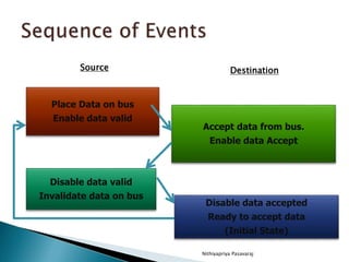
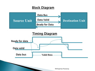
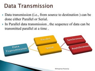
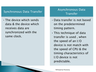
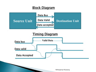
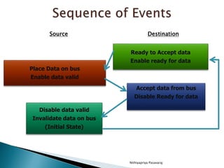
Nithiyapriya Pasavaraj
 Data transmission (i.e., from source to destination ) can be
done either Parallel or Serial.
 In Parallel data transmission , the sequence of data can be
transmitted parallel at a time .
Nithiyapriya Pasavaraj
Synchronous Data Transfer
• The device which sends
data & the device which
receives data are
synchronized with the
same clock.
Asynchronous Data
Transfer
• Data transfer is not based
on the predetermined
timing pattern.
• This technique of data
transfer is used , when
the speed of an I/O
device is not match with
the speed of CPU & the
timing characteristics of
I/O device is not
predictable.
 In a computer system , CPU & I/O interfaces
are designed independently of each other.
 When the internal timing in each unit is
independent from the other and the registers
in Interface & registers of CPU uses its own
private clock, Asynchronous data transfer can
be used to coordinate the speed & its timing
characteristics.
Nithiyapriya Pasavaraj
 The Asynchronous data transfer between two
independent units requires that control signals
transmitted between the communicating units ,
so that the time can be indicated at which they
send data.
 The Asynchronous way of data transfer can be
achieved by two methods.
 Strobe control
 Handshaking
Nithiyapriya Pasavaraj
 The strobe control method of asynchronous
data transfer employs a single control line to
time each transfer, which is known as strobe.
 It may be achieved either by source or
destination.
Nithiyapriya Pasavaraj
Source Unit Destination Unit
Data Bus
Strobe
Block Diagram
Timing Diagram
Valid Data
Data
Strobe
 The data bus carries the binary information from
source unit to the destination unit.
 The strobe is a single line that informs the destination
unit when a valid data word is available in the bus.
 The source unit first places the data on the bus.
 After a brief delay (to ensure that the data settle to a
steady value), the source activates the strobe pulse.
 The information of the data bus and the strobe signal
remain in the active state for sufficient time period to
allow the destination unit to receive the data.
 The source removes the data from the bus for a brief
period of time after it disables its strobe pulse.
Nithiyapriya Pasavaraj
Valid Data
Data
Strobe
Source Unit Destination Unit
Data Bus
Strobe
Block Diagram
Timing Diagram
 The destination unit activates hr strobe pulse
, informing the source to provide the data.
 The source unit responds by placing the
required binary information on the unit to
accept it.
 The data must be valid and remain in the bus
long enough for destination unit to accept it.
 The falling edge of strobe pulse can be used
again to trigger a destination register.
 The destination unit then disables the strobe.
 The source removes the data from the bus
after a predetermined time interval.
Nithiyapriya Pasavaraj
 The source unit that initiates the transfer has
no way of knowing whether the destination
unit has actually received the data item that
was placed in bus.
 The destination unit that initiates the transfer
has no way knowing whether the source unit
has actually placed the data on the bus.
Nithiyapriya Pasavaraj
 The Handshaking method solves the
problems raised in strobe method, by
introducing a second control signal that
provides a reply to the unit that initiates the
transfer.
 The data transfer can be occur as
◦ Source initiated Transfer
◦ Destination initiated Transfer
Nithiyapriya Pasavaraj
 The Two Handshaking lines generated from
the source are,
 Data Valid - Source to Destination to inform, whether
there are valid data in the bus.
 Data Accept -Destination to source to inform, whether
it can accept data.
Nithiyapriya Pasavaraj
Source Unit Destination Unit
Data Bus
Data Valid
Timing Diagram
Valid Data
Data bus
Data valid
Block Diagram
Data accepted
Data Accepted
Nithiyapriya Pasavaraj
Place Data on bus
Enable data valid
Accept data from bus.
Enable data Accept
Disable data valid
Invalidate data on bus
Disable data accepted
Ready to accept data
(Initial State)
Source Destination
The source unit initiates the transfer by placing the
data on the bus and enabling its data valid signal.
The data accepted signal is activated by the
destination unit after it accepts the data from the
bus.
The source unit then disable its data valid signal ,
which invalidates the data on the bus.
The destination unit disable its data accepted signal
and the system goes into its initial state.
Nithiyapriya Pasavaraj
The two handshaking lines in this scheme are
Data valid
Ready for data
The source unit in this case, does not place
data on the bus until after it receives the ready
for data signal from the destination unit.
Nithiyapriya Pasavaraj
Source Unit Destination Unit
Data Bus
Data Valid
Timing Diagram
Valid Data
Ready for data
Data valid
Block Diagram
Ready for Data
Data bus
Nithiyapriya Pasavaraj
Place Data on bus
Enable data valid
Ready to Accept data
Enable ready for data
Disable data valid
Invalidate data on bus
(Initial State)
Accept data from bus
Disable Ready for data
Source Destination
 The handshaking procedure follows the
same pattern as in source initiated except
the read for data signal has been converted
from data accepted in case of source
initiated.
Nithiyapriya Pasavaraj

Asynchronous data transfer

  • 1.
  • 2.
     Data transmission(i.e., from source to destination ) can be done either Parallel or Serial.  In Parallel data transmission , the sequence of data can be transmitted parallel at a time . Nithiyapriya Pasavaraj
  • 3.
    Nithiyapriya Pasavaraj Synchronous DataTransfer • The device which sends data & the device which receives data are synchronized with the same clock. Asynchronous Data Transfer • Data transfer is not based on the predetermined timing pattern. • This technique of data transfer is used , when the speed of an I/O device is not match with the speed of CPU & the timing characteristics of I/O device is not predictable.
  • 4.
     In acomputer system , CPU & I/O interfaces are designed independently of each other.  When the internal timing in each unit is independent from the other and the registers in Interface & registers of CPU uses its own private clock, Asynchronous data transfer can be used to coordinate the speed & its timing characteristics. Nithiyapriya Pasavaraj
  • 5.
     The Asynchronousdata transfer between two independent units requires that control signals transmitted between the communicating units , so that the time can be indicated at which they send data.  The Asynchronous way of data transfer can be achieved by two methods.  Strobe control  Handshaking Nithiyapriya Pasavaraj
  • 6.
     The strobecontrol method of asynchronous data transfer employs a single control line to time each transfer, which is known as strobe.  It may be achieved either by source or destination. Nithiyapriya Pasavaraj
  • 7.
    Nithiyapriya Pasavaraj Source UnitDestination Unit Data Bus Strobe Block Diagram Timing Diagram Valid Data Data Strobe
  • 8.
     The databus carries the binary information from source unit to the destination unit.  The strobe is a single line that informs the destination unit when a valid data word is available in the bus.  The source unit first places the data on the bus.  After a brief delay (to ensure that the data settle to a steady value), the source activates the strobe pulse.  The information of the data bus and the strobe signal remain in the active state for sufficient time period to allow the destination unit to receive the data.  The source removes the data from the bus for a brief period of time after it disables its strobe pulse. Nithiyapriya Pasavaraj
  • 9.
    Nithiyapriya Pasavaraj Valid Data Data Strobe SourceUnit Destination Unit Data Bus Strobe Block Diagram Timing Diagram
  • 10.
     The destinationunit activates hr strobe pulse , informing the source to provide the data.  The source unit responds by placing the required binary information on the unit to accept it.  The data must be valid and remain in the bus long enough for destination unit to accept it.  The falling edge of strobe pulse can be used again to trigger a destination register.  The destination unit then disables the strobe.  The source removes the data from the bus after a predetermined time interval. Nithiyapriya Pasavaraj
  • 11.
     The sourceunit that initiates the transfer has no way of knowing whether the destination unit has actually received the data item that was placed in bus.  The destination unit that initiates the transfer has no way knowing whether the source unit has actually placed the data on the bus. Nithiyapriya Pasavaraj
  • 12.
     The Handshakingmethod solves the problems raised in strobe method, by introducing a second control signal that provides a reply to the unit that initiates the transfer.  The data transfer can be occur as ◦ Source initiated Transfer ◦ Destination initiated Transfer Nithiyapriya Pasavaraj
  • 13.
     The TwoHandshaking lines generated from the source are,  Data Valid - Source to Destination to inform, whether there are valid data in the bus.  Data Accept -Destination to source to inform, whether it can accept data. Nithiyapriya Pasavaraj
  • 14.
    Nithiyapriya Pasavaraj Source UnitDestination Unit Data Bus Data Valid Timing Diagram Valid Data Data bus Data valid Block Diagram Data accepted Data Accepted
  • 15.
    Nithiyapriya Pasavaraj Place Dataon bus Enable data valid Accept data from bus. Enable data Accept Disable data valid Invalidate data on bus Disable data accepted Ready to accept data (Initial State) Source Destination
  • 16.
    The source unitinitiates the transfer by placing the data on the bus and enabling its data valid signal. The data accepted signal is activated by the destination unit after it accepts the data from the bus. The source unit then disable its data valid signal , which invalidates the data on the bus. The destination unit disable its data accepted signal and the system goes into its initial state. Nithiyapriya Pasavaraj
  • 17.
    The two handshakinglines in this scheme are Data valid Ready for data The source unit in this case, does not place data on the bus until after it receives the ready for data signal from the destination unit. Nithiyapriya Pasavaraj
  • 18.
    Nithiyapriya Pasavaraj Source UnitDestination Unit Data Bus Data Valid Timing Diagram Valid Data Ready for data Data valid Block Diagram Ready for Data Data bus
  • 19.
    Nithiyapriya Pasavaraj Place Dataon bus Enable data valid Ready to Accept data Enable ready for data Disable data valid Invalidate data on bus (Initial State) Accept data from bus Disable Ready for data Source Destination
  • 20.
     The handshakingprocedure follows the same pattern as in source initiated except the read for data signal has been converted from data accepted in case of source initiated. Nithiyapriya Pasavaraj