Downloaded 276 times

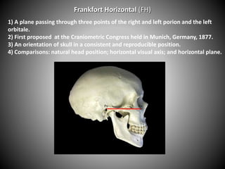
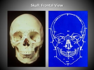
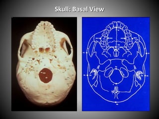
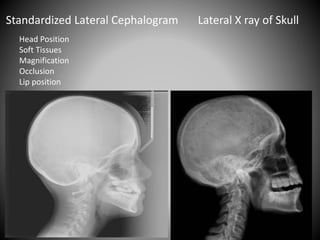

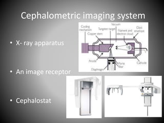
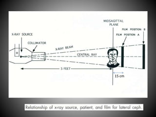


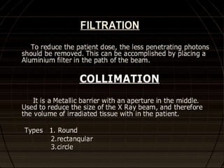
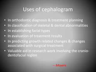
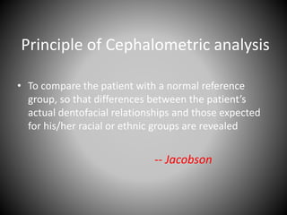
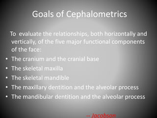
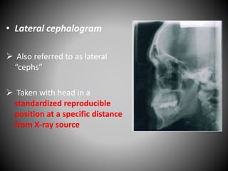
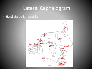
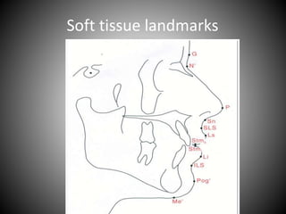
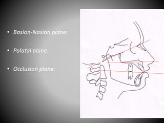
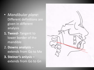
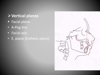

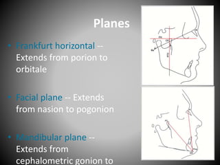
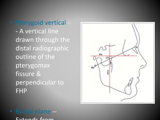
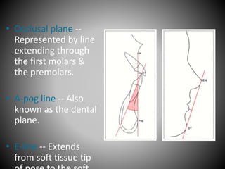
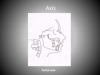

Cephalometrics involves taking X-ray measurements of the head and skull to analyze facial structure and dental relationships. Key aspects include: - Cephalometrics originated from measuring shadows of bony landmarks on X-ray images. - Standardized head positions and planes like the Frankfort Horizontal are used for reproducible measurements. - Analyses like Steiner and Downs involve measuring angles and distances between landmarks to assess skeletal and dental relationships compared to norms. - Measurements are used for orthodontic diagnosis, treatment planning, and evaluating outcomes.


![CTEV [ clubfoot] DR ARUN LAL ,DR MOHAMED ASHRAF travancore medical college k...](https://cdn.slidesharecdn.com/ss_thumbnails/ctevclubfootdrarunlaldrmohamedashraftravancoremedicalcollegekollamkeralaindia-260208063247-18fc466c-thumbnail.jpg?width=640&height=640&fit=bounds)


![ONFH[AVN HIP] -TRIPLE REGIME -A NOVAL SURGICAL CONCEPT .pptx](https://cdn.slidesharecdn.com/ss_thumbnails/onfhavnhip2026koaconcalicutdrgokuldevdrmashraf-260210064517-213ec005-thumbnail.jpg?width=640&height=640&fit=bounds)

