Downloaded 150 times


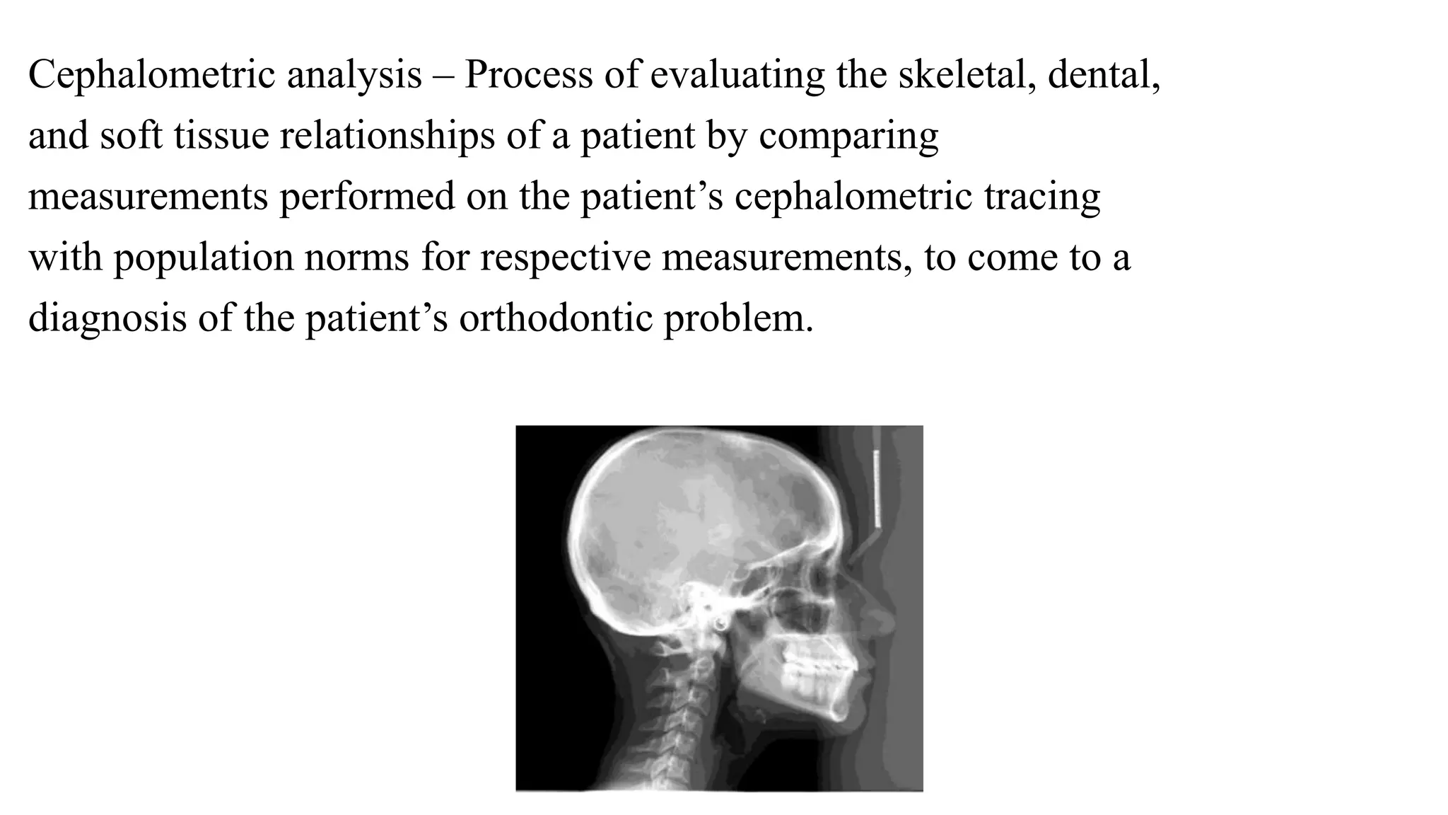


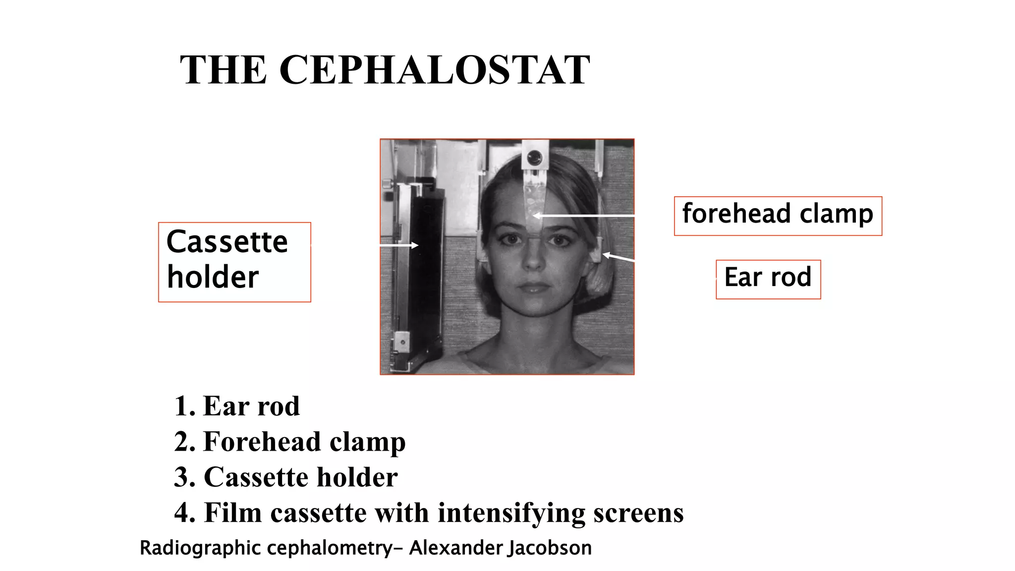


This document provides an overview of cephalometrics, which involves the scientific measurement of the head. It discusses the definition, history, techniques, landmarks, and analysis involved in cephalometric radiography and tracings. Some key points covered include: - Cephalometrics allows evaluation of skeletal, dental, and soft tissue relationships through standardized lateral head radiographs and tracings of cephalometric landmarks. - Broadbent introduced standardized cephalometric radiography techniques in the 1930s that are still used today. - Lateral and posterioanterior radiographs are taken using a cephalostat to maintain a fixed spatial relationship between the patient and x-ray source. - Tracings of radiographs


