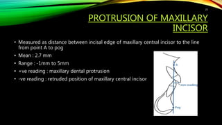
The document discusses hard tissue cephalometrics and various analytical methods for evaluating orthodontic conditions, including Downs, Steiner's, Tweed's, Ricketts, and McNamara analyses. It emphasizes the use of cephalometric analysis to assess skeletal, dental, and soft tissue relationships in patients for diagnosis and treatment planning. Key cephalometric landmarks and techniques for measurement are detailed to facilitate accurate evaluations.


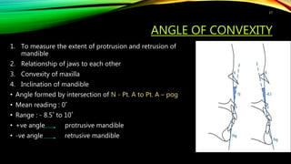
![DOWN’S ANALYSIS
• 1948
• Control material – 20 white subjects [age: 12-17 yrs] with equal no. of boys and
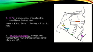
girls
• Reference plane : FRANKFORT HORIZONTAL PLANE {FH}
• Four basic facial types:
1. Retrognathic
2. Orthognathic
3. Prognathic
4. True prognathism
• Parameters of analysis :
skeletal and dental
Dental parameters
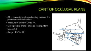
Cant of occlusal plane
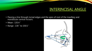
Interincisal angle
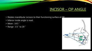
Incisor - OP angle
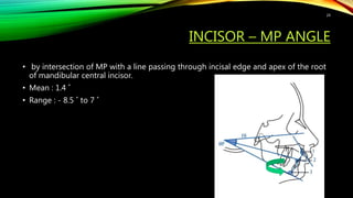
Incisor – MP angle
Incisor to A-pog
15](https://image.slidesharecdn.com/seminar4-hardtissuecephalometrics-210604040127/85/Hard-tissue-cephalometrics-15-320.jpg)
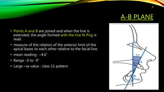
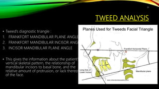
![FACIAL ANGLE
• to measure the degree of retrusion and
protrusion of mandible
• Inferior inside angle ; facial line [ nasion-
pogonion] intersects FH
• Mean reading : 87.8˚
• Range : 82 ˚ - 95 ˚
• > 87.8˚ = prominent chin
• < 87.8˚ = retrusive chin
16](https://image.slidesharecdn.com/seminar4-hardtissuecephalometrics-210604040127/85/Hard-tissue-cephalometrics-16-320.jpg)