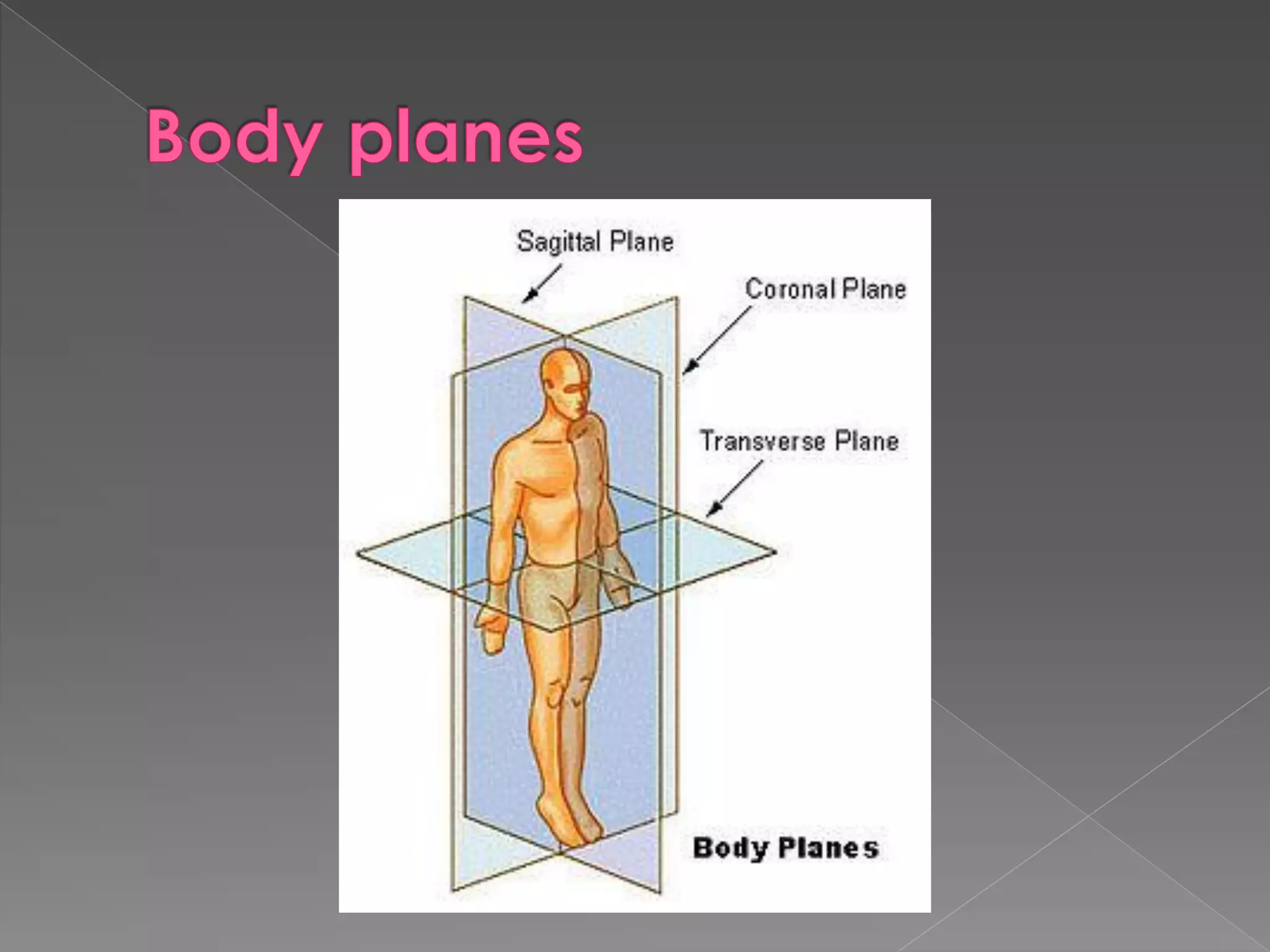
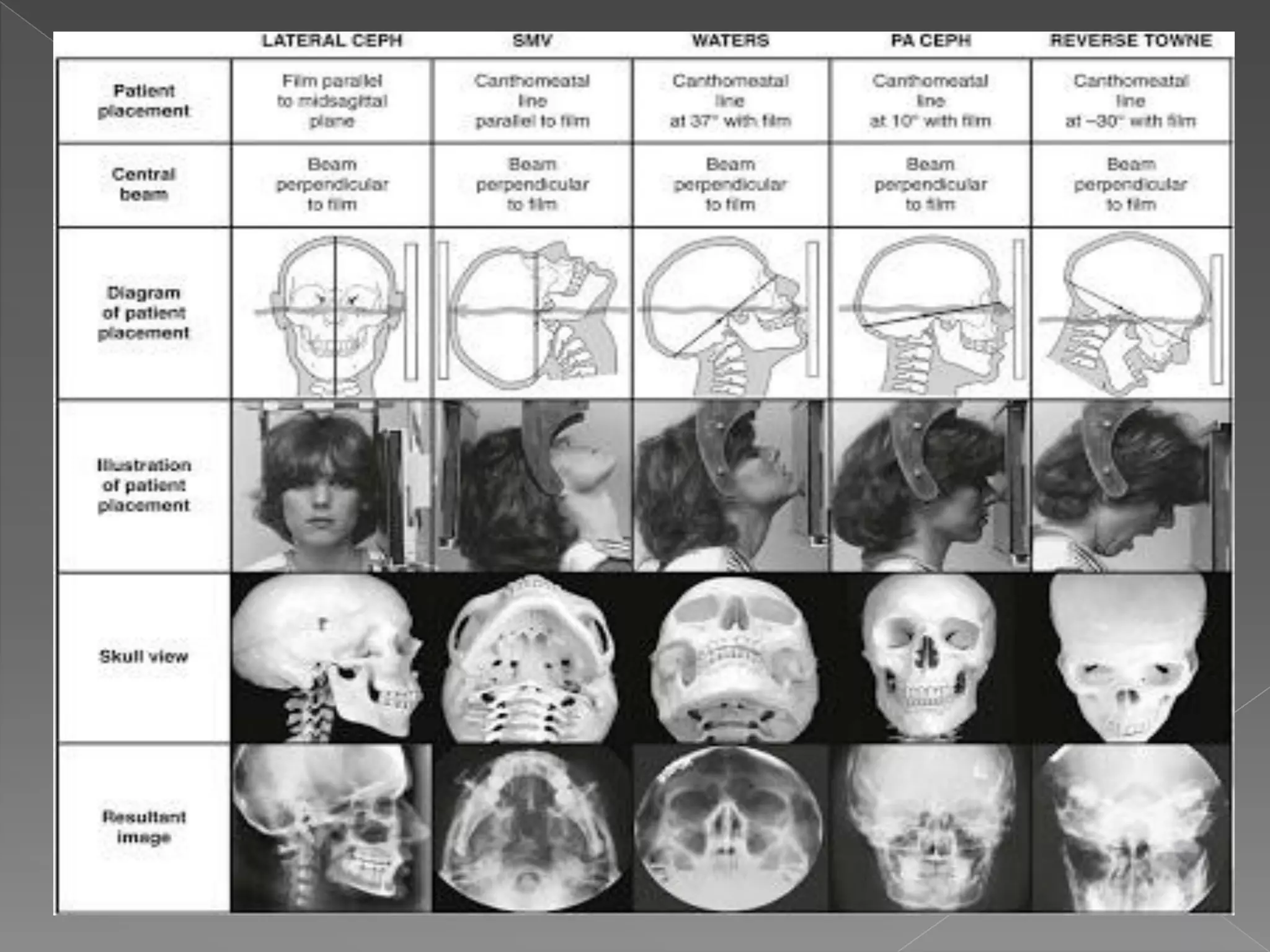
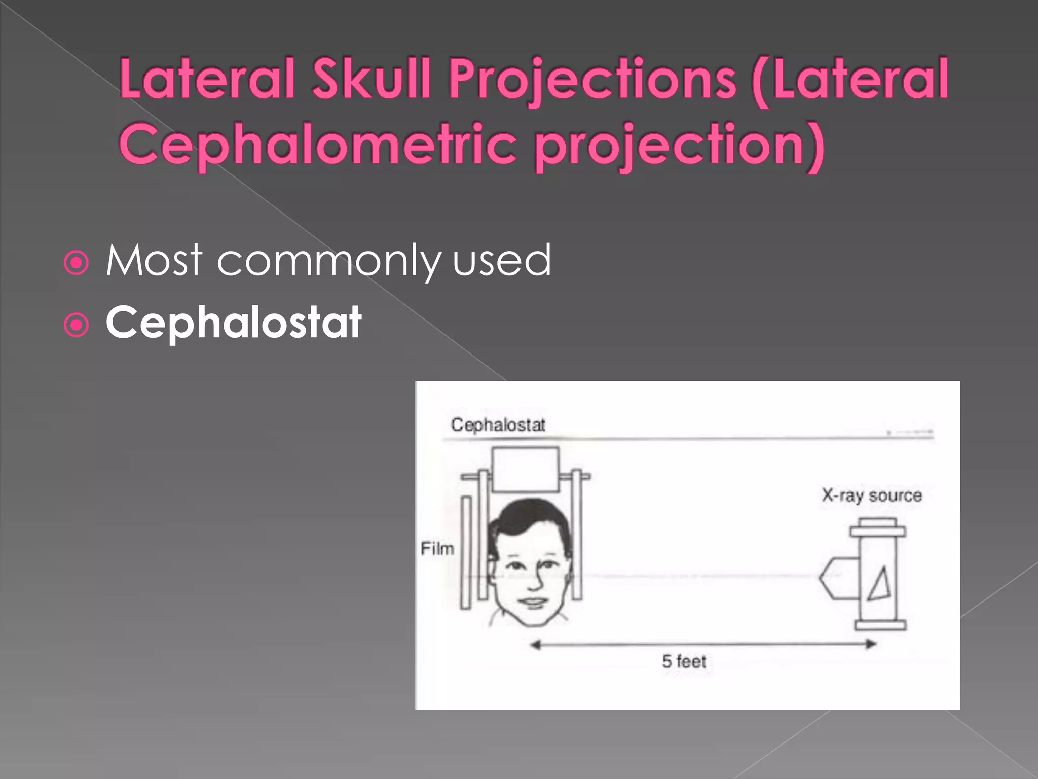
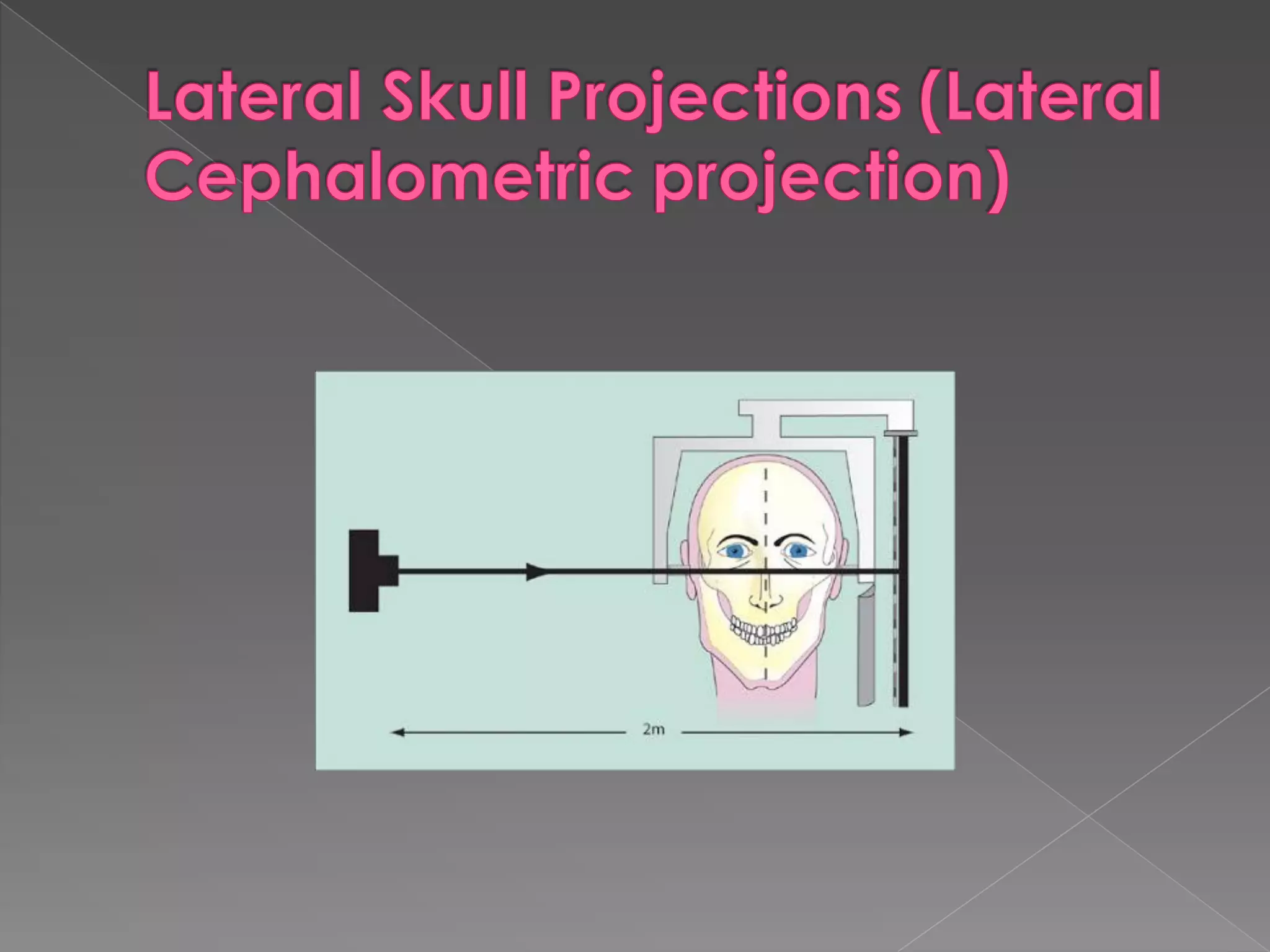
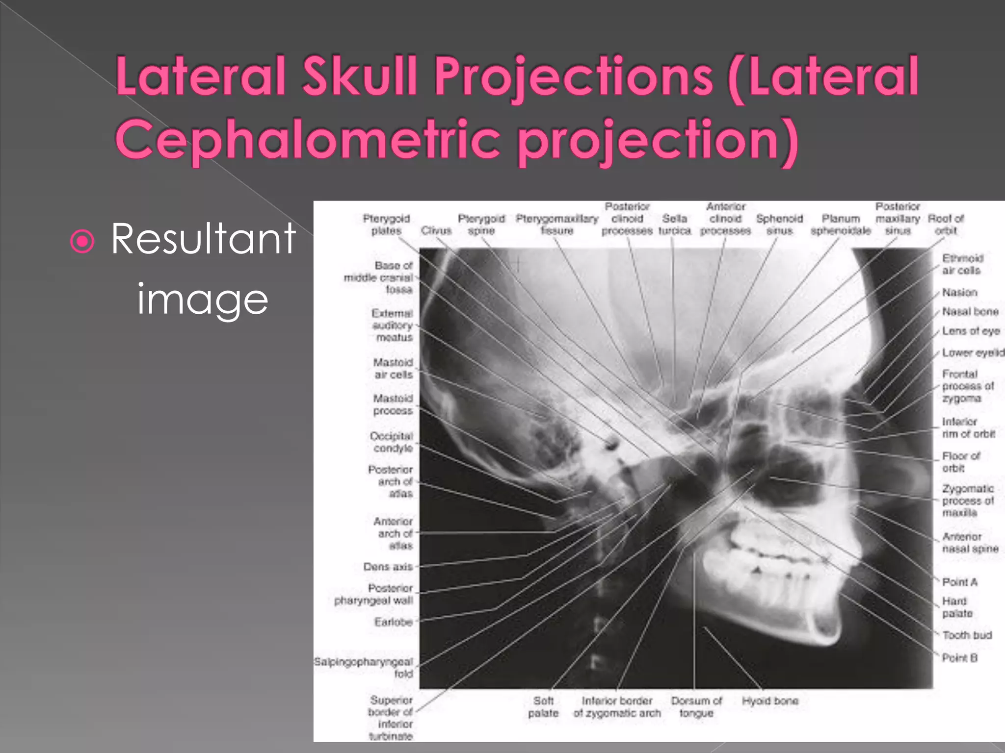
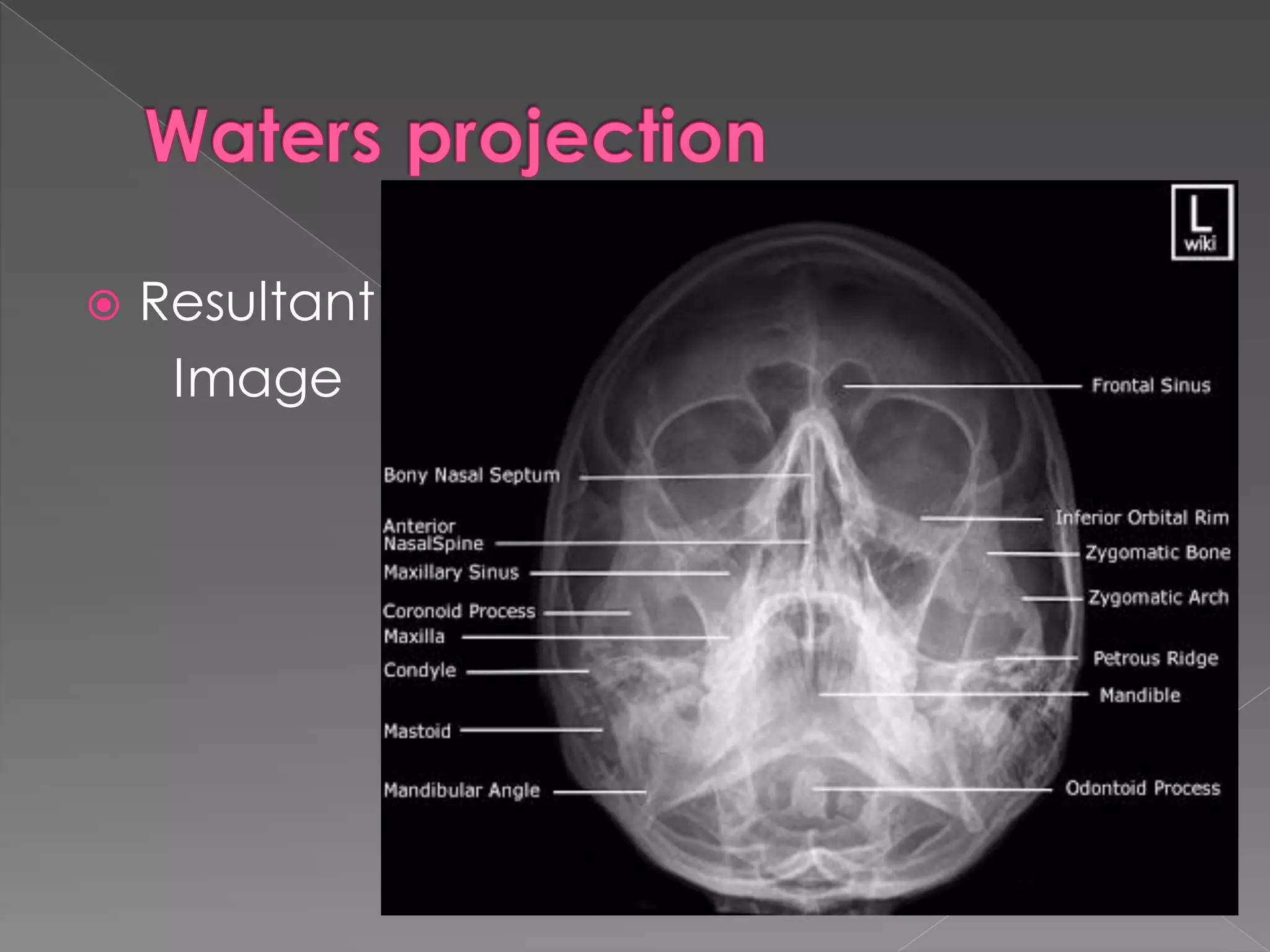
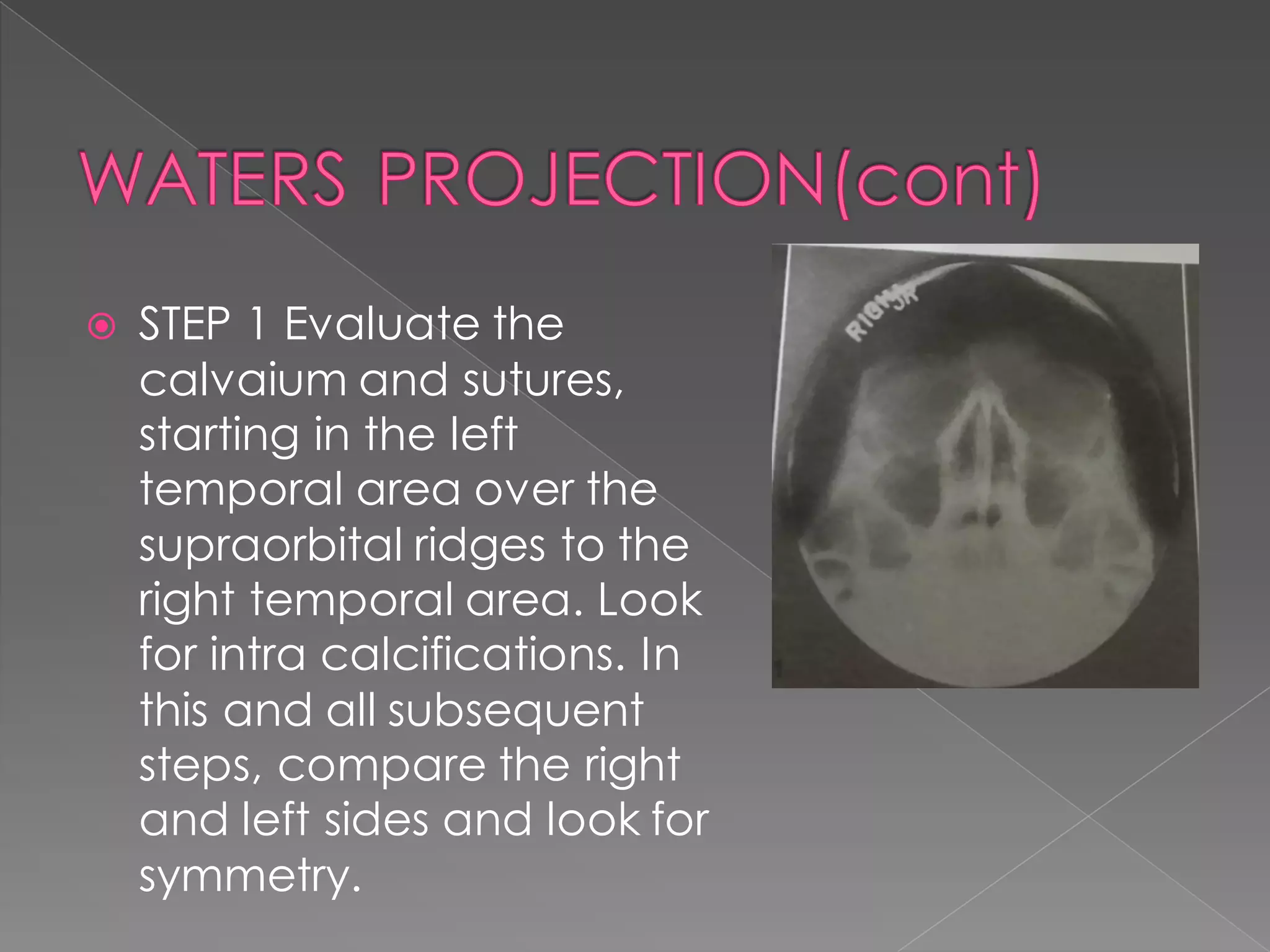
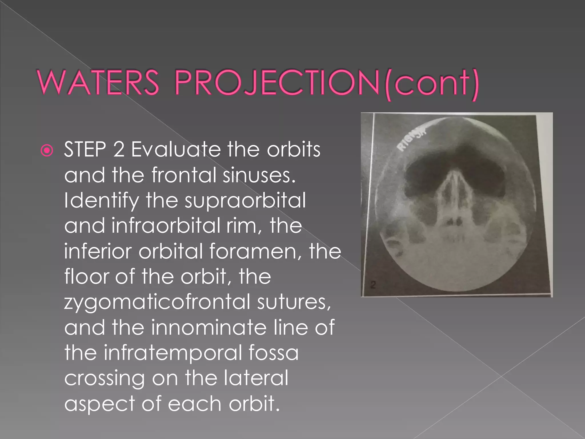
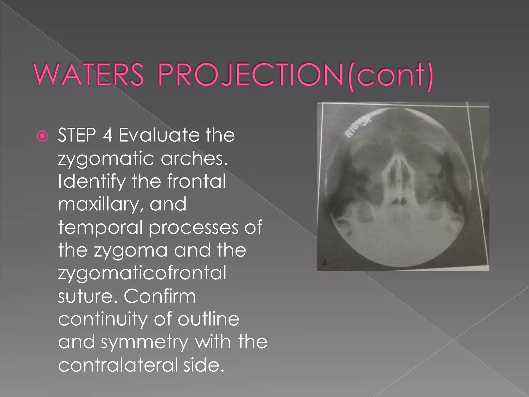
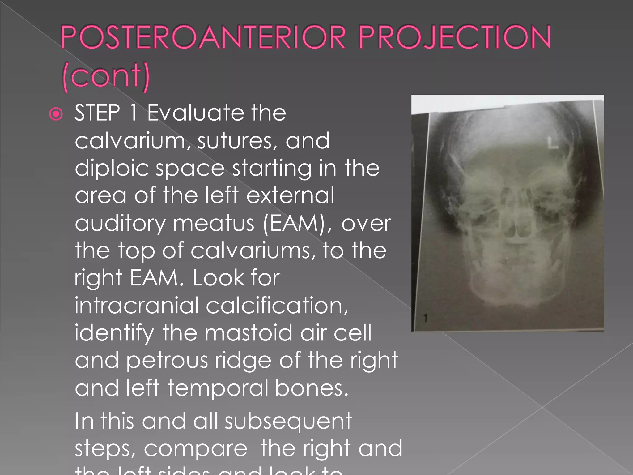
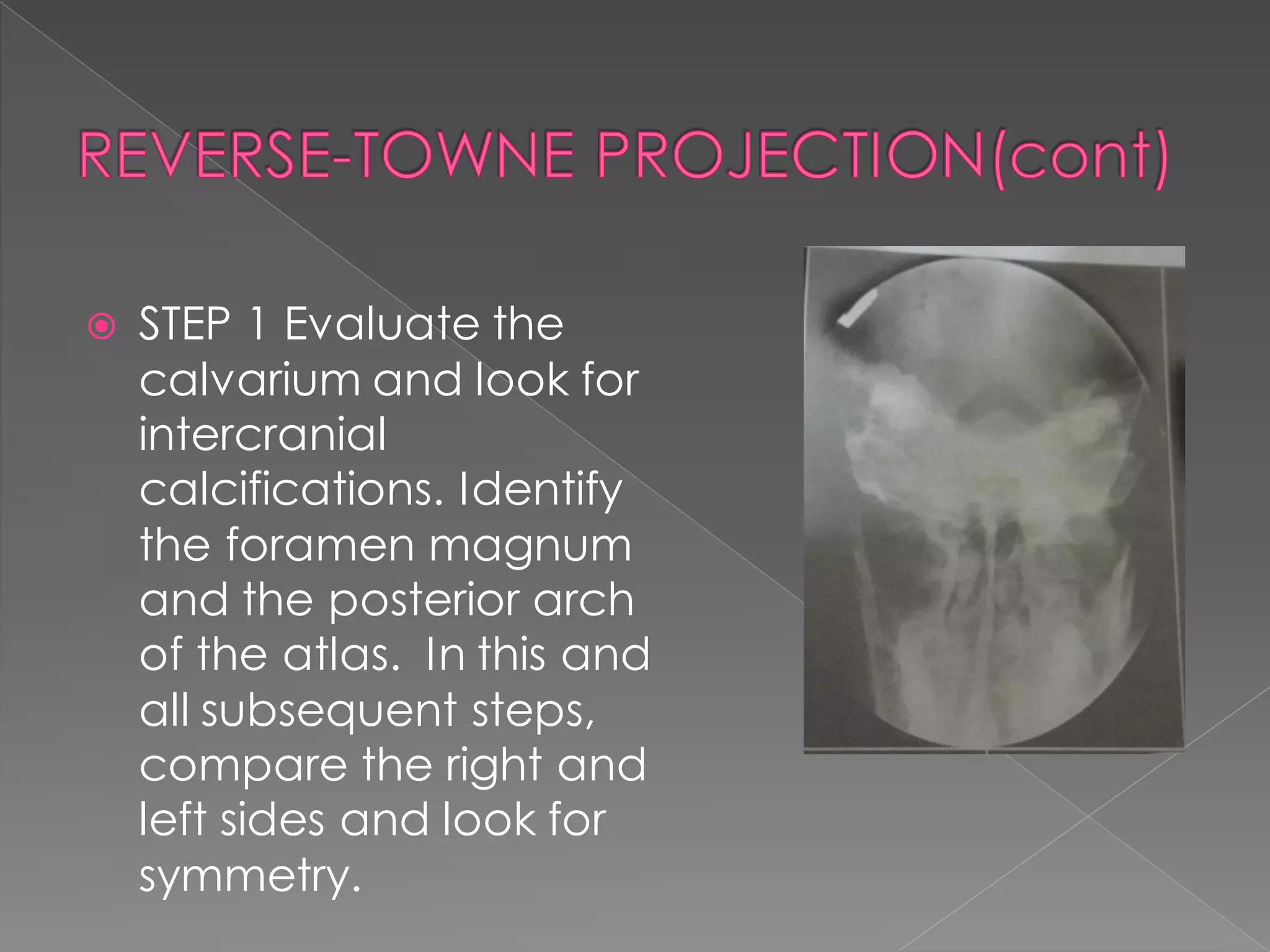
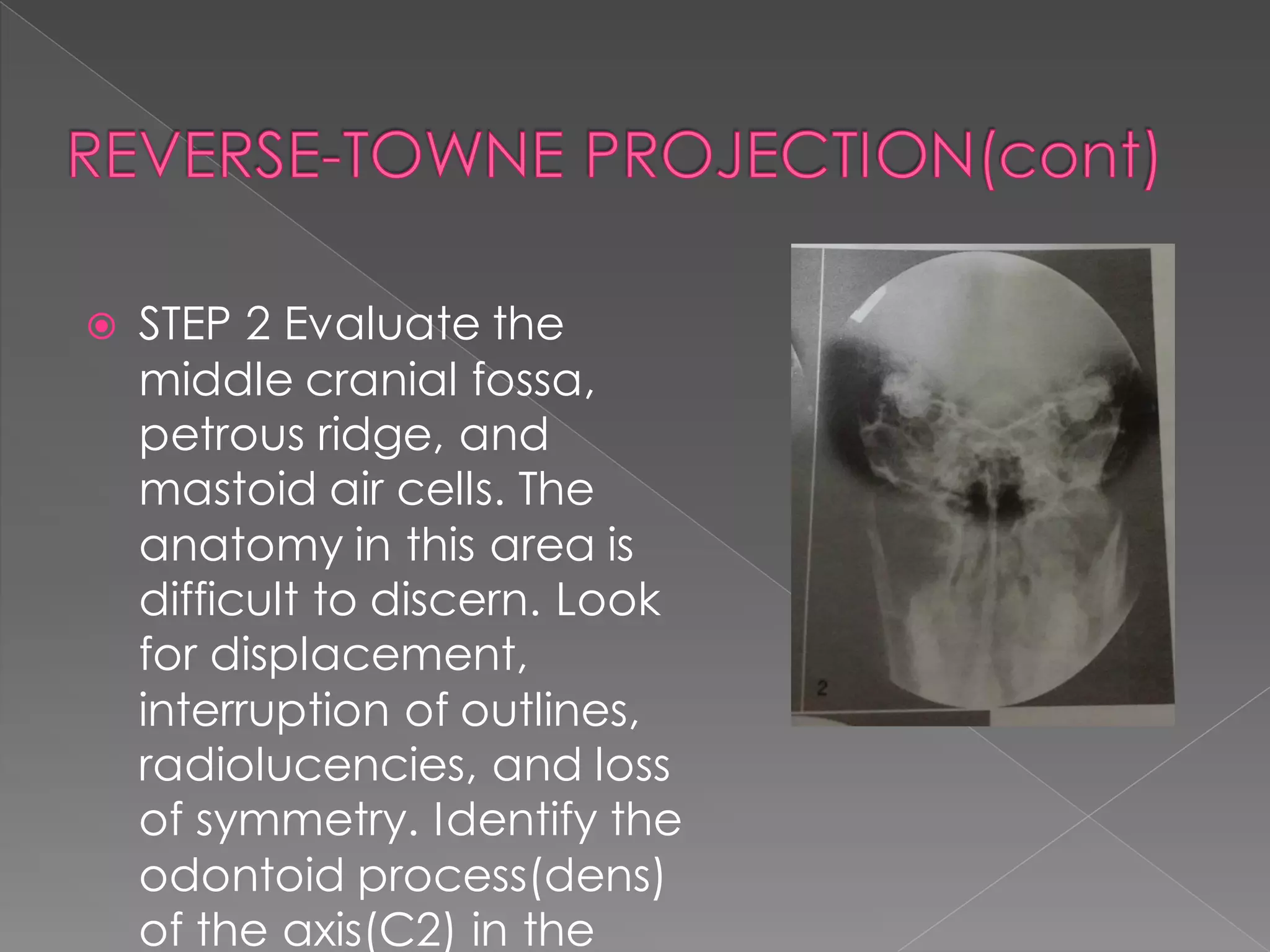
The document describes various radiographic projections used in cephalometry including:
1. Lateral cephalometric, posteroanterior cephalometric, and submentovertex projections which show anatomical structures of the skull from different angles.
2. Panoramic radiography which produces a single image of the upper and lower teeth and jaws.
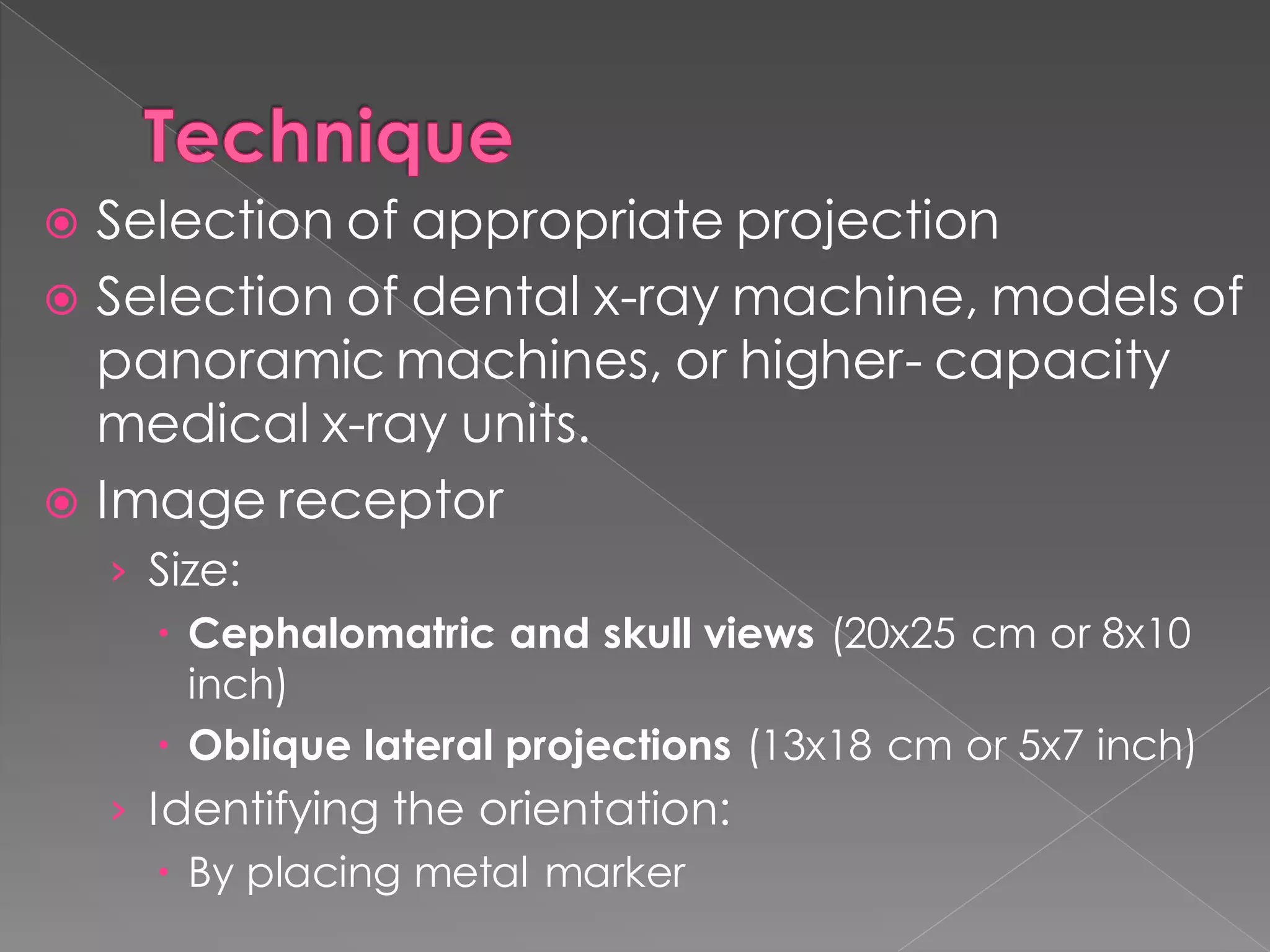
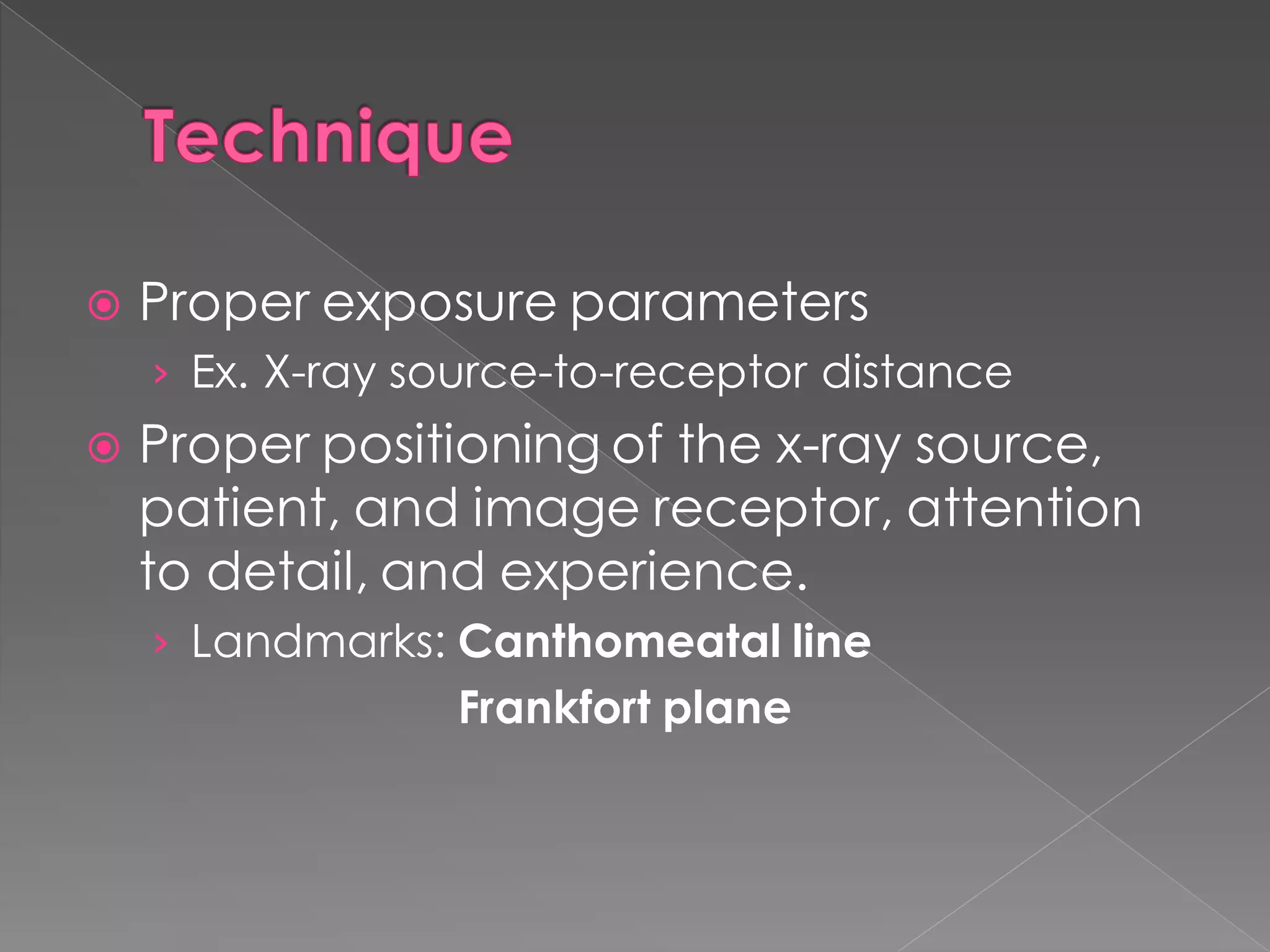
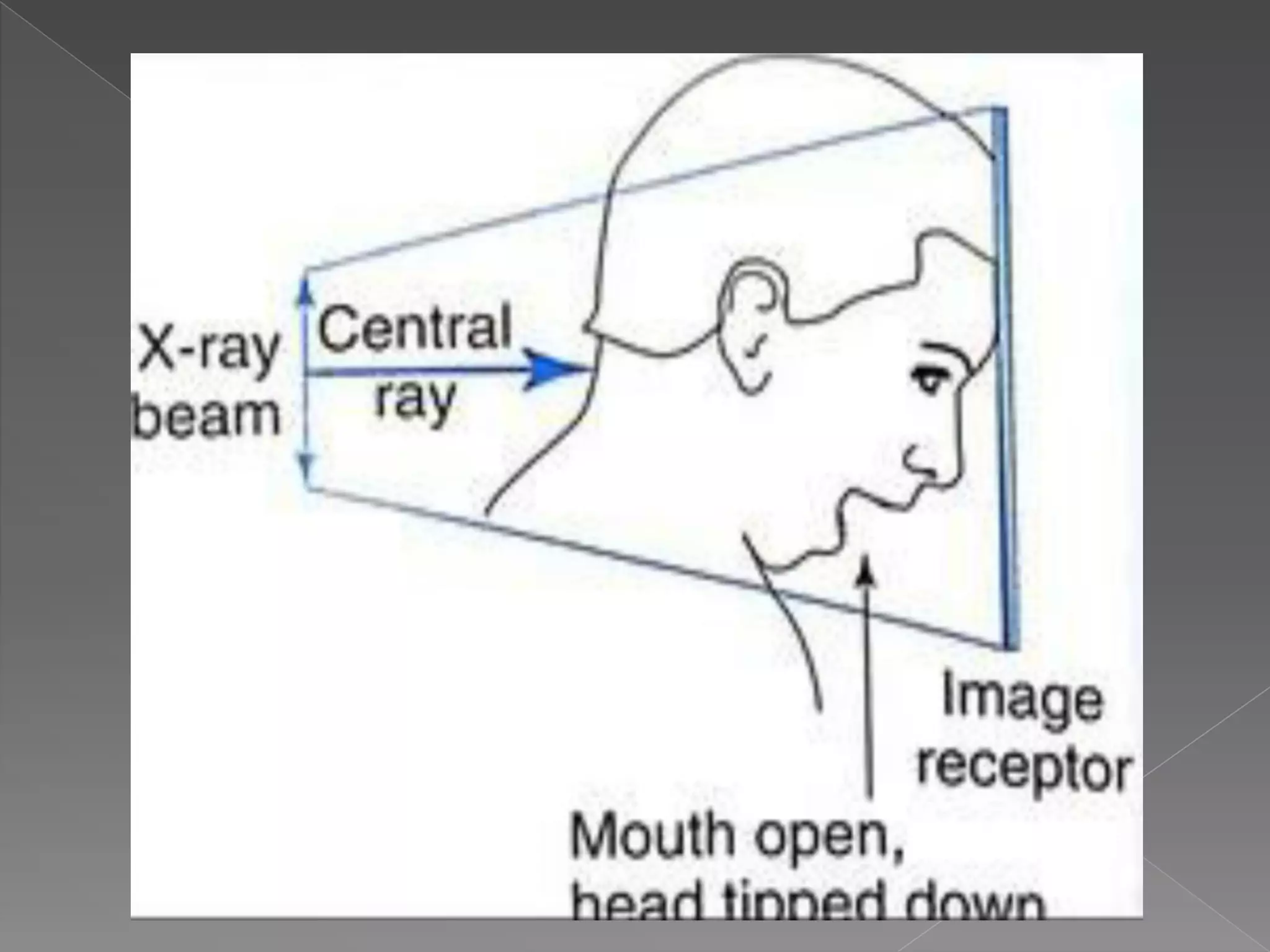
3. Proper technique involves correctly positioning the x-ray source, patient, and image receptor to obtain clear images while avoiding distortions and allowing identification of anatomical landmarks.