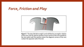
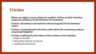
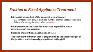
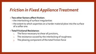
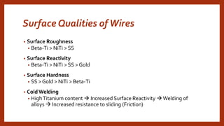
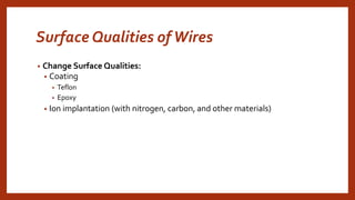
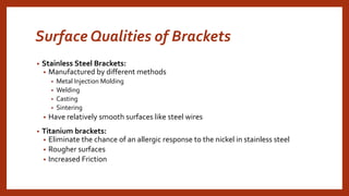
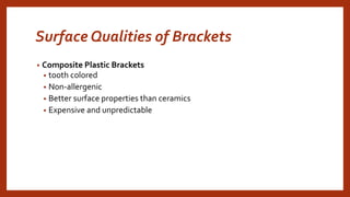
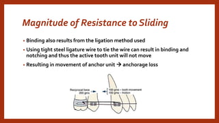
MECHANICAL ASPECTS
OF ANCHORAGE
CONTROL
Force, Friction and Play
How to Prevent Anchorage Loss?
• Reduce the amount of reactionary force on the anchorage unit
Friction
• When one object moves relative to another, friction at their interface
produces resistance to the direction of movement.
• Friction ultimately is derived from electromagnetic forces between
atoms
• Friction is proportional to the force with which the contacting surfaces
are pressed together
• Friction is affected by the nature of the surface at the interface
• rough or smooth
• chemically reactive or passive
• modified by lubricants
Friction in Fixed ApplianceTreatment
• Friction is independent of the apparent area of contact
• Real contact occurs only at a limited number of small spots at the peaks
of the surface irregularities, called asperities
• Local pressure at the asperities may cause appreciable plastic
deformation at the asperities
• Shearing of asperities on application of force
• The coefficient of friction then is proportional to the shear strength of
the junctions and is inversely proportional to the yield
Friction in Fixed ApplianceTreatment
• Two other factors affect friction:
• the interlocking of surface irregularities
• the extent to which asperities on a harder material plow into the surface
of a softer one
• Total Frictional Resistance:
1. The force necessary to shear all junctions,
2. The resistance caused by the interlocking of roughness
3. The plowing component of the total friction force
Surface Qualities ofWires
• Surface Roughness
• Beta-Ti > NiTi > SS
• Surface Reactivity
• Beta-Ti > NiTi > SS > Gold
• Surface Hardness
• SS > Gold > NiTi > Beta-Ti
• ColdWelding
• HighTitanium content  Increased Surface Reactivity Welding of
alloys  Increased resistance to sliding (Friction)
Surface Qualities ofWires
• Change Surface Qualities:
• Coating
• Teflon
• Epoxy
• Ion implantation (with nitrogen, carbon, and other materials)
Surface Qualities of Brackets
• Stainless Steel Brackets:
• Manufactured by different methods
• Metal Injection Molding
• Welding
• Casting
• Sintering
• Have relatively smooth surfaces like steel wires
• Titanium brackets:
• Eliminate the chance of an allergic response to the nickel in stainless steel
• Rougher surfaces
• Increased Friction
Surface Qualities of Brackets
• Ceramic brackets
• Esthetics
• Usually made from monocrystalline and
polycrystalline ceramics
• Surface is very rough and hard
• Penetrate the surface wire
• Ceramic brackets with metal slots
Surface Qualities of Brackets
• Composite Plastic Brackets
• tooth colored
• Non-allergenic
• Better surface properties than ceramics
• Expensive and unpredictable
Elastic and Inelastic Binding in
Resistance to Sliding
• RESISTANCETO SLIDING
• Resistance to sliding = Friction + Binding + Inelastic Binding
• If a tooth is pulled along an archwire
• The tooth will tip
• The corners of the bracket will come in contact with the wire
• The force with which bracket edges contact (bind) with wire will
increase resistance to sliding
• The greater the angle at which the wire contacts the corners of the
bracket, the greater the force between the wire and bracket
Binding – Narrow vsWide Brackets
Slot Size
• 22 x 28
• Designed to be used with gold wires
• 18 x 25
• Designed to be used with stainless steel wires
Inelastic Binding - Notching
• A nick or notch is formed at the edge of wire
• Mechanical hindrance in sliding
• Common when combination of different materials is used
Magnitude of Resistance to Sliding
• Binding also results from the ligation method used
• Using tight steel ligature wire to tie the wire can result in binding and
notching and thus the active tooth unit will not move
• Resulting in movement of anchor unit  anchorage loss
Frictionless Mechanics
• Use of loops and springs
• Retraction springs
• Closing loops
Frictionless Mechanics
• Benefits of Loops
• Frictionless mechanics
• Tooth movement can be carried out with lighter forces
• Tooth movements are more predictable
• Better control of anchor units, occlusal plane, arch form and midlines
• Disadvantages of Closing loops
• More complex to design
• Less patient friendly (hygiene and esthetics)
• Distortions may cause injury or changed forces system
Methods to Control Anchorage
• Reinforcement
• The extent to which anchorage should be reinforced (by adding teeth to
the anchorage unit)
• For significant differential tooth movement:
• The ratio of PDL area in the anchorage unit to PDL area in the tooth
movement unit should be at least 2 to 1 without sliding
• With sliding forces - 4 to 1
Subdivision of Desired Movements
• Dividing the arch into equal segments cannot cause differential
movements
• Pit the resistance of a group of teeth against the movement of a single
tooth
• E.g. Retract canine against the mesial movement of whole posterior
segment
How to achieve differential retraction of
incisors?
• Closure of a premolar extraction site often is desired in a ratio of 60%
retraction of incisors, 40% forward movement of posterior segment
• Methods:
1. one-step space closure with no sliding (closing loop)
2. two-step space closure with sliding mechanics, retracting the canine
individually, and then retracting the four incisors in a second step (the
classicTweed approach)
3. two-step sliding with distal tipping of the canine and incisors initially,
followed by uprighting of these teeth (the classic Begg approach)
DETERMINATEVERSUS
INDETERMINATE
FORCE SYSTEMS
Force System
• Consists of:
• Body or multiple bodies/structures (Tooth or group of teeth)
• Forces (in any of the three dimensions – can be additive or subtractive)
• Moments (can be clockwise / anticlockwire – can be additive or
subtractive)
Determinate Force System
• A force system in which all moment and forces
can be calculated
• E.g. One couple system
• Cantilever Spring
Indeterminate Force System
• A force system in which all moment and forces can not be calculated
• There can be too many forces and moments
• Or forces and moments may change their magnitude and direction
rapidly
• E.g.Two couple system
• Ricket’s Utility Arch
One-Couple Systems
• One-couple systems are found when two conditions are met:
• (1) One end of wire is placed into a bracket or tube (making two
contacts) and typically attaches to anchor segment
• (2) the other end of the wire is tied to a tooth or group of teeth with at a
single point of contact
Two-Couple Systems
• Two-couple systems are found when two conditions are met:
1. One end of wire is placed into a bracket or tube (making two contacts)
and typically attaches to anchor segment
2. The other end of the wire is also placed in a bracket or tube to a tooth
or group of teeth with two points of contact
Segmental Arch Mechanics
• Each segments acts as a giant tooth having its own center of resistance
• Segments are usually connected with loops or frictionless mechanics
• If single point contact is made in one of the segments – One couple
system – Determinate force system
• If two point contacts are made in each segment –Two couple system –
Indeterminate force system
Continuous Arch Mechanics
• A single wire is passing through all brackets
• Couples are being generated in each bracket
• The force system is changing with even minor tooth movements
• Example of indeterminate force system
QUESTIONS?

mechanical aspects of anchorage control

  • 1.
  • 2.
  • 3.
    How to PreventAnchorage Loss? • Reduce the amount of reactionary force on the anchorage unit
  • 4.
    Friction • When oneobject moves relative to another, friction at their interface produces resistance to the direction of movement. • Friction ultimately is derived from electromagnetic forces between atoms • Friction is proportional to the force with which the contacting surfaces are pressed together • Friction is affected by the nature of the surface at the interface • rough or smooth • chemically reactive or passive • modified by lubricants
  • 7.
    Friction in FixedApplianceTreatment • Friction is independent of the apparent area of contact • Real contact occurs only at a limited number of small spots at the peaks of the surface irregularities, called asperities • Local pressure at the asperities may cause appreciable plastic deformation at the asperities • Shearing of asperities on application of force • The coefficient of friction then is proportional to the shear strength of the junctions and is inversely proportional to the yield
  • 8.
    Friction in FixedApplianceTreatment • Two other factors affect friction: • the interlocking of surface irregularities • the extent to which asperities on a harder material plow into the surface of a softer one • Total Frictional Resistance: 1. The force necessary to shear all junctions, 2. The resistance caused by the interlocking of roughness 3. The plowing component of the total friction force
  • 9.
    Surface Qualities ofWires •Surface Roughness • Beta-Ti > NiTi > SS • Surface Reactivity • Beta-Ti > NiTi > SS > Gold • Surface Hardness • SS > Gold > NiTi > Beta-Ti • ColdWelding • HighTitanium content  Increased Surface Reactivity Welding of alloys  Increased resistance to sliding (Friction)
  • 10.
    Surface Qualities ofWires •Change Surface Qualities: • Coating • Teflon • Epoxy • Ion implantation (with nitrogen, carbon, and other materials)
  • 11.
    Surface Qualities ofBrackets • Stainless Steel Brackets: • Manufactured by different methods • Metal Injection Molding • Welding • Casting • Sintering • Have relatively smooth surfaces like steel wires • Titanium brackets: • Eliminate the chance of an allergic response to the nickel in stainless steel • Rougher surfaces • Increased Friction
  • 12.
    Surface Qualities ofBrackets • Ceramic brackets • Esthetics • Usually made from monocrystalline and polycrystalline ceramics • Surface is very rough and hard • Penetrate the surface wire • Ceramic brackets with metal slots
  • 13.
    Surface Qualities ofBrackets • Composite Plastic Brackets • tooth colored • Non-allergenic • Better surface properties than ceramics • Expensive and unpredictable
  • 14.
    Elastic and InelasticBinding in Resistance to Sliding • RESISTANCETO SLIDING • Resistance to sliding = Friction + Binding + Inelastic Binding • If a tooth is pulled along an archwire • The tooth will tip • The corners of the bracket will come in contact with the wire • The force with which bracket edges contact (bind) with wire will increase resistance to sliding • The greater the angle at which the wire contacts the corners of the bracket, the greater the force between the wire and bracket
  • 15.
    Binding – NarrowvsWide Brackets
  • 16.
    Slot Size • 22x 28 • Designed to be used with gold wires • 18 x 25 • Designed to be used with stainless steel wires
  • 17.
    Inelastic Binding -Notching • A nick or notch is formed at the edge of wire • Mechanical hindrance in sliding • Common when combination of different materials is used
  • 18.
    Magnitude of Resistanceto Sliding • Binding also results from the ligation method used • Using tight steel ligature wire to tie the wire can result in binding and notching and thus the active tooth unit will not move • Resulting in movement of anchor unit  anchorage loss
  • 19.
    Frictionless Mechanics • Useof loops and springs • Retraction springs • Closing loops
  • 20.
    Frictionless Mechanics • Benefitsof Loops • Frictionless mechanics • Tooth movement can be carried out with lighter forces • Tooth movements are more predictable • Better control of anchor units, occlusal plane, arch form and midlines • Disadvantages of Closing loops • More complex to design • Less patient friendly (hygiene and esthetics) • Distortions may cause injury or changed forces system
  • 21.
    Methods to ControlAnchorage • Reinforcement • The extent to which anchorage should be reinforced (by adding teeth to the anchorage unit) • For significant differential tooth movement: • The ratio of PDL area in the anchorage unit to PDL area in the tooth movement unit should be at least 2 to 1 without sliding • With sliding forces - 4 to 1
  • 22.
    Subdivision of DesiredMovements • Dividing the arch into equal segments cannot cause differential movements • Pit the resistance of a group of teeth against the movement of a single tooth • E.g. Retract canine against the mesial movement of whole posterior segment
  • 23.
    How to achievedifferential retraction of incisors? • Closure of a premolar extraction site often is desired in a ratio of 60% retraction of incisors, 40% forward movement of posterior segment • Methods: 1. one-step space closure with no sliding (closing loop) 2. two-step space closure with sliding mechanics, retracting the canine individually, and then retracting the four incisors in a second step (the classicTweed approach) 3. two-step sliding with distal tipping of the canine and incisors initially, followed by uprighting of these teeth (the classic Begg approach)
  • 25.
  • 26.
    Force System • Consistsof: • Body or multiple bodies/structures (Tooth or group of teeth) • Forces (in any of the three dimensions – can be additive or subtractive) • Moments (can be clockwise / anticlockwire – can be additive or subtractive)
  • 27.
    Determinate Force System •A force system in which all moment and forces can be calculated • E.g. One couple system • Cantilever Spring
  • 29.
    Indeterminate Force System •A force system in which all moment and forces can not be calculated • There can be too many forces and moments • Or forces and moments may change their magnitude and direction rapidly • E.g.Two couple system • Ricket’s Utility Arch
  • 31.
    One-Couple Systems • One-couplesystems are found when two conditions are met: • (1) One end of wire is placed into a bracket or tube (making two contacts) and typically attaches to anchor segment • (2) the other end of the wire is tied to a tooth or group of teeth with at a single point of contact
  • 33.
    Two-Couple Systems • Two-couplesystems are found when two conditions are met: 1. One end of wire is placed into a bracket or tube (making two contacts) and typically attaches to anchor segment 2. The other end of the wire is also placed in a bracket or tube to a tooth or group of teeth with two points of contact
  • 36.
    Segmental Arch Mechanics •Each segments acts as a giant tooth having its own center of resistance • Segments are usually connected with loops or frictionless mechanics • If single point contact is made in one of the segments – One couple system – Determinate force system • If two point contacts are made in each segment –Two couple system – Indeterminate force system
  • 37.
    Continuous Arch Mechanics •A single wire is passing through all brackets • Couples are being generated in each bracket • The force system is changing with even minor tooth movements • Example of indeterminate force system
  • 38.