- Cephalometrics involves analyzing and measuring radiographic images of the head called cephalograms. Key landmarks are identified and linear and angular measurements are made between landmarks to assess craniofacial structures.
- There are several commonly used analyses in orthodontics including Downs analysis, Steiner analysis, Tweed analysis, and the Wits appraisal. These analyses establish norms for skeletal and dental relationships and angles that can be used to diagnose malocclusions.
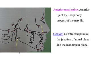
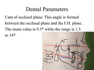
- Landmarks, reference planes like the Frankfort horizontal and mandibular planes, and angular and linear measurements between them allow for evaluation of the positions of jaws, teeth, and soft tissues to develop treatment plans. Serial cephalograms also enable