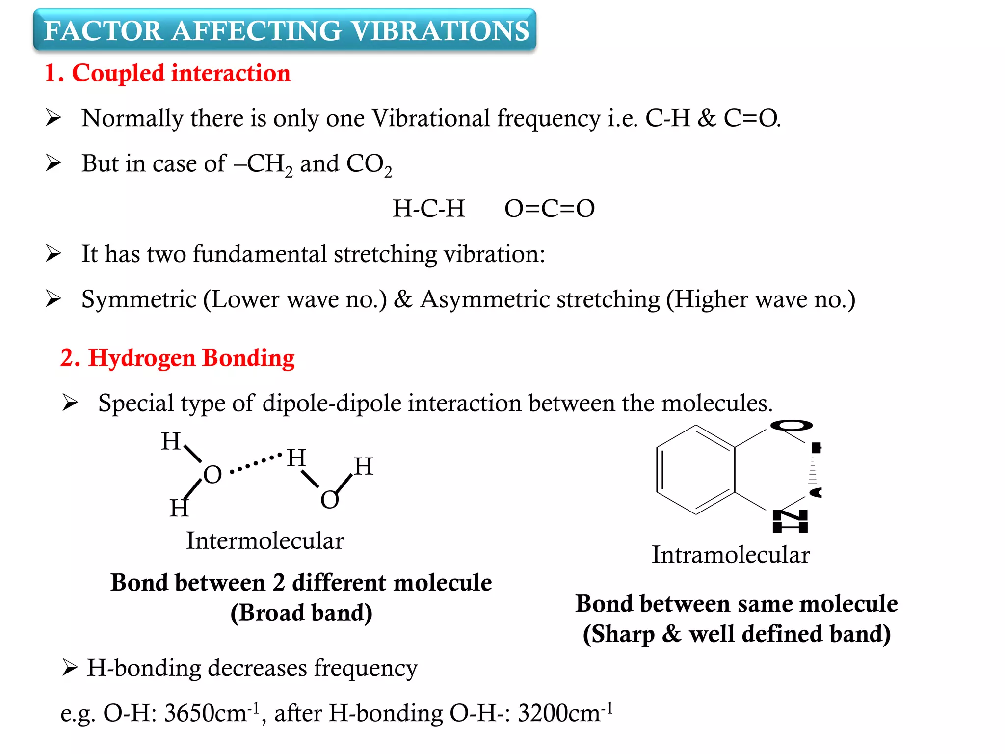
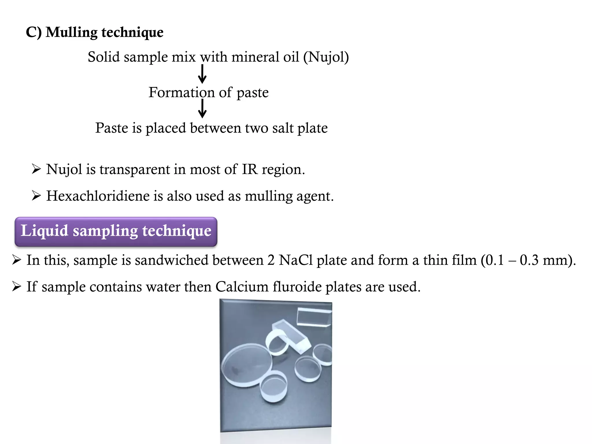
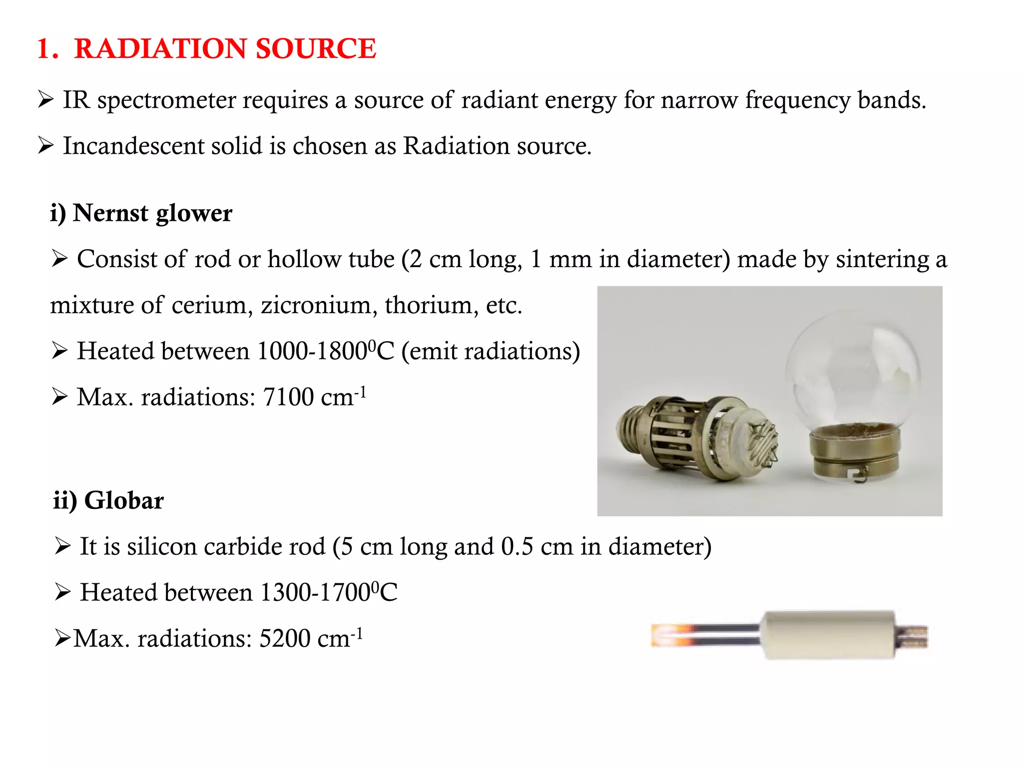
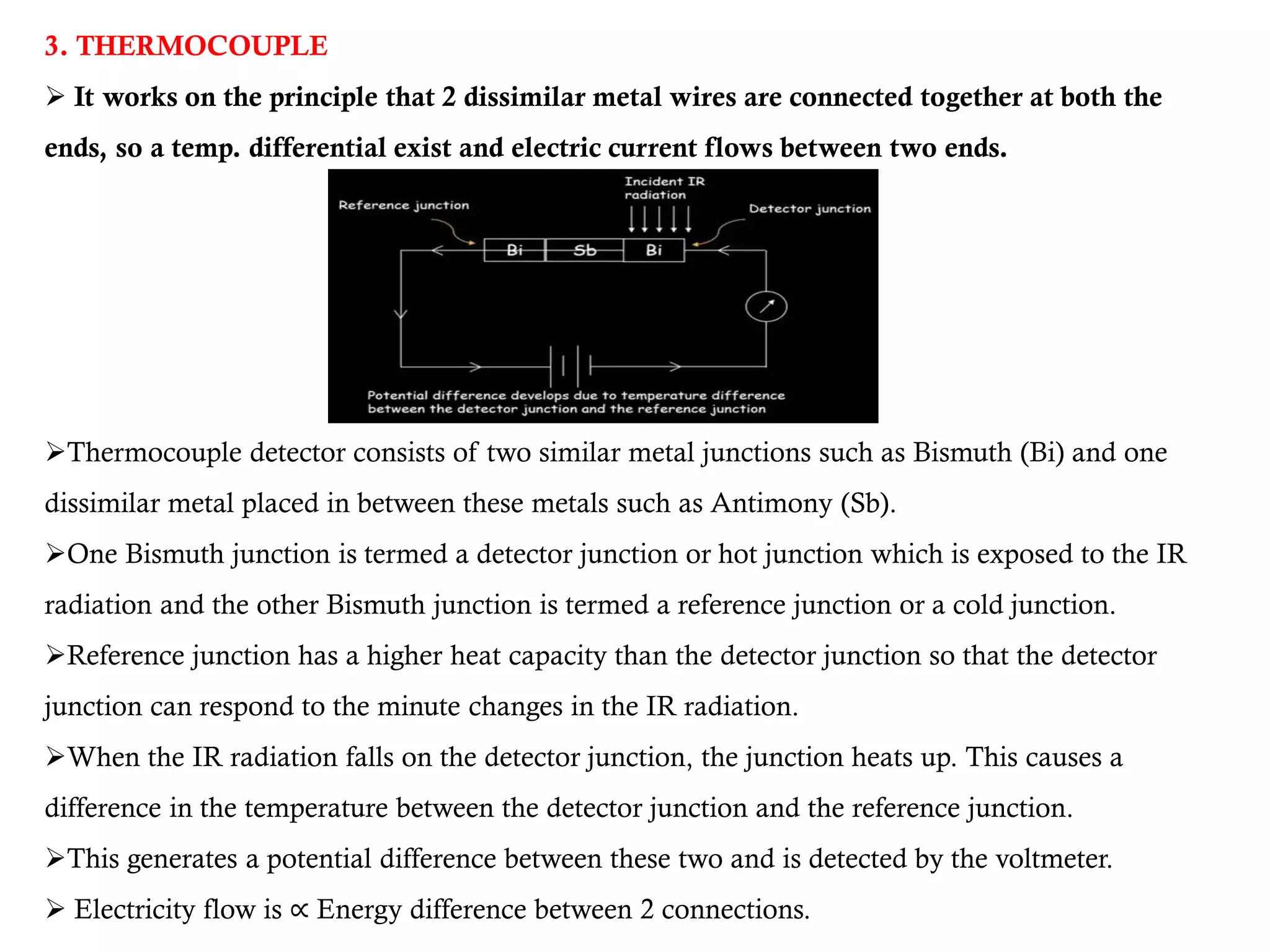
 Introduction,
 Fundamental modes of vibrations in poly atomic
molecules,
 Sample handling,
 Factors affecting vibrations
 Instrumentation - Sources of radiation,
wavelength selectors, Detectors
Applications
CONTENT
 It is a type of absorption spectroscopy.
 Analytical technique used for qualitative and quantitative analysis of sample by
using IR region of EMR.
 Basically used in identification of compounds by determining its structure and
functional group.
 Functional group have unique and separate fingerprint structure.
IR region is divided into 3 regions:
1. Near: 14000 – 4000 cm-1
2. Mid: 4000 – 400 cm-1
3. Far: 400 – 10 cm-1
 Each functional group has specific wave number (frequency of absorption)
INTRODUCTION
 When frequency of radiations is equal to vibration frequency of molecule,
absorption of IR radiation takes place and peak is recorded.
IR Radiations Detector
2783 – 2843 cm-1
PRINCIPLE
TYPICAL IR ABSORPTION FREQUENCIES
 Only applicable for compounds having matching frequencies (Range of wave number).
 Change in dipole moment is also essential.
 A molecule will absorb IR radiation if the change in Vibrational states is associated
with a change in the dipole moment of the molecule.
 Vibrations which do not change the dipole moment are IR inactive (Homonuclear
diatomics)
 Homonuclear diatomic molecules: O2, N2, H2, Cl2
 Heteronuclear diatomic molecules: HF, HCl
SELECTION RULE
FUNDAMENTAL MODES OF VIBRATIONS
 Movement of molecule when it absorbs IR radiations.
 They are of 2 types of vibrations.
1. Stretching Vibrations
Distance between 2 atoms increases or decreases but in the same axis.
It is further subdivided into 2 types:
a) Symmetric stretching
Movement of atoms in the same directions.
b) Asymmetric stretching
Movement of atoms in the opposite directions.
2. Bending Vibrations
 In this, position of atoms changes with respect to original bond axis.
 Stretching absorption of bond appears at higher frequencies than bending
absorption.
It is further subdivided into 4 types:
a) Scissoring
 2 atoms approaches each other.
b) Rocking
 Movement of atoms in the same directions.
c) Wagging
 2 atoms moves up & down the plane with respect to central atom.
d) Twisting
 1 atoms moves up the plane & other moves down the plane with respect to
central atom.
FACTOR AFFECTING VIBRATIONS
1. Coupled interaction
 Normally there is only one Vibrational frequency i.e. C-H & C=O.
 But in case of –CH2 and CO2
H-C-H O=C=O
 It has two fundamental stretching vibration:
 Symmetric (Lower wave no.) & Asymmetric stretching (Higher wave no.)
2. Hydrogen Bonding
 Special type of dipole-dipole interaction between the molecules.
H
H
O
H
O
H
Intermolecular
Intramolecular
Bond between 2 different molecule
(Broad band) Bond between same molecule
(Sharp & well defined band)
 H-bonding decreases frequency
e.g. O-H: 3650cm-1, after H-bonding O-H-: 3200cm-1
N
H
O
H
O
3. Resonance effect
It will increase the bond length which decreases the frequency.
(Bond sharing: Increase bond length)
e.g.
1715 cm-1
1690 cm-1
4. Electronic effect (Inductive effect)
Frequency will change by changing the substituents of neighbors group.
Inductive Effect
+ I effect (ERG) - I effect (EWG)
Frequency Bond length Frequency
CH3 C
O
CH CH2
CH3
H
C O
H
H
C O
1750 cm-1
1745 cm-1
C O
C
H
3
C
H
3
C
l C
H
2
C
C
l C
H
2
O
1725 cm-1
1740 cm-1
SAMPLE HANDLING TECHNIQUES
Solid Sampling
Technique
Liquid Sampling
Technique
Gas Sampling
Technique
Solution Sampling
Technique
Solid sampling technique
Preparation of solid sample:
A) Direct sampling: Solid sample is put in sample holder.
B) Pellatization technique:
Solid sample + KBr
Pass under high pressure in press
Formation of small thick (1-2 mm) pellets. (1 cm in diameter)
 Pellets are transparent to IR radiations.
 KBr, NaCl are only used for IR suitable compounds.
C) Mulling technique
Solid sample mix with mineral oil (Nujol)
Formation of paste
Paste is placed between two salt plate
 Nujol is transparent in most of IR region.
 Hexachloridiene is also used as mulling agent.
Liquid sampling technique
 In this, sample is sandwiched between 2 NaCl plate and form a thin film (0.1 – 0.3 mm).
 If sample contains water then Calcium fluroide plates are used.
Gas sampling technique
 In this, aqueous sample is placed into gas cell (10 cm long) made from NaCl wall.
Solution sampling technique
 In this, aqueous sample is dissolved in suitable solvents then analyzed in the form
of solution.
 Commonly used solvents: Chloroform, Carbon tetrachloride, Carbon disulfide,
etc.
INSTRUMENTATION
Typically it consist of following parts:
1. Radiation source
2. Monochromator
3. Sample cell
4. Detector
5. Read out system
1. RADIATION SOURCE
 IR spectrometer requires a source of radiant energy for narrow frequency bands.
 Incandescent solid is chosen as Radiation source.
i) Nernst glower
 Consist of rod or hollow tube (2 cm long, 1 mm in diameter) made by sintering a
mixture of cerium, zicronium, thorium, etc.
 Heated between 1000-18000C (emit radiations)
 Max. radiations: 7100 cm-1
ii) Globar
 It is silicon carbide rod (5 cm long and 0.5 cm in diameter)
 Heated between 1300-17000C
Max. radiations: 5200 cm-1
iii) Nichrome wire
 A coil of thin wire heated by passing current.
It is a tightly wound coil of nichrome (Ni-Cr) wire, electrically heated
to 1100 K. It produces a lower intensity of radiation than the Nernst or
Globar sources, but has a longer working life.
iv) Rhodium wire
 Wire is sealed in a cylinder.
It is used when the required wavelength range and intensity
are not too great.
v) Tungsten filament lamp
 Mainly used for near IR region.
The lamp consists of a tungsten filament in a evacuated glass or
quartz envelope that contains a small amount of iodine vapor to
increase the lifetime of the filament.
2. MONOCHROMATOR
 Radiation source emits radiations of various frequencies.
 Used for selection of certain frequencies and for rejection of other frequencies.
Types:
1. Prism: Dispersive element made from NaCl
2. Grating: Causes linear and higher dispersion.
3. SAMPLE CELLS
 Different sampling techniques are used for insertion of sample into sample cell.
4. DETECTOR
Thermal detectors are used for IR (depends on heat energy)
1. GOLAY CELL
Principle: When IR radiation is absorbed by the gas present in the chamber, the gas
expands and deforms the flexible membrane which results in the deflection of light
from the membrane which is then detected by the photodiode array detector.
 It has smaller cylinder with one end of blackened metal plate and other flexible
diaphragm mirror.
 It is filled with Xenon gas.
 When IR radiations falls on blackened metal plate then gas heat up and expands that
increase the pressure & then deform the metalized diaphragm mirror.
2. BOLOMETER
 It works on the principle, increase in temp. results in increase in electrical
resistance of metal.
i.e. 10C increase – 0.4 % increase in Resistance
 It consist of a thin metal conductor whose temp. changes when IR radiations falls
on it which further changes the resistance.
 On the basis of resistance, IR intensity is calculated.
3. THERMOCOUPLE
 It works on the principle that 2 dissimilar metal wires are connected together at both the
ends, so a temp. differential exist and electric current flows between two ends.
Thermocouple detector consists of two similar metal junctions such as Bismuth (Bi) and one
dissimilar metal placed in between these metals such as Antimony (Sb).
One Bismuth junction is termed a detector junction or hot junction which is exposed to the IR
radiation and the other Bismuth junction is termed a reference junction or a cold junction.
Reference junction has a higher heat capacity than the detector junction so that the detector
junction can respond to the minute changes in the IR radiation.
When the IR radiation falls on the detector junction, the junction heats up. This causes a
difference in the temperature between the detector junction and the reference junction.
This generates a potential difference between these two and is detected by the voltmeter.
 Electricity flow is ∝ Energy difference between 2 connections.
4. THERMISTOR
 It is made up of fused mixture of metal oxides.
 It is same as that of Bolometer, but in this electrical resistance of mixture
decreases with increase in temperature.
T ∝ 1 / R, 10C increase – 5 % Resistance decrease
 One advantage of a thermistor over a Bolometer is that the response time is rapid
which gives improved resolution and faster screening rates. But the sensitivity of
the thermistor is poorer as compared to the bolometer.
5. PYROELECTRIC
 It contain a pyroelectric material which produce electricity on changing thermal
energy.
 In this dielectric material is placed between electrodes.
When IR radiations exposed to black coating, it generates thermal energy and
temperature changes.
Due to this, charge developed in dielectric and form pyroelectric material and this
leads to flowing electricity.
Effect of this detector depends upon the rate of temp. changes.
 It is mainly used in FTIR spectrometer.
5. READ OUT SYSTEM
APPLICATIONS
 IR Spectroscopy is widely used in industries and research work.
 Identification of compound by using Fingerprint region.
 Structural determination
 Detection of impurities (Standard and test)
 Distinguish between two types of H – bond, if IR frequency changes after dilution
then it is intermolecular & vice versa.
 Study of progress of chemical reactions (Bond formation impact on functional
group)
REFERENCES
1. Ashutosh Kar (2005). Pharmaceutical Drug Analysis, New Age International
Publishers.
2. Y. R. Sharma (2013). Elementary Organic Spectroscopy, S. Chand &
Company Pvt. Ltd.
3. Gurdeep Chatwal (2019). Instrumental methods of chemical analysis,
Himalaya Publishing House.
4. Dr. K.R. Mahadik. Instrumental method of analysis, Nirali Prakashan.
5. Dr. Pallavi Patil (2020). Instrumental Method of Analysis, Thakur Publication
Pvt. Ltd.

IR Spectroscopy.pdf

  • 2.
     Introduction,  Fundamentalmodes of vibrations in poly atomic molecules,  Sample handling,  Factors affecting vibrations  Instrumentation - Sources of radiation, wavelength selectors, Detectors Applications CONTENT
  • 3.
     It isa type of absorption spectroscopy.  Analytical technique used for qualitative and quantitative analysis of sample by using IR region of EMR.  Basically used in identification of compounds by determining its structure and functional group.  Functional group have unique and separate fingerprint structure. IR region is divided into 3 regions: 1. Near: 14000 – 4000 cm-1 2. Mid: 4000 – 400 cm-1 3. Far: 400 – 10 cm-1  Each functional group has specific wave number (frequency of absorption) INTRODUCTION
  • 4.
     When frequencyof radiations is equal to vibration frequency of molecule, absorption of IR radiation takes place and peak is recorded. IR Radiations Detector 2783 – 2843 cm-1 PRINCIPLE
  • 5.
  • 6.
     Only applicablefor compounds having matching frequencies (Range of wave number).  Change in dipole moment is also essential.  A molecule will absorb IR radiation if the change in Vibrational states is associated with a change in the dipole moment of the molecule.  Vibrations which do not change the dipole moment are IR inactive (Homonuclear diatomics)  Homonuclear diatomic molecules: O2, N2, H2, Cl2  Heteronuclear diatomic molecules: HF, HCl SELECTION RULE
  • 7.
    FUNDAMENTAL MODES OFVIBRATIONS  Movement of molecule when it absorbs IR radiations.  They are of 2 types of vibrations. 1. Stretching Vibrations Distance between 2 atoms increases or decreases but in the same axis. It is further subdivided into 2 types: a) Symmetric stretching Movement of atoms in the same directions. b) Asymmetric stretching Movement of atoms in the opposite directions.
  • 8.
    2. Bending Vibrations In this, position of atoms changes with respect to original bond axis.  Stretching absorption of bond appears at higher frequencies than bending absorption. It is further subdivided into 4 types: a) Scissoring  2 atoms approaches each other. b) Rocking  Movement of atoms in the same directions. c) Wagging  2 atoms moves up & down the plane with respect to central atom. d) Twisting  1 atoms moves up the plane & other moves down the plane with respect to central atom.
  • 9.
    FACTOR AFFECTING VIBRATIONS 1.Coupled interaction  Normally there is only one Vibrational frequency i.e. C-H & C=O.  But in case of –CH2 and CO2 H-C-H O=C=O  It has two fundamental stretching vibration:  Symmetric (Lower wave no.) & Asymmetric stretching (Higher wave no.) 2. Hydrogen Bonding  Special type of dipole-dipole interaction between the molecules. H H O H O H Intermolecular Intramolecular Bond between 2 different molecule (Broad band) Bond between same molecule (Sharp & well defined band)  H-bonding decreases frequency e.g. O-H: 3650cm-1, after H-bonding O-H-: 3200cm-1 N H O H O
  • 10.
    3. Resonance effect Itwill increase the bond length which decreases the frequency. (Bond sharing: Increase bond length) e.g. 1715 cm-1 1690 cm-1 4. Electronic effect (Inductive effect) Frequency will change by changing the substituents of neighbors group. Inductive Effect + I effect (ERG) - I effect (EWG) Frequency Bond length Frequency CH3 C O CH CH2 CH3 H C O H H C O 1750 cm-1 1745 cm-1 C O C H 3 C H 3 C l C H 2 C C l C H 2 O 1725 cm-1 1740 cm-1
  • 11.
    SAMPLE HANDLING TECHNIQUES SolidSampling Technique Liquid Sampling Technique Gas Sampling Technique Solution Sampling Technique
  • 12.
    Solid sampling technique Preparationof solid sample: A) Direct sampling: Solid sample is put in sample holder. B) Pellatization technique: Solid sample + KBr Pass under high pressure in press Formation of small thick (1-2 mm) pellets. (1 cm in diameter)  Pellets are transparent to IR radiations.  KBr, NaCl are only used for IR suitable compounds.
  • 13.
    C) Mulling technique Solidsample mix with mineral oil (Nujol) Formation of paste Paste is placed between two salt plate  Nujol is transparent in most of IR region.  Hexachloridiene is also used as mulling agent. Liquid sampling technique  In this, sample is sandwiched between 2 NaCl plate and form a thin film (0.1 – 0.3 mm).  If sample contains water then Calcium fluroide plates are used.
  • 14.
    Gas sampling technique In this, aqueous sample is placed into gas cell (10 cm long) made from NaCl wall. Solution sampling technique  In this, aqueous sample is dissolved in suitable solvents then analyzed in the form of solution.  Commonly used solvents: Chloroform, Carbon tetrachloride, Carbon disulfide, etc.
  • 15.
    INSTRUMENTATION Typically it consistof following parts: 1. Radiation source 2. Monochromator 3. Sample cell 4. Detector 5. Read out system
  • 16.
    1. RADIATION SOURCE IR spectrometer requires a source of radiant energy for narrow frequency bands.  Incandescent solid is chosen as Radiation source. i) Nernst glower  Consist of rod or hollow tube (2 cm long, 1 mm in diameter) made by sintering a mixture of cerium, zicronium, thorium, etc.  Heated between 1000-18000C (emit radiations)  Max. radiations: 7100 cm-1 ii) Globar  It is silicon carbide rod (5 cm long and 0.5 cm in diameter)  Heated between 1300-17000C Max. radiations: 5200 cm-1
  • 17.
    iii) Nichrome wire A coil of thin wire heated by passing current. It is a tightly wound coil of nichrome (Ni-Cr) wire, electrically heated to 1100 K. It produces a lower intensity of radiation than the Nernst or Globar sources, but has a longer working life. iv) Rhodium wire  Wire is sealed in a cylinder. It is used when the required wavelength range and intensity are not too great. v) Tungsten filament lamp  Mainly used for near IR region. The lamp consists of a tungsten filament in a evacuated glass or quartz envelope that contains a small amount of iodine vapor to increase the lifetime of the filament.
  • 18.
    2. MONOCHROMATOR  Radiationsource emits radiations of various frequencies.  Used for selection of certain frequencies and for rejection of other frequencies. Types: 1. Prism: Dispersive element made from NaCl 2. Grating: Causes linear and higher dispersion. 3. SAMPLE CELLS  Different sampling techniques are used for insertion of sample into sample cell.
  • 19.
    4. DETECTOR Thermal detectorsare used for IR (depends on heat energy) 1. GOLAY CELL Principle: When IR radiation is absorbed by the gas present in the chamber, the gas expands and deforms the flexible membrane which results in the deflection of light from the membrane which is then detected by the photodiode array detector.  It has smaller cylinder with one end of blackened metal plate and other flexible diaphragm mirror.  It is filled with Xenon gas.  When IR radiations falls on blackened metal plate then gas heat up and expands that increase the pressure & then deform the metalized diaphragm mirror.
  • 20.
    2. BOLOMETER  Itworks on the principle, increase in temp. results in increase in electrical resistance of metal. i.e. 10C increase – 0.4 % increase in Resistance  It consist of a thin metal conductor whose temp. changes when IR radiations falls on it which further changes the resistance.  On the basis of resistance, IR intensity is calculated.
  • 21.
    3. THERMOCOUPLE  Itworks on the principle that 2 dissimilar metal wires are connected together at both the ends, so a temp. differential exist and electric current flows between two ends. Thermocouple detector consists of two similar metal junctions such as Bismuth (Bi) and one dissimilar metal placed in between these metals such as Antimony (Sb). One Bismuth junction is termed a detector junction or hot junction which is exposed to the IR radiation and the other Bismuth junction is termed a reference junction or a cold junction. Reference junction has a higher heat capacity than the detector junction so that the detector junction can respond to the minute changes in the IR radiation. When the IR radiation falls on the detector junction, the junction heats up. This causes a difference in the temperature between the detector junction and the reference junction. This generates a potential difference between these two and is detected by the voltmeter.  Electricity flow is ∝ Energy difference between 2 connections.
  • 22.
    4. THERMISTOR  Itis made up of fused mixture of metal oxides.  It is same as that of Bolometer, but in this electrical resistance of mixture decreases with increase in temperature. T ∝ 1 / R, 10C increase – 5 % Resistance decrease  One advantage of a thermistor over a Bolometer is that the response time is rapid which gives improved resolution and faster screening rates. But the sensitivity of the thermistor is poorer as compared to the bolometer.
  • 23.
    5. PYROELECTRIC  Itcontain a pyroelectric material which produce electricity on changing thermal energy.  In this dielectric material is placed between electrodes. When IR radiations exposed to black coating, it generates thermal energy and temperature changes. Due to this, charge developed in dielectric and form pyroelectric material and this leads to flowing electricity. Effect of this detector depends upon the rate of temp. changes.  It is mainly used in FTIR spectrometer. 5. READ OUT SYSTEM
  • 24.
    APPLICATIONS  IR Spectroscopyis widely used in industries and research work.  Identification of compound by using Fingerprint region.  Structural determination  Detection of impurities (Standard and test)  Distinguish between two types of H – bond, if IR frequency changes after dilution then it is intermolecular & vice versa.  Study of progress of chemical reactions (Bond formation impact on functional group)
  • 25.
    REFERENCES 1. Ashutosh Kar(2005). Pharmaceutical Drug Analysis, New Age International Publishers. 2. Y. R. Sharma (2013). Elementary Organic Spectroscopy, S. Chand & Company Pvt. Ltd. 3. Gurdeep Chatwal (2019). Instrumental methods of chemical analysis, Himalaya Publishing House. 4. Dr. K.R. Mahadik. Instrumental method of analysis, Nirali Prakashan. 5. Dr. Pallavi Patil (2020). Instrumental Method of Analysis, Thakur Publication Pvt. Ltd.