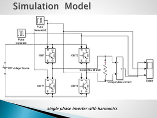
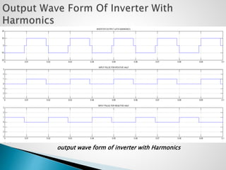
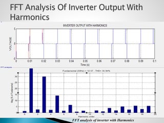
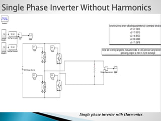
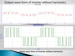
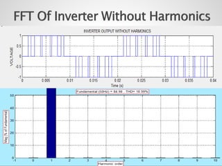
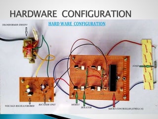
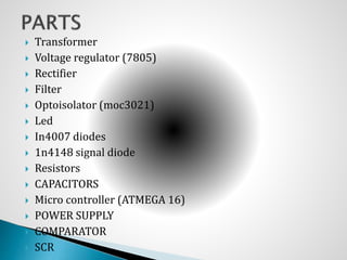
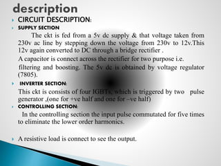
 Introduction
 Brief literature review
 Single phase inverter
 PWM Technique
 Harmonics
 Cause of harmonics
 Simulation model design
 Output of voltage
 Harmonic analysis
 Hardware Configuration
 Conclusion and future work
 References
 The term harmonics referred to Power quality in
ideal world would mean how pure the voltage is, in
its sinusoidal form. In today’s world, prime
importance is given by the engineers to derive a
method to reduce the harmonic
 This project explains the effects of Harmonics in the
Power System and steps to reduce the effects of
Harmonics.
 This project also explains different types of
inverters that are used in the Power System. During
the transformation from DC to AC, harmonics affect
the the power quality a lot
 A device that converts DC power into AC power at
desired output voltage and frequency is called an
Inverter
 Inverters can be broadly classified into two types
based on their operation:
• Voltage Source Inverters (VSI)
• Current Source Inverters (CSI)
 Voltage Source Inverters is one in which the
DC source has small or negligible impedance.
 In other words VSI has stiff DC voltage source
at its input terminals.
 A current source inverter is fed with adjustable
current from a DC source of high impedance
 i.e. from a stiff DC current source. In a CSI fed with
stiff current source
 From view point of connections of semiconductor
devices, inverters are classified as under
• Bridge Inverters
• Series Inverters
• Parallel Inverters
 DC POWER SOURCE UTILIZATION
 UNINTERRUPTIBLE POWER SUPPLIES
 INDUCTION HEATING
 HVDC POWER TRANSMISSION
 VARIABLE-FREQUENCY DRIVES
 ELECTRIC VEHICLE DRIVES
 Pulse width modulation (PWM) is a powerful technique for
controlling analog circuits with a processor's digital
outputs specially used like ranging from measurement and
communications to power control and conversion.
 PWM provides a way to decrease the Total Harmonic
Distortion (THD)
 The THD requirement can be met more easily when the
output of PWM inverter is filtering
 The unfiltered PWM output will have a relatively high THD
 Harmonics provides a mathematical analysis of distortions
to a current or voltage waveform.
 Based on Fourier series Harmonics can describe any
periodic wave as summation of simple sinusoidal waves
which are integer multiples of the fundamental frequency
 If the fundamental frequency is f, the harmonics have
frequencies 2f, 3f, 4f, . . . etc. The harmonics have the
property that they are all periodic at the fundamental
frequency, therefore the sum of harmonics is also periodic
at that frequency
 Harmonics are steady-state distortions to current and
voltage waves and repeat every cycle
 They are different from transient distortions to power
systems such as spikes, dips and impulses
types of harmonics distortion
 even harmonics
 odd harmonics
 Total harmonics distortion or THD is a common
measurement of the level of harmonic distortion present in
power systems.
 THD is defined as the ratio of total harmonics to the value
at fundamental frequency.
2
1
2
1
2
rms
rmsrms
V
VV
THD


 Harmonics are caused by non-linear loads that is loads that
draw a non- sinusoidal current from a sinusoidal voltage
source.
 Some examples of harmonic producing loads are
 electric arc furnaces
 static VAR compensators
 Inverters
 DC converters
 switch-mode power supplies
 and AC or DC motor drives.
single phase inverter with harmonics
output wave form of inverter with Harmonics
FFT analysis of inverter with Harmonics
Single phase inverter with Harmonics
output wave form of inverter without harmonics
 Transformer
 Voltage regulator (7805)
 Rectifier
 Filter
 Optoisolator (moc3021)
 Led
 In4007 diodes
 1n4148 signal diode
 Resistors
 CAPACITORS
 Micro controller (ATMEGA 16)
 POWER SUPPLY
 COMPARATOR
 SCR
 CIRCUIT DESCRIPTION:
 SUPPLY SECTION
The ckt is fed from a 5v dc supply & that voltage taken from
230v ac line by stepping down the voltage from 230v to 12v.This
12v again converted to DC through a bridge rectifier .
A capacitor is connect across the rectifier for two purpose i.e.
filtering and boosting. The 5v dc is obtained by voltage regulator
(7805).
 INVERTER SECTION:
This ckt is consists of four IGBTs, which is triggered by two pulse
generator ,(one for +ve half and one for –ve half)
 CONTROLLING SECTION:
In the controlling section the input pulse commutated for five times
to eliminate the lower order harmonics.
 A resistive load is connect to see the output.
 This project Report deals with the Harmonic analysis
of Single Phase inverter with Pulse Width Modulation
(PWM).
 It includes both simple and practical inverter.
 The Simulink model for both simple and practical
inverter has been simulated in MATLAB.
 Its various parameters such as R,C and Filter design.
These parameters are varied and the resulting voltage
and current graphs has been studied.
 The future work includes improving the stability of
the system and also to study various instability in
SPWM with harmonic analysis in Three phase and
ways to eliminate it and to design an actual
household SPWM-VSI with a better controller
design.
 [1] G John Olav G jaever Tande, “Grid Connection of Deep Sea Wind Farms –
Option s and Challenges”, SINTEF Energy research, www.we-at-a.org/docs/sessie
3_ tande deep sea grid iea annex23.pdf, accessed on May 8, 2008.
 [2] W.Lu and B.T.Ooi,”Multiterminal LVDC system for optimal acquisition of
power in wind farm using induction generators,” IEEE Trans. Power Electron.,vol.
17 no. 4 , pp. 558-563,jul 2002.
 [3] W.Lu and B.T.Ooi,”Optimal acquisition and aggregation of off-shore wind
power by multi terminalvoltage-source hvdc.” IEEE Trans. Power Del., vol. 18, no.
1, pp. 201-206, Jan 2003.
 [4] W.Lu and B.T.Ooi,”Multiterminal HVDC as enabling Technology of premium
quality park,” IEEE Trans. Power Del., vol. 18, no. 3, pp. 915-920, jul 2003.
 [5] J.C.Ciezki and R.W.Ashton,”Selection and stability issues associated with a
navy shipboard and DC zonal electric distribution.” IEEE Trans. Power Del., vol.
15, no. 2, pp. 665-669, Apr 2000.
 [6] Hegi, M.Bahrman, G.Scott, and G.Liss, “Control of Quebec-New England Multi
Terminal HVDC system,” CIGRE Paper 14-04, Paris 1988.
 [7] B. Andersen, L. Xu, P. Horton, and P. Cartwright, “Topologies for VSC
transmission,” Power Engineering Journal, vol. 16, no. 3, pp. 142–150, June 2002.
 [8] P. F. de Toledo, “Feasibility of HVDC for city infeed,” Royal Institute of
Technology, Stockholm, Sweden, Licentiate Thesis, 2003.
 [9] H. Jiang and °A. Ekstr¨om, “Multiterminal HVDC systems in urban areas of
large cities,” IEEE Trans. Power Delivery, vol. 13, no. 4, pp. 1278 – 1284, October
1998.
 [10] X.-P. Zhang, “Multiterminal voltage-sourced converter-based HVDC models
for power flow analysis,” IEEE Trans. Power Syst., vol. 19, no. 4, pp. 1877–1884,
November 2004.
 [11].Roger C. Dugan, Mark F. McGranaghan, H. Wayne Beaty : Electrical Power
Systems quality. New York : McGraw Hill, c1996
 [12].J. Arrillaga, N.R. Watson, S. Chen: Power System Quality Assessment. New
York : John Wiley, c2000
 [13].Ewald F. Fuchs, Mohammad A. S. Masoum : Power Quality in Power Systems
and Electrical Machines. Elsevier Academic Press, c2008
 [14].Wilson E. Kazibwe and Mucoke H. Senduala : Electric Power Quality Control
Techniques. New York: Van Nostrand Reinhold, c1993
 [15].Elias M. Stein, Timonthy S. Murphy : Harmonic Analysis: Real-Variable
Methods, Orthogonality and Oscillatory Integrals. Princeton, N.J.: Princeton
University Press, c1993.
 [16].Issa Batarseh : Power Electronic Circuits. New York : John Wiley, c2004
 Leonard L. Grigsby : Power Systems. CRC Press, c2007
 [17].J. Arrillaga, N. R. Watson : Power System Harmonics. New York: John Wiley,
c2003
 [18].An application of PSO technique for harmonic elimination in a PWM inverter
from World Wide Web
 http://www.sciencedirect.com/science?_ob=ArticleURL&_udi=B6W86-4WGK6J4-
4&_user=10&_rdoc=1&_fmt=&_orig=search&_sort=d&_docanchor=&view=c&_se
archStrId=1114896328&_rerunOrigin=google&_acct=C000050221&_version=1&
_urlVersion=0&_userid=10&md5=d9e37378c6181659a1d2856fabb00184
Harmonics analysis of single phase inverter

Harmonics analysis of single phase inverter

  • 2.
     Introduction  Briefliterature review  Single phase inverter  PWM Technique  Harmonics  Cause of harmonics  Simulation model design  Output of voltage  Harmonic analysis  Hardware Configuration  Conclusion and future work  References
  • 3.
     The termharmonics referred to Power quality in ideal world would mean how pure the voltage is, in its sinusoidal form. In today’s world, prime importance is given by the engineers to derive a method to reduce the harmonic  This project explains the effects of Harmonics in the Power System and steps to reduce the effects of Harmonics.  This project also explains different types of inverters that are used in the Power System. During the transformation from DC to AC, harmonics affect the the power quality a lot
  • 4.
     A devicethat converts DC power into AC power at desired output voltage and frequency is called an Inverter  Inverters can be broadly classified into two types based on their operation: • Voltage Source Inverters (VSI) • Current Source Inverters (CSI)
  • 5.
     Voltage SourceInverters is one in which the DC source has small or negligible impedance.  In other words VSI has stiff DC voltage source at its input terminals.
  • 6.
     A currentsource inverter is fed with adjustable current from a DC source of high impedance  i.e. from a stiff DC current source. In a CSI fed with stiff current source  From view point of connections of semiconductor devices, inverters are classified as under • Bridge Inverters • Series Inverters • Parallel Inverters
  • 7.
     DC POWERSOURCE UTILIZATION  UNINTERRUPTIBLE POWER SUPPLIES  INDUCTION HEATING  HVDC POWER TRANSMISSION  VARIABLE-FREQUENCY DRIVES  ELECTRIC VEHICLE DRIVES
  • 8.
     Pulse widthmodulation (PWM) is a powerful technique for controlling analog circuits with a processor's digital outputs specially used like ranging from measurement and communications to power control and conversion.  PWM provides a way to decrease the Total Harmonic Distortion (THD)  The THD requirement can be met more easily when the output of PWM inverter is filtering  The unfiltered PWM output will have a relatively high THD
  • 9.
     Harmonics providesa mathematical analysis of distortions to a current or voltage waveform.  Based on Fourier series Harmonics can describe any periodic wave as summation of simple sinusoidal waves which are integer multiples of the fundamental frequency  If the fundamental frequency is f, the harmonics have frequencies 2f, 3f, 4f, . . . etc. The harmonics have the property that they are all periodic at the fundamental frequency, therefore the sum of harmonics is also periodic at that frequency
  • 10.
     Harmonics aresteady-state distortions to current and voltage waves and repeat every cycle  They are different from transient distortions to power systems such as spikes, dips and impulses types of harmonics distortion  even harmonics  odd harmonics
  • 11.
     Total harmonicsdistortion or THD is a common measurement of the level of harmonic distortion present in power systems.  THD is defined as the ratio of total harmonics to the value at fundamental frequency. 2 1 2 1 2 rms rmsrms V VV THD  
  • 12.
     Harmonics arecaused by non-linear loads that is loads that draw a non- sinusoidal current from a sinusoidal voltage source.  Some examples of harmonic producing loads are  electric arc furnaces  static VAR compensators  Inverters  DC converters  switch-mode power supplies  and AC or DC motor drives.
  • 13.
    single phase inverterwith harmonics
  • 14.
    output wave formof inverter with Harmonics
  • 15.
    FFT analysis ofinverter with Harmonics
  • 16.
    Single phase inverterwith Harmonics
  • 17.
    output wave formof inverter without harmonics
  • 20.
     Transformer  Voltageregulator (7805)  Rectifier  Filter  Optoisolator (moc3021)  Led  In4007 diodes  1n4148 signal diode  Resistors  CAPACITORS  Micro controller (ATMEGA 16)  POWER SUPPLY  COMPARATOR  SCR
  • 21.
     CIRCUIT DESCRIPTION: SUPPLY SECTION The ckt is fed from a 5v dc supply & that voltage taken from 230v ac line by stepping down the voltage from 230v to 12v.This 12v again converted to DC through a bridge rectifier . A capacitor is connect across the rectifier for two purpose i.e. filtering and boosting. The 5v dc is obtained by voltage regulator (7805).  INVERTER SECTION: This ckt is consists of four IGBTs, which is triggered by two pulse generator ,(one for +ve half and one for –ve half)  CONTROLLING SECTION: In the controlling section the input pulse commutated for five times to eliminate the lower order harmonics.  A resistive load is connect to see the output.
  • 22.
     This projectReport deals with the Harmonic analysis of Single Phase inverter with Pulse Width Modulation (PWM).  It includes both simple and practical inverter.  The Simulink model for both simple and practical inverter has been simulated in MATLAB.  Its various parameters such as R,C and Filter design. These parameters are varied and the resulting voltage and current graphs has been studied.
  • 23.
     The futurework includes improving the stability of the system and also to study various instability in SPWM with harmonic analysis in Three phase and ways to eliminate it and to design an actual household SPWM-VSI with a better controller design.
  • 24.
     [1] GJohn Olav G jaever Tande, “Grid Connection of Deep Sea Wind Farms – Option s and Challenges”, SINTEF Energy research, www.we-at-a.org/docs/sessie 3_ tande deep sea grid iea annex23.pdf, accessed on May 8, 2008.  [2] W.Lu and B.T.Ooi,”Multiterminal LVDC system for optimal acquisition of power in wind farm using induction generators,” IEEE Trans. Power Electron.,vol. 17 no. 4 , pp. 558-563,jul 2002.  [3] W.Lu and B.T.Ooi,”Optimal acquisition and aggregation of off-shore wind power by multi terminalvoltage-source hvdc.” IEEE Trans. Power Del., vol. 18, no. 1, pp. 201-206, Jan 2003.  [4] W.Lu and B.T.Ooi,”Multiterminal HVDC as enabling Technology of premium quality park,” IEEE Trans. Power Del., vol. 18, no. 3, pp. 915-920, jul 2003.  [5] J.C.Ciezki and R.W.Ashton,”Selection and stability issues associated with a navy shipboard and DC zonal electric distribution.” IEEE Trans. Power Del., vol. 15, no. 2, pp. 665-669, Apr 2000.  [6] Hegi, M.Bahrman, G.Scott, and G.Liss, “Control of Quebec-New England Multi Terminal HVDC system,” CIGRE Paper 14-04, Paris 1988.  [7] B. Andersen, L. Xu, P. Horton, and P. Cartwright, “Topologies for VSC transmission,” Power Engineering Journal, vol. 16, no. 3, pp. 142–150, June 2002.  [8] P. F. de Toledo, “Feasibility of HVDC for city infeed,” Royal Institute of Technology, Stockholm, Sweden, Licentiate Thesis, 2003.  [9] H. Jiang and °A. Ekstr¨om, “Multiterminal HVDC systems in urban areas of large cities,” IEEE Trans. Power Delivery, vol. 13, no. 4, pp. 1278 – 1284, October 1998.
  • 25.
     [10] X.-P.Zhang, “Multiterminal voltage-sourced converter-based HVDC models for power flow analysis,” IEEE Trans. Power Syst., vol. 19, no. 4, pp. 1877–1884, November 2004.  [11].Roger C. Dugan, Mark F. McGranaghan, H. Wayne Beaty : Electrical Power Systems quality. New York : McGraw Hill, c1996  [12].J. Arrillaga, N.R. Watson, S. Chen: Power System Quality Assessment. New York : John Wiley, c2000  [13].Ewald F. Fuchs, Mohammad A. S. Masoum : Power Quality in Power Systems and Electrical Machines. Elsevier Academic Press, c2008  [14].Wilson E. Kazibwe and Mucoke H. Senduala : Electric Power Quality Control Techniques. New York: Van Nostrand Reinhold, c1993  [15].Elias M. Stein, Timonthy S. Murphy : Harmonic Analysis: Real-Variable Methods, Orthogonality and Oscillatory Integrals. Princeton, N.J.: Princeton University Press, c1993.  [16].Issa Batarseh : Power Electronic Circuits. New York : John Wiley, c2004  Leonard L. Grigsby : Power Systems. CRC Press, c2007  [17].J. Arrillaga, N. R. Watson : Power System Harmonics. New York: John Wiley, c2003  [18].An application of PSO technique for harmonic elimination in a PWM inverter from World Wide Web  http://www.sciencedirect.com/science?_ob=ArticleURL&_udi=B6W86-4WGK6J4- 4&_user=10&_rdoc=1&_fmt=&_orig=search&_sort=d&_docanchor=&view=c&_se archStrId=1114896328&_rerunOrigin=google&_acct=C000050221&_version=1& _urlVersion=0&_userid=10&md5=d9e37378c6181659a1d2856fabb00184