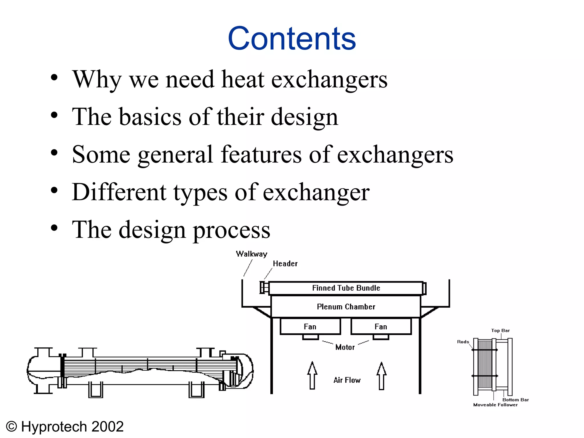
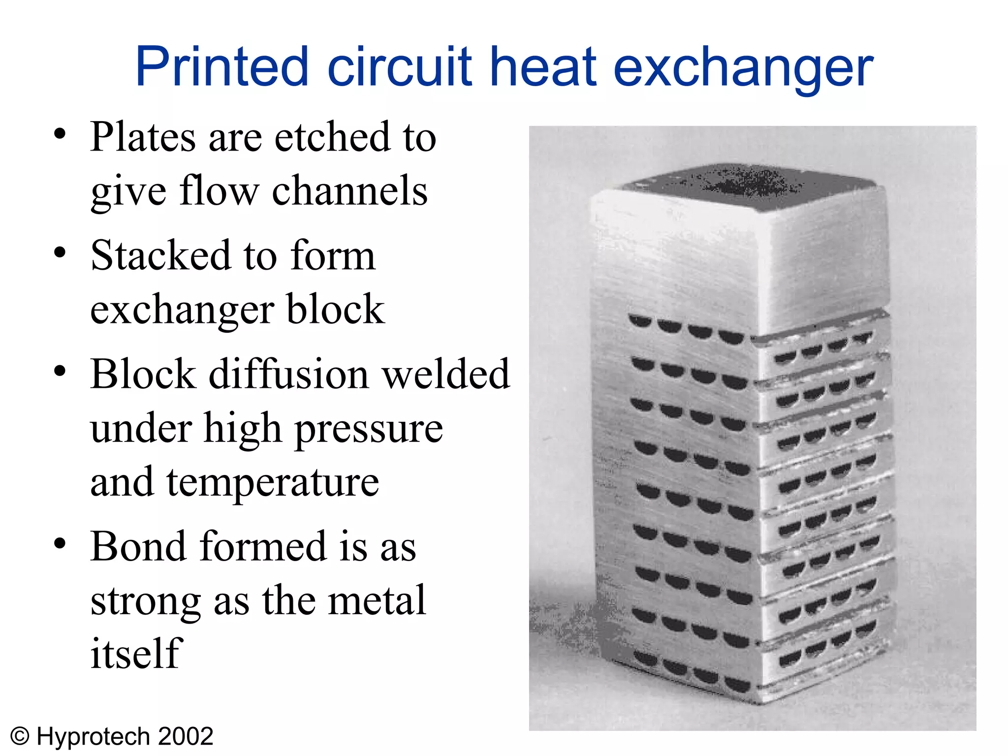
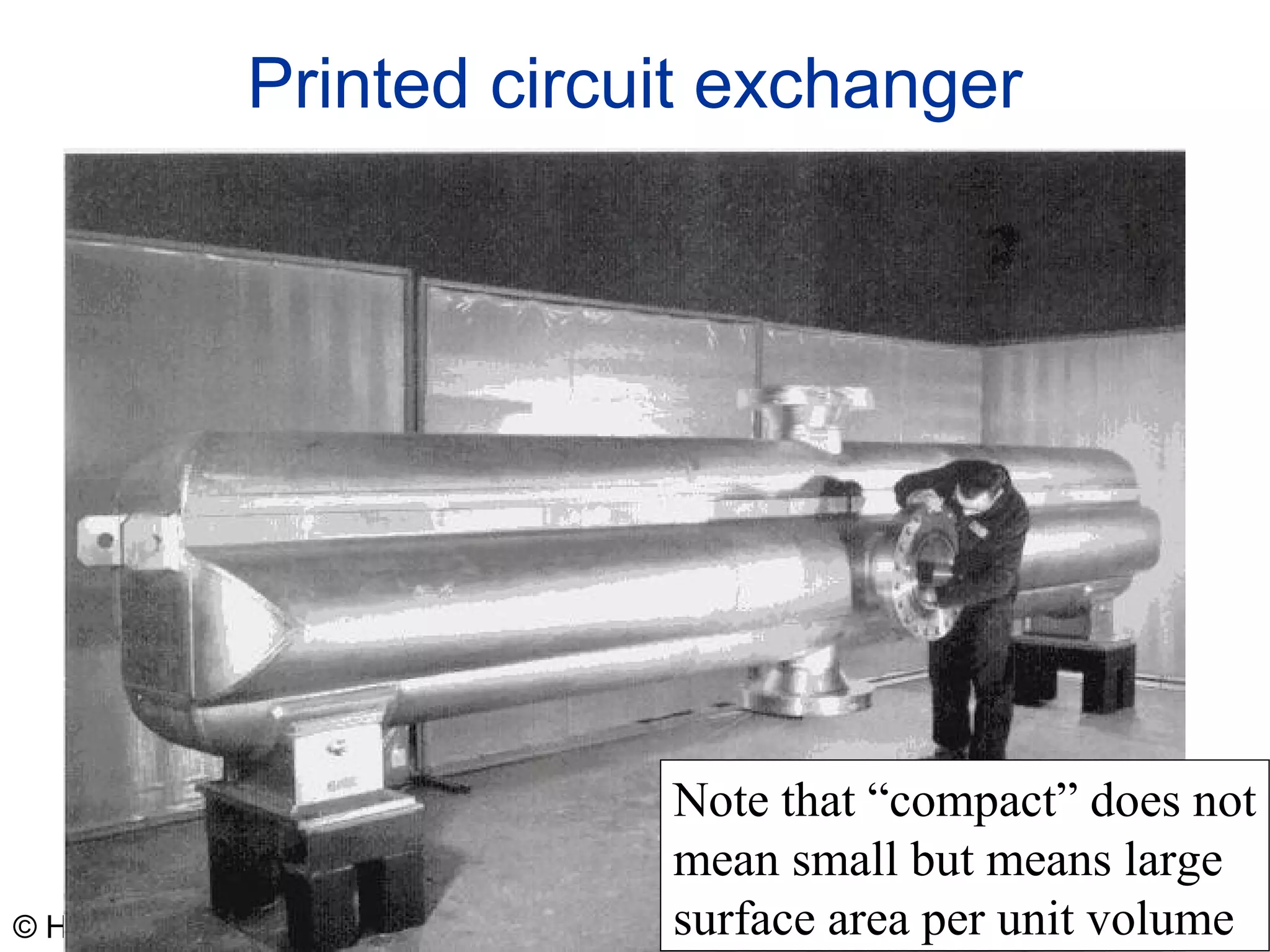
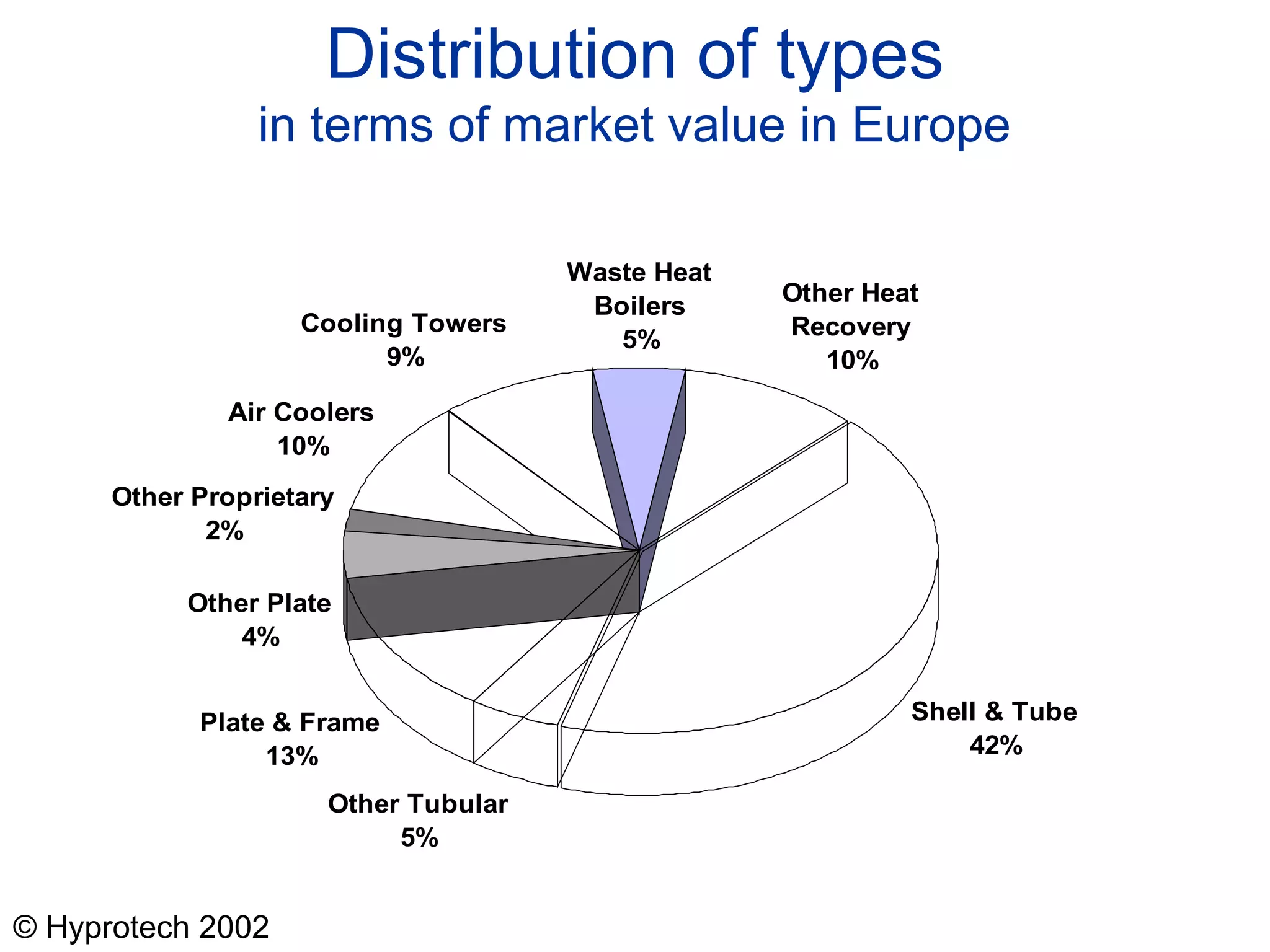
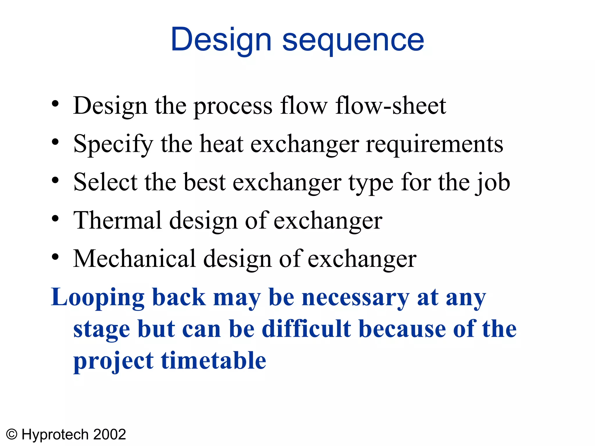
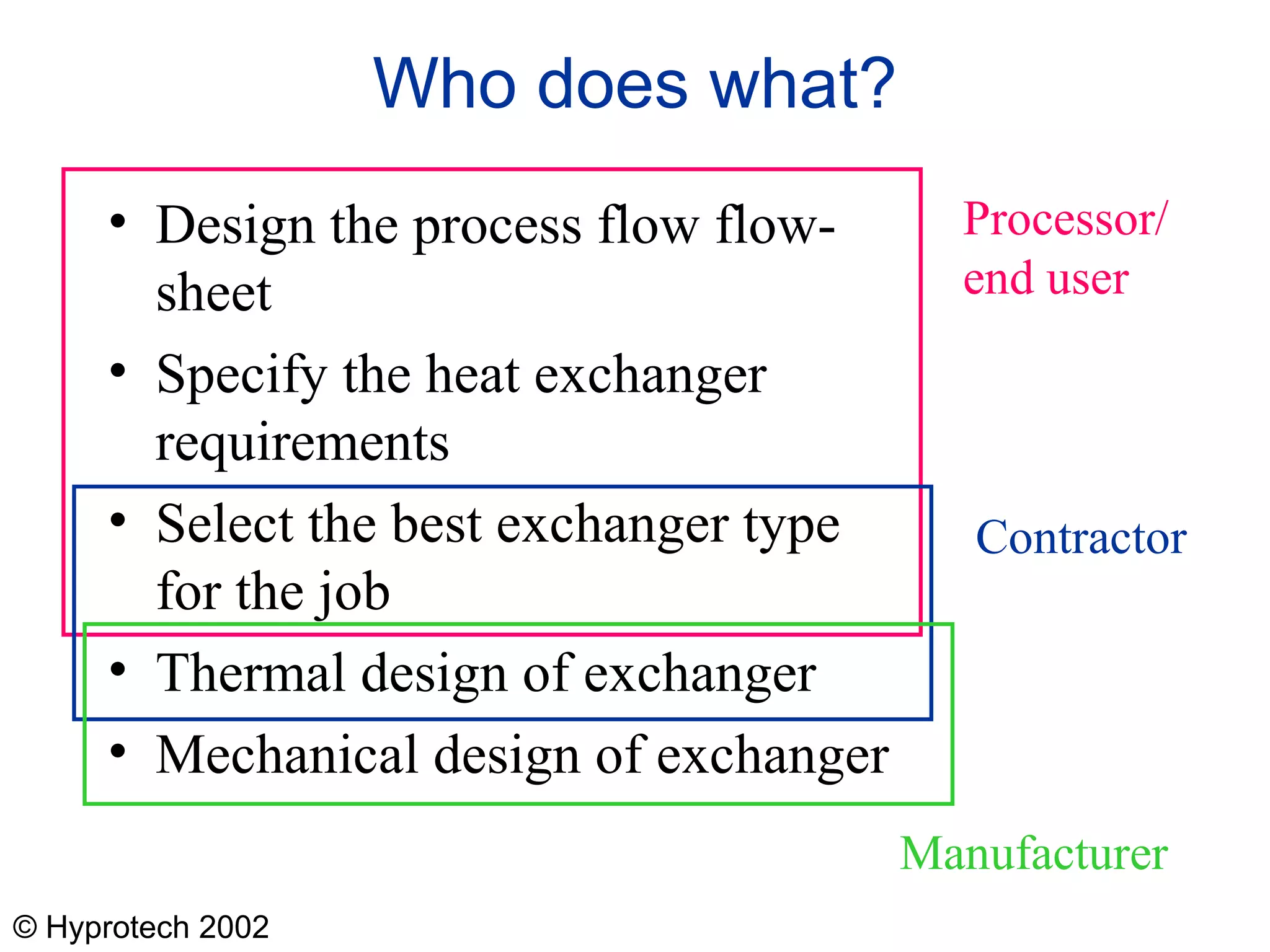
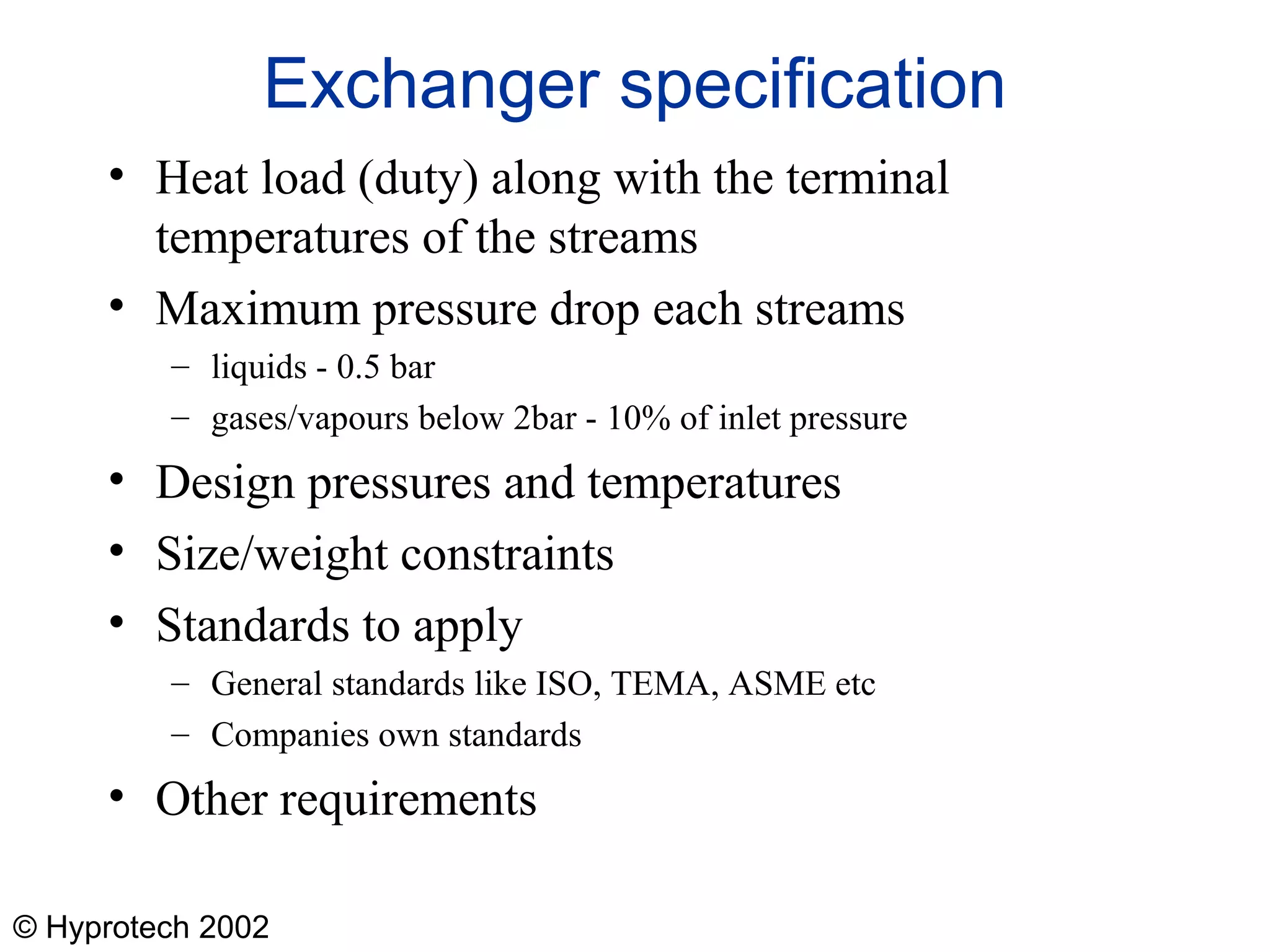
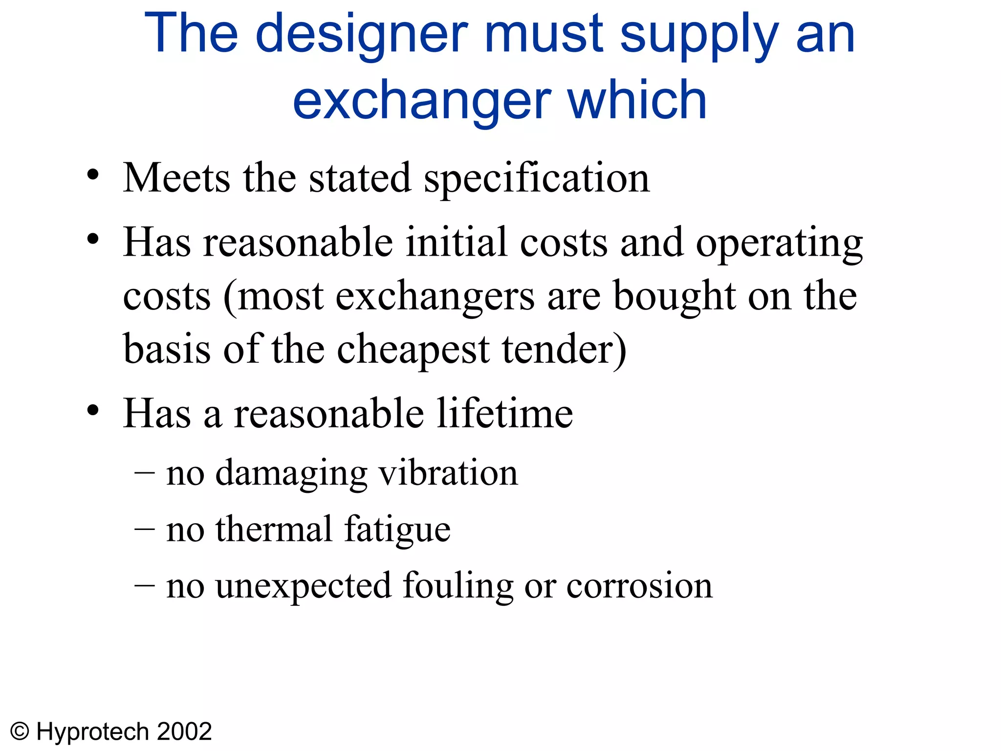
This first lecture is mainly qualitative as a lead in to the later lectures.
It is very helpful to obtain samples from exchanger manufacturers to show the students. Possibilities are
A small, chevron-type plate for a plate and frame exchanger
Various fin types for a plate-fin exchanger
Etched plates and a sample block for a plate of a printed-circuit exchanger
High-finned tube of the type used in air-cooled heat exchangers
Samples of fins used in plate-fin exchangers
Copyright
Hyprotech UK Ltd holds the copyright to these lectures. Lecturers have permission to use the slides and other documents in their lectures and in handouts to students provided that they give full acknowledgement to Hyprotech. The information must not be incorporated into any publication without the written permission of Hyprotech.
Exchanger from Motherwell Bridge Thermal, Scotland
Picture just to introduce a real exchanger early on.
Worth emphasising on this case that the feed-effluent exchanger needs a temperature difference to drive it, so there is a limit to what can be removed by the heat recovery exchanger exchanger. Typically. Feed-effluent exchangers involve a number of exchangers in series so that the picture is a simple case.
This illustrates that real flow-sheets are much more complicated than the idealised cases shown previously. The many exchangers are to heat up streams to the required temperature for distillation. The main heat input is from the furnace or fired heater shown. Also, as much heat as possible is recovered when the refined streams are cooled down. As if this were not complicated enough, many of the exchangers shown would actually be groups of exchangers.
There, in practice, many more heat exchangers in a real plant.
The refinery example shown previously, the hot utility is the furnace.
It is worth mentioning that the log mean becomes the arithmetic mean when the two end temperature differences become the same.
Students could try the derivation. The starting point is a simple change of variables. Given that T varies as a straight line with Q, the equation from the last slide may be rewritten as
It should be stressed that modern design software does not use these correction factors because their derivation involves too many assumptions that are not realised in practice. In stead, modern software carries out numerical intigrateions to obtain the results.
There are two values of depending on which stream is taken as stream 1. We are concerned with the higher of the two in this lecture series.
The human lung is included to put mans designs into the context of what nature achieves. However, our lungs are mainly mass transfer devices which transfers oxygen to the blood and removes carbon dioxide. Nevertheless, the lungs have an important heat transfer function. The air we breath in is relatively cold and must be heated to blood heat before making close contact with the blood. The air is therefore heated as it is taken in, thus cooling the various passage ways through which it flows. These passage ways are reheated as we breath out the stale air. The is a form of “regenerative heat exchanger”.
The case of recuperators with the wall separating the streams is highlighted. It is the most important and the main subject of these lectures.
As has been noted, the human lung acts as a regenerator because the cold stream (the incoming air) passes through the same passages as the hot stream (the outgoing stale air).
The regenerator shown above is a heat wheel.
Photograph from APV
Forced draught most common because it is easier then to service the fan motor and also the fan motor runs cooler
Picture from Motherwell Bridge Thermal
Figure shows a number of interesting points
The way headers are arranged
The way gaps are left at appropriate places to allow flow between the layer and the header
The use of low frequency finning to distribute the flow across the channel
Photograph from Chart Heat Exchangers Ltd
Photograph from Heatric Ltd
This is for a wide range of industrial heat exchangers. If we look at chemical and refinery applications, the shell and tube type predominates (see lecture 3).