This document provides information on different types of heat exchangers:
- Multiple pass heat exchangers allow fluids to pass each other more than once using U-bend tubes or shell-side baffles, improving heat transfer.
- Plate heat exchangers use corrugated metal plates separated by gaskets to transfer heat between fluids in alternating channels. They are compact and efficient.
- Scraped surface heat exchangers have an internal rotating cylinder fitted with blades that continuously scrape the heating surface, used for viscous fluids.
- Double pipe heat exchangers consist of two concentric pipes for countercurrent flow, used in boilers, coolers, condensers and evaporators.
basic of extrusion; type of extruder; extruded producrs; cold extrusion & hot...PulkitTyagi16
basic of extrusion, gives you a good idea about extrusion and extruded products. it has essential information regarding kurkure, macroni products, chewing products and extruded pet products. hard boiled sweets and are also made by extrusion
The preservation of food by freezing has become a major industry.Preservation of a food by freezing occurs by several mechanisms. At
temperatures below 0°C there is a significant reduction in growth
rates for microorganisms and in the corresponding deterioration of
the product due to microbial activity.
Several freezing systems for food operate with direct contact between
the refrigerant and the product.
cryogenic freezer is direct contact freezer.
Food extrusion is a form of extrusion used in food processing. It is a process by which a set of mixed ingredients are forced through an opening in a perforated plate or die with a design specific to the food, and is then cut to a specified size by blades.
HEAT EXCHANGERS. Heat exchangers are devices that facilitate the exchange of heat between two fluids that are at different temperature while keeping them from mixing with each other.
2. Double Pipe Heat Exchangers
3. A typical double pipe heat exchanger basically consists of a tube or pipe fixed concentrically inside a larger pipe or tube They are used when flow rates of the fluids and the heat duty are small (less than 5 kW) These are simple to construct, but may require a lot of physical space to achieve the desired heat transfer area.
4. Double-pipe exchangers is the generic term covering a range of jacketed 'U' tube exchangers normally operating in countercurrent flow of two types which is true double pipes and multitubular hairpins. One fluid flows through the smaller pipe while the other fluid flows through the annular space between the two pipes. Two types of flow arrangement: Parallel flow Counter flow
5. • The fluids may be separated by a plane wall but more commonly by a concentric tube (double pipe) arrangement shown in fig. If both the fluids move in the same direction, the arrangement is called a parallel flow type. In the counter flow arrangement the fluids move in parallel but opposite directions. In a double pipe heat exchanger, either the hot or cold fluid occupies the annular space and the other fluid moves through the inner pipe. The method of solving the problem using logarithmic mean temperature difference is typical and more iteration must be done. So it takes more time for the problem to solve. Therefore another method is practiced for solving this type of problems. This method is known as Effectiveness and Number of Transfer Units or simply ε-NTU method.“Effectiveness of heat exchangers is defined as actual heat transfer rate by maximum possible heat transfer rate”.The LMTD method may be applied to design problems for which the fluid flow rates and inlet temperatures, as well as a desired outlet temperature, are prescribed.
6. Application of Double Pipe Heat Exchanger Pasteurization or sterilization of food and bioproducts Condensers and evaporators of air conditioners Radiators for internal combustion engines Charge air coolers and intercoolers for cooling supercharged engine intake air of diesel engines.
• Types of heat exchangers
• Classification of heat exchangers
• components of heat exchanger
• Materials of heat exchanger
• troubleshooting of heat exchanger
Type of heat exchanger. Which is mainly used in food industries, like dairy plant, for the pasturization, heat treatment of the beavrages or liquid raw material.
Key Features of The Italian Restaurants.pdfmenafilo317
Filomena, a renowned Italian restaurant, is renowned for its authentic cuisine, warm environment, and exceptional service. Recognized for its homemade pasta, traditional dishes, and extensive wine selection, we provide a true taste of Italy. Its commitment to quality ingredients and classic recipes has made it a adored dining destination for Italian food enthusiasts.
Piccola Cucina is regarded as the best restaurant in Brooklyn and as the best Italian restaurant in NYC. We offer authentic Italian cuisine with a Sicilian touch that elevates the entire fine dining experience. We’re the first result when someone searches for where to eat in Brooklyn or the best restaurant near me.
At Taste Of Middle East, we believe that food is not just about satisfying hunger, it's about experiencing different cultures and traditions. Our restaurant concept is based on selecting famous dishes from Iran, Turkey, Afghanistan, and other Arabic countries to give our customers an authentic taste of the Middle East
Ang Chong Yi Navigating Singaporean Flavors: A Journey from Cultural Heritage...Ang Chong Yi
In the heart of Singapore, where tradition meets modernity, He embarks on a culinary adventure that transcends borders. His mission? Ang Chong Yi Exploring the Cultural Heritage and Identity in Singaporean Cuisine. To explore the rich tapestry of flavours that define Singaporean cuisine while embracing innovative plant-based approaches. Join us as we follow his footsteps through bustling markets, hidden hawker stalls, and vibrant street corners.
Roti Bank Hyderabad: A Beacon of Hope and NourishmentRoti Bank
One of the top cities of India, Hyderabad is the capital of Telangana and home to some of the biggest companies. But the other aspect of the city is a huge chunk of population that is even deprived of the food and shelter. There are many people in Hyderabad that are not having access to
1. a. Write short notes on : multiple pass heat exchangers
Plate heat exchangers
Scrapped surface heat exchangers
Double pipe heat exchangers
Tubular heat exchangers
b. Differentiate between : Contact type and non-contact heat exchangers
Co-current and counter-current flow in heat exchangers
Question 1: Write notes on heat exchangers
A heat exchanger is a device built for efficient heat transfer from one medium to another, whether
the media are separated by a solid wall so that they never mix, or the media are in direct contact.
Typical applications involve heating or cooling of a fluid stream of concern and evaporation or
condensation of single- or multicomponent fluid streams. In a heat exchanger there is no direct
contact between the two fluids. The heat is transferred from the hot fluid to the metal isolating the
two fluids and then to the cooler fluid.
In other applications, the objective may be to recover or reject heat, or sterilize, pasteurize,
fractionate, distill, concentrate, crystallize, or control a process fluid. They are widely used in
Space Heating, Refrigeration, Air Conditioning, Power Plants, Chemical Plants, Petro-chemical
Plants, Petroleum Refineries, and Natural Gas Processing. One common example of a heat
exchanger is the Radiator in a car.
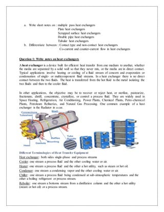
Different Terminologies of Heat Transfer Equipment
Heat exchanger: both sides single-phase and process streams
Cooler: one stream a process fluid and the other cooling water or air.
Heater: one stream a process fluid and the other a hot utility, such as steam or hot oil.
Condenser: one stream a condensing vapor and the other cooling water or air.
Chiller: one stream a process fluid being condensed at sub-atmospheric temperatures and the
other a boiling refrigerant or process stream.
Reboiler: one stream a bottoms stream from a distillation column and the other a hot utility
(steam or hot oil) or a process stream.
2. a. Multiple pass heat exchangers
If fluids pass each other more than once then it applies the principle of multiple pass heat
exchangers .Reverse flow are common in these heat exchanger as there are designed with “U”
bend tubes. These tubes provide a pathway for back and forth movement of fluid across the length
of the heat exchanger. Another way for establishing a multiple pass is to insert baffles on the shell
side of the heat exchanger. Baffles directs shell sides the fluid back and forth across the tubes to
achieve multiple pass effect. Tubes are sometimes arrayed within the shell in order to shorten the
overall exchanger length of the heat exchanger in the opposite direction using the other half of the
tube bundle. The exchanger would then be said to have two side tube passes. It has an advantage
that the tube side velocities are doubled for the same flow rate thus the heat transfer coefficient
increases. Longitudinal baffles are placed in the shell such that the number of shell sides passes
can be increased and a shell side coefficient increase consequently. The more complex and costly,
the more complex and costly construction and the higher pressure drops for each fluid is off set of
multiple pass heat exchanger.
3. Advantages of Multiple Pass Heat Exchangers
It has wide ranges of pressure thus pressure can be varied over large drops
Thermal stresses can be accommodated inexpensively.
Use of materials is diverse and it take into consideration corrosion and other disruptive
concerns .shell and tubes can be made with different material.
Extended heat transfer surfaces can be used to enhance heat transfer.
Cleaning and repair are relatively straightforward, because the equipment can be
dismantled for this purpose
b. Plate heat exchangers
It’s a type of Heat Exchanger which consists of many corrugated stainless-steel sheets
separated by polymer gaskets and clamped into a steel frame.Plate heat exchangers transfer
heat by placing thin, corrugated metal sheets side by side and connecting them by gaskets.
Flow of the substances to be heated and cooled takes place between alternating sheets
allowing heat to transfer through the metal sheets.
The parts and function
The heat exchangers frame is made up of thick steel pressure retaining parts, the fixed cover and
the movable cover, that when pulled together with the tightening bolts form the pressure retaining
structure for the plates / plate pack. The carrying bar and guide bar act as a carrier and guide to
both the plates and the movable cover. The heat exchanger plates, which make up the heat
transfer surface, are clamped between two plates of steel with the use of the tightening bolts. The
heat exchanger construction allows a plate heat exchanger to be easily opened for inspection and
cleaning. Each plate has a gasket that produces a sealing and channel system through the entire
plate pack in which the two heat exchanging media flow in a counter-current direction. The circular
portion of the gasket stops the fluid from going across the heat transfer plate and sends it to the
next open channel. The remaining portion or field gasket directs the opposing fluid across the heat
transfer surface. The heat transfer plates with gaskets are arranged in an alternating pattern of
left hand flow and right hand flow to direct the fluids in an opposing direction within the heat
exchanger. The completed assembly of all the plates and gaskets is called the “plate pack.”
4. Plate heat exchangers are used because there have high heat transfer area, high heat transfer
coefficient. There are compact and have lower floor space requirements. By increasing the
number of plates the area of heat exchange can be increased. They are most suitable type heat
exchangers for lower flow rates and heat sensitive substances. They can perform multiple
duties that can be performed by a single unit. There are classified into gasketed plate heat
exchanger, brazed plate heat exchanger, welded plate heat exchangers.
Benefits of plate heat exchangers are lightweight: The PHE unit is lighter in total weight
than other types of heat exchangers because of reduced liquid volume space and less surface
area for a given application. High-viscosity applications: Because the PHE induces turbulence
at low fluid velocities, it has practical application for high-viscosity fluids. Saves space and
servicing time: The PHE fits into an area one-fifth to one-half of that required for a comparable
shell and tube heat exchanger. The PHE can be opened for inspection, maintenance. Lower
liquid volume: Since the gap between the heat transfer plates is relatively small, a PHE
contains only low quantities of process fluids. The benefit is reduced cost due
to lower volume .Lower cost: PHEs are generally more economical than other
types of equivalent duty heat exchangers due to the higher thermal efficiency and lower
manufacturing costs. Quick process control: Owing to the thin channels created between the
two adjacent plates, the volume of fluid contained in PHE is small; it quickly reacts to the new
process condition and is thereby easier to control.
The limitations of plate heat exchangers are the maximum allowable working pressure is
also limited by the frame strength and plate deformation resistance. Commonly stated limits
have been 300°F (149°C) and 300 psi .Because of the narrow gap between the plates, high
liquid rates will involve excessive pressure drops, thus limiting the capacity. Large differences
in fluid flow rates of two streams cannot be handled. The gaskets cannot handle corrosive or
aggressive media. Gaskets always increase the leakage risk. The standard PHEs cannot handle
particulates that are larger than 0.5 mm.
In conclusion Plate heat exchangers are available in a wide variety of configurations to suit
most processes heat transfer requirements. The advantages of PHEs, and associated heat
transfer enhancement techniques, extend far beyond energy efficiency. Lower capital cost,
reduced plant size, and increased safety are typical of the benefits arising from the use of PHEs.
Plate heat exchangers can replace some normal size heat exchangers bringing advantages and
performance
c. Scraped surface heat exchangers
One type of heat exchanger, that finds considerable use in the food processing industry
particularly for products of higher viscosity, consists of a jacketed cylinder with an internal
cylinder concentric to the first and fitted with scraper blades. The blades rotate, causing the
fluid to flow through the annular space between the cylinders with the outer heat transfer
surface constantly scraped. Coefficients of heat transfer vary with speeds of rotation but
they are of the order of 900-4000 J m-2 s-1 °C-1. These machines are used in the freezing of
ice cream and in the cooling of fats during margarine manufacture. Liquid foods that
contain large solid particles are heated in scraped-surface heat exchangers. These heat
exchangers use blades to continuously scrape the inside surface of the heating chamber.
5. The scraping action protects highly viscous foods from being burned on the heating
surface.
The dynamic scraped surface heat exchanger (DSSHE) was designed to face some problems
found in other types of heat exchangers. They increase heat transfer by:
o removing the fouling layers,
o increasing turbulence in case of high viscosity flow,
o Avoiding the generation of ice and other process by-products.
The dynamic scraped surface heat exchangers incorporate an internal mechanism which
periodically removes the product from the heat transfer wall. The product side is scraped by blades
attached to a moving shaft or frame. The blades are made of a rigid plastic material to prevent
damage to the scraped surface. This material is FDA approved in the case of food applications.
d. Double pipe heat exchangers
Two sets of concentric pipes, two connecting tees, and a return head and a return bend. A device
whose purpose is the transfer of thermal energy between two fluids. Common applications: boilers,
coolers, condensers, evaporators. Common design consists of tow fluids separated by a conducting
medium.
Simplest type has one tube inside another - inner tube may have longitudinal fins on the outside
However, most have a number of tubes in the outer tube - can have very many tubes thus
becoming a shell-and-tube.
6. Advantages of Double Pipe Heat Exchangers
1. Double pipe heat exchanger consists of two concentric pipes are hot fluid, cold fluid.
2. Economically adaptable to service differentials. Ideal for wide temperature ranges and
differentials.
3. Provides shorter deliveries than shell and tube due to standardization of design and
construction.
4. Operates in true counter current flow permitting extreme temperature cross.
e. Tubular heat exchangers
This type of heat exchanger are categorized in following types: Double Pipes heat Exchanger,
Shell & Tube Heat Exchanger, Spiral Heat Exchanger, Cracked Surface Heat Exchanger.
Shell and tube heat exchanger
Shell and tube heat exchangers consist of a series of tubes. One set of these tubes contains the fluid
that must be either heated or cooled. The second fluid runs over the tubes that are being heated or
cooled so that it can either provide the heat or absorb the heat required. A set of tubes is called the
tube bundle and can be made up of several types of tubes: plain, longitudinally finned. Shell and
tube heat exchangers are typically used for high-pressure applications (with pressures greater than
30 bar and temperatures greater than 260 °C). This is because the shell and tube heat exchangers
are robust due to their shape. Shell and tube heat exchanger units can be designed for almost all
condition of temperature and pressure. In extreme cases, high pressure may impose a limitation by
fabrication problems associate with material thickness
Double pipe heat exchanger
7. They consist of one pipe concentrically located inside a second larger pipe. In this heat exchanger
the fluid to be cooled or heated passes through the tube 2(green) and the other fluid is passed
through tube 1 (red) to absorb or release the heat.
Advantages: Cheap for both design and maintenance.
Disadvantages: Low efficiency and requires large space.
Mainly used in pasteurization, digester heating, heat recovery, pre-heating, effluent cooling.
Spiral heat exchanger
A spiral heat exchanger (SHE), may refer to a helical (coiled) tube configuration efficient use of
space. They can be easily cleaned.
A Spiral Heat Exchangers (or SHE) is a coiled tube arrangement, with two channels coiled one
around the other. These two channels operate in a counter-flow arrangement, offering excellent
turn down ratios, while optimizing flow patterns which in turn, enhance heat transfer. spiral heat
exchangers are mainly used in pasteurization, recuperators (Exhaust and Air Handling
Systems),sludge treatment (Thermal depolymerisation) Selection of spiral heat exchangers is
based on cost, high/low pressure limits, thermal performance, temperature ranges, product mix
(liquid/liquid, particulates or high-solids liquid),pressure drops across the exchanger, fluid flow
capacity, clean ability, maintenance and repair, materials required for construction, ability and ease
of future expansion Spiral heat exchangers can be used in most applications in the chemical process
industry
In many difficult applications where fouling and plugging are problems, a standard shell and tube
design may not be effective
While a spiral heat exchanger often has a higher initial cost, it may provide a lower life cycle cost
due to lower fouling rates and ease of maintenance
8. Question 2 Contact type and Non-contact type
Contact type
In Direct Contact type of heat Exchanger heat is directly transferred between Hot and Cold fluids.
There is no separating wall between the hot and cold fluids.
Most direct contact heat exchangers fall under the Gas- Liquid category, where heat is transferred
between a gas and liquid in the form of drops, films or sprays.
Properties of both fluids, such as viscosity, thermal conductivity, density, specific heat and reaction
on the metal in contact are essential to determine the pumping, thermal requirement and material
construction.
In a direct-contact exchanger, two fluid streams come into direct contact, exchange heat, and
are then separated.
Common applications of a direct-contact exchanger involve mass transfer in addition to heat
transfer, such as in evaporative cooling and rectification.
However, the applications are limited to those cases where a direct contact of two fluid
streams is permissible.
However direct contact are in three classes
a) Immiscible Fluid Exchangers
b) Gas–Liquid Exchangers
c) Liquid–Vapor Exchangers
Immiscible Fluid Exchangers
In this type, two immiscible fluid streams are brought into direct contact.
These fluids may be single-phase fluids, or they may involve condensation or vaporization.
Condensation of organic vapors and oil vapors with water or air are typical examples.
Gas–Liquid Exchangers
In this type, one fluid is a gas (more commonly, air) and the other a low-pressure liquid (more
commonly, water) and are readily separable after the energy exchange.
In either cooling of liquid (water) or humidification of gas (air) applications, liquid partially
evaporates and the vapor is carried away with the gas.
In these exchangers, more than 90% of the energy transfer is by virtue of mass transfer (due to the
evaporation of the liquid), and convective heat transfer is a minor mechanism.
A ‘‘wet’’ (water) cooling tower with forced- or natural-draft airflow is the most common
application.
Other applications are the air-conditioning spray chamber, spray drier, spray tower, and spray
pond.
Liquid–Vapor Exchangers
In this type, typically steam is partially or fully condensed using cooling water, or water is
heated with waste steam through direct contact in the exchanger.
Noncondensables and residual steam and hot water are the outlet streams.
Common examples are desuperheaters and open feed water heaters (also known as
deaerators) in power plants.
9. Compared to indirect contact recuperators and regenerators, in direct-contact heat exchangers,
1. very high heat transfer rates are achievable,
2. the exchanger construction is relatively inexpensive, and
3. the fouling problem is generally nonexistent, due to the absence of a heat transfer surface
(wall) between the two fluids.
Non-Contact type
In an Indirect Contact Type Heat Exchanger, the fluid stream remains separated. There
is separating wall between the hot and cold fluids.
The heat transfer in this type of heat exchanger takes place continuously through a
dividing wall.
Most indirect contact heat exchangers fall under those gases and liquids that are
soluble in nature.
The fluid streams remain separate and the heat transfers continuously through a
dividing wall into and out of the wall in a transient manner.
Non-contact are in three classes
a) Direct transfer type heat exchanger
b) Storage type heat exchanger
c) Fluidized bed heat exchanger
a) Direct Transfer Type Heat Exchanger
In this, type heat transfers continuously from the
hot fluid to the cold fluid through a dividing wall.
There is no direct mixing of the fluids because
each fluid flows in separate fluid passages.
It is also known as recuperators. Examples,
tubular exchangers, plate and frame heat
exchangers and extended surface exchangers.
Tubular
Exchanger
Plate and Frame
Exchanger
10. b) Storage Type Heat Exchanger (Regenerative Heat Exchanger)
In a storage type exchanger, both fluids flow alternatively through the
same flow passages, and hence heat transfer is intermittent.
The heat transfer surface (or flow passages) is generally cellular in
structure and is referred to as a matrix, or it is a permeable (porous) solid
material, referred to as a packed bed.
When hot gas flows over the heat transfer surface (through flow
passages), the thermal energy from the hot gas is stored in the matrix
wall, and thus the hot gas is being cooled during the matrix heating
period.
As cold gas flows through the same passages later (i.e., during the matrix
cooling period), the matrix wall gives up thermal energy, which is
absorbed by the cold fluid.
Thus, heat is not transferred continuously through the wall as in a direct-
transfer type exchanger (recuperator), but the corresponding thermal
energy is alternately stored and released by the matrix wall.
Fixed Bed Regenerator
11. b) Storage Type Heat Exchanger (Regenerative Heat Exchanger)
a. Regenerative heating was one of the most important technologies
developed during the Industrial Revolution when it was used in the hot
blast process on blast furnaces.
b. It was later used in glass and steel making, to increase the efficiency of
open hearth furnaces, and in high pressure boilers and chemical and other
applications, where it continues to be important today.
c. Fluidized bed heat exchanger
In a fluidized-bed heat exchanger, one side of a two-fluid exchanger is
immersed in a bed of finely divided solid material, such as a tube bundle
immersed in a bed of sand or coal particles. The common applications of
the fluidized-bed heat exchanger are drying, mixing, adsorption, reactor
engineering, coal combustion, and waste heat recovery
Difference between Direct and Indirect Heat Exchanger
Direct Heat Exchanger Indirect Heat Exchanger
Not have a separating wall between two fluids. Have a separating wall between two fluids.
Mostly used for those gases and liquids that are
not soluble in nature
Used for those gases and liquids that are soluble
in nature.
Mostly use drops and steam for heat transfer There is no use of steam and drops
12. Que 2 (ii) Co-current and counter-current flow in heat exchangers
Co-current and countercurrent exchange mechanisms
the magnitude of the property to be exchanged, is represented by shading. The direction of
transfer across the barrier is from the greater to the lesser magnitude.
In the co-current flow exchange mechanism, the two fluids flow in the same direction.
As the Co-current and countercurrent exchange mechanisms diagram showed, a co-current
exchange system has a variable gradient over the length of the exchanger. With equal flows in
the two tubes, this method of exchange is only capable of moving half of the property from one
flow to the other, no matter how long the exchanger is.
If each stream changes its property to be 50% closer to that of the opposite stream's inlet
condition, exchange will stop when the point of equilibrium is reached, and the gradient has
declined to zero. In the case of unequal flows, the equilibrium condition will occur somewhat
closer to the conditions of the stream with the higher flow.
Co-current flow examples
Co-current and Countercurrent heat exchange
A co-current heat exchanger is an example of a co-current flow exchange mechanism.
Two tubes have a liquid flowing in the same direction. One starts off hot at 60 °C, the second
cold at 20 °C. A thermoconductive membrane or an open section allows heat transfer between
the two flows.
13. The hot fluid heats the cold one, and the cold fluid cools down the warm one. The result is
thermal equilibrium: Both fluids end up at around the same temperature: 40 °C, almost exactly
between the two original temperatures (20 and 60 °C). At the input end, there is a large
temperature difference of 40 °C and much heat transfer; at the output end, there is a very small
temperature difference (both are at the same temperature of 40 °C or close to it), and very little
heat transfer if any at all. If the equilibrium—where both tubes are at the same temperature—is
reached before the exit of the liquid from the tubes, no further heat transfer will be achieved
along the remaining length of the tubes.
A similar example is the co-current concentration exchange. The system consists of two tubes,
one with brine (concentrated saltwater), the other with freshwater (which has a low concentration
of salt in it), and a semi permeable membrane which allows only water to pass between the two,
in an osmotic process. Many of the water molecules pass from the freshwater flow in order to
dilute the brine, while the concentration of salt in the freshwater constantly grows (since the salt
is not leaving this flow, while water is). This will continue, until both flows reach a similar
dilution, with a concentration somewhere close to midway between the two original dilutions.
Once that happens, there will be no more flow between the two tubes, since both are at a similar
dilution and there is no more osmotic pressure.
Countercurrent flow
Spiral counter-current heat exchange schematic
In countercurrent flow, the two flows move in opposite directions.
Two tubes have a liquid flowing in opposite directions, transferring a property from one tube to
the other. For example, this could be transferring heat from a hot flow of liquid to a cold one, or
transferring the concentration of a dissolved solute from a high concentration flow of liquid to a
low concentration flow.
The counter-current exchange system can maintain a nearly constant gradient between the two
flows over their entire length of contact. With a sufficiently long length and a sufficiently low
flow rate this can result in almost all of the property transferred. So, for example, in the case of
heat exchange, the exiting liquid will be almost as hot as the original incoming liquid's heat.
Countercurrent flow examples
In a countercurrent heat exchanger, the hot fluid becomes cold, and the cold fluid becomes
hot.
14. In this example, hot water at 60 °C enters the top pipe. It warms water in the bottom pipe which
has been warmed up along the way, to almost 60 °C. A minute but existing heat difference still
exists, and a small amount of heat is transferred, so that the water leaving the bottom pipe is at
close to 60 °C. Because the hot input is at its maximum temperature of 60 °C, and the exiting
water at the bottom pipe is nearly at that temperature but not quite, the water in the top pipe can
warm the one in the bottom pipe to nearly its own temperature. At the cold end—the water exit
from the top pipe, because the cold water entering the bottom pipe is still cold at 20 °C, it can
extract the last of the heat from the now-cooled hot water in the top pipe, bringing its
temperature down nearly to the level of the cold input fluid (21 °C).
The result is that the top pipe which received hot water, now has cold water leaving it at 20 °C,
while the bottom pipe which received cold water, is now emitting hot water at close to 60 °C. In
effect, most of the heat was transferred.
Conditions for higher transfer results
It should be noted that nearly complete transfer in systems implementing countercurrent
exchange, is only possible if the two flows are, in some sense, "equal".
For a maximum transfer of substance concentration, an equal flowrate of solvents and solutions
is required. For maximum heat transfer, the average specific heat capacity and the mass flow rate
must be the same for each stream. If the two flows are not equal, for example if heat is being
transferred from water to air or vice versa, then, similar to co-current exchange systems, a
variation in the gradient is expected because of a buildup of the property not being transferred
properly.
Types of flows in heat exchangers
Co-current flow
where mc – mass flow rate in cold stream
mh – mass flow in hot stream
Countercurrent flow
15. REFERANCES
Berk, Z. (2009). Food Process Engineering & Technology (1st Edition). Elsevier Inc.
Hausbrand, E. (1933) Condensing and Cooling Apparatus, 5th ed, Van Nostrand, New
York.
Heat Exchanger Design Handbook. Kuppan Thulukkanam, CRC Press.
Jacobs, H. R. (1988) Direct Contact Heat Transfer for Process Technologies. ASME
Journal of Heat Transfer, Vol. 110, pp. 1259-1270.
Jacobs, H. R. (1995) Direct Contact Heat Exchangers, Heat Exchanger Design
Handbook.
Jacobs, H. R. (1995) Direct Contact Heat Transfer, Heat Exchanger Design Handbook
Fundamentals of Heat Exchanger Design. Ramesh K. Shah and Dušan P. Sekulic, John
Wiley & Sons, Inc.
Singh, P.R., Heldman, D. R. (2009). Introduction to Food Engineering (4th Edition).
Elsevier Inc.
Smith, P. G. (2011). Introduction to Food Process Engineering. Springer Science &
Business Media
Subramanian, R, S. Thermal Analysis of a Steady State Heat Exchanger. Department of
Chemical and Bimolecular Engineering Clarkson University Journal.
Toledo, R. T. (2007). Fundamentals of Food Process Engineering. (3rd Edition). Springer
Science Business Media, LLC. New York.
Wilhelm, L. R., Suter, D. A., Brusewitz, G. H. (2005). Food & Process Engineering
Technology. (Revised Edition)