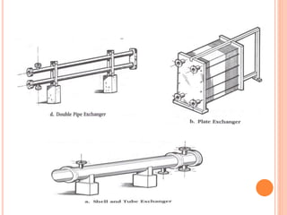
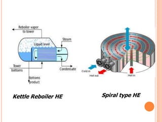
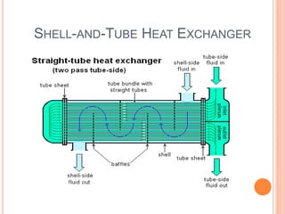
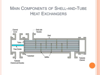
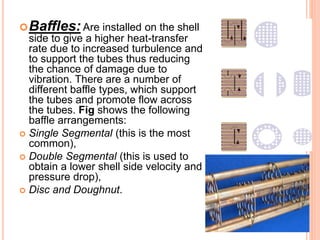
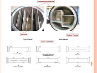
HEATEXCHANGER
 Patel Chintan 09
 Ginoya Jay 10
 Mayani Chirag 12
WHAT IS EXCHANGER
 It is a heat exchange equipment that allows
exchange of heat between hot and cold process
streams.
Example:
a) Intercooler and preheaters.
b) Condensers and boilers.
c) Regenerators.
d) Automobile radiators etc.
•Heat exchangers are one of the most common
pieces of equipment found in all plants.
•Heat Exchangers are components that allow the
transfer of heat from one fluid (liquid or gas) to
another fluid.
•In a heat exchanger there is no direct contact
between the two fluids. The heat is transferred
from the hot fluid to the metal isolating the two
fluids and then to the cooler fluid.
TYPES
 According to nature of heat exchange process.
1. Direct contact heat exchanger: e.g. Cooling tower, jet
condenser, etc.
2. Indirect contact heat exchanger: e.g. Regenerators,
Surface exchangers, etc.
 According to relative direction of fluid motion.
1. Parallel flow
2. Counter flow
3. Cross flow
ACC. TO DESIGN AND CONSTRUCTIONAL FEATURE
 Double pipe heat exchanger.
 Shell and tubes heat exchanger.
 Plate type heat exchanger.
 Spiral heat exchanger.
 Kettle reboiler heat exchanger.
 U -Tube heat exchanger
Kettle Reboiler HE Spiral type HE
DOUBLE PIPE
 It is the simplest type of heat exchanger used in
industry
 These heat exchangers are cheap for both
design and maintenance, making them a good
choice for small industries.
 In this exchanger, one of the fluid flows through
the inside pipe and another fluid flow flows
through the annular space created between tow
concentric pipes either in parallel or counter-
current fashion.
Parallel flow Counter-current flow
 This is usually employed for decreasing the
temperature of a hot fluid with help of a cold fluid
when flow rates are low.
 These are commonly used in refrigeration
services.
 These exchanger are usually assembled in
effective lengths of 3.65m,4.57m,6m.
 The distance in each leg over which the heat
transfer occurs is termed as the effective length.
ADVANTAGES
 Very simple to construct·
 Very easy of operation.
 Apart from this, the double pipe heat
exchanger is very attractive where the total
heat transfer surface required is small.
 This is simple in construction, cheap and
easy to clean.
DISADVANTAGES
 Small heat transfer surface in large floor
space as compared to other type(e.g. shell
and tube type heat exchanger).
 Dismantling etc, require large time.
 Maximum leakage points.
INDUSTRIAL APPLICATION
 Pasteurization
 Digester heating
 Heat recovery
 Pre-heating
 Effluent cooling.
SHELL-AND-TUBE HEAT EXCHANGER
 Shell-and-Tube Heat Exchangers are the most
important type of HE.
 It is used in almost every type of industry.
 For variety of industrial services where large heat
transfer surface are require, shell and tube heat
exchanger is used.
 This type of heat exchanger consists of a set of tubes
in a container called a shell.
 The fluid flowing inside the tubes is called the tube
side fluid and the fluid flowing on the outside of the
tubes is the shell side fluid.
 A shell and tube heat exchanger consists of a
number of parallel tubes, ends of which are
mounted in the tube sheet and the entire tube
bundle is enclosed in a close fitting cylindrical shell.
 In this exchanger, one fluid flows through the tubes
and is called as the tube side fluid; while the other
fluid flows through the outside of the tube is called
as the shell side fluid.
 Two fluids are in thermal contact but are physically
separated by a metal wall of the tubes.
MAIN COMPONENTS OF SHELL-AND-TUBE
HEAT EXCHANGERS
HEAT-EXCHANGER TERMS
 shell: It is usually cylindrical through which
one of the fluid flows in one or more passes,
commonly made of carbon shell. It may be
cut to the required length from a standard
pipe up to 60cm dia. having thickness of
shell made of carbon steel varies from 5mm
to 11mm depending upon the diameter.
 Tubes: Tubes may be of various lengths and
sizes. The outside diameter of tubes vary
from 6mm to 40mm and 19mm to 25mm
are common.
 Tie rods: Tie rods and spacers are used
for two reasons: 1) hold the baffle assembly
together; and 2) maintain the selected baffle
spacing. Tie rod are fixed at one end in the
sheet by making blind holes. Usually, 4 to 6 tie
rods with atleast 10mm diameter are
necessary
 Tube sheet: It is essentially a flat circular with
a provision for making gasketed joint, around
the periphery. A large number of holes are
drilled in the tube sheet according to the pitch
requirements, thickness ranges from 6mm to
25.4mm for tube outside dia. of 6mm to
40mm.
 Tube pitch: The shortest centre
to centre distance between the
adjacent tubes is called as tube
pitch.
 Clearance: The shortest distance
between two tubes is called the
clearance.
 The square layouts are
required where it is necessary
to get at the tube surface for
mechanical cleaning. The
triangular arrangement allows
more tubes in a given space.
Baffles: Are installed on the shell
side to give a higher heat-transfer
rate due to increased turbulence and
to support the tubes thus reducing
the chance of damage due to
vibration. There are a number of
different baffle types, which support
the tubes and promote flow across
the tubes. Fig shows the following
baffle arrangements:
 Single Segmental (this is the most
common),
 Double Segmental (this is used to
obtain a lower shell side velocity and
pressure drop),
 Disc and Doughnut.
 Shell side and Tube side passes: with the help of passes, we
can change the direction of flow in the shell and tubes. Passes
are generally used to obtain higher velocities and longer paths for
a fluid to travel, without increasing the length of a exchanger, that
leads to high heat transfer rates.
The passes on shell side are : single pass, two pass,
single split pass. The passes on the tube side are: one, two, four,
six up to twelve. passes on the tube side are formed by partitions
placed in the shell cover and channels.
When we use a single pass partition on the tube side,
a tube side fluid flows twice through a heat exchanger. In this
case, the pass partition divides the tubes equally in two sections.
Multipass construction decreases the cross section of
the fluid path that increases the fluid velocity which in turn
increases the heat transfer coefficient.
ADVANTAGES
 Less costly than removable bundle heat
exchangers.
 Provides maximum heat transfer surface per given
shell and tube size.
 Provides multi-tube-pass arrangements.
 High surface per given shell and tube size.
 Capable of withstanding thermal shock
DISADVANTAGES
 Shell side can be cleaned only by chemical
means.
 Shell side fluids limited to nonvolatile
and/or non-toxic fluids. i.e. lube oils. hydraulic
oils.
 Tube side arrangements limited to one or two
passes.
 Tubes expand as a group. not individually.
INDUSTRIAL APPLICATION
 Oil transformer cooling
 Exhaust gas heat recovery
 Waste heat recovery
 Steam heating
 Solvent / Distillate process.etc
REFERENCE
 http://www.steelcraft.ca/fcf/index.php
 info@cmsheattransfer.com
 http://www.thermopedia.com/content/1121.
.
THANK YOU

heat exchanger

  • 1.
    HEATEXCHANGER  Patel Chintan09  Ginoya Jay 10  Mayani Chirag 12
  • 2.
    WHAT IS EXCHANGER It is a heat exchange equipment that allows exchange of heat between hot and cold process streams. Example: a) Intercooler and preheaters. b) Condensers and boilers. c) Regenerators. d) Automobile radiators etc.
  • 3.
    •Heat exchangers areone of the most common pieces of equipment found in all plants. •Heat Exchangers are components that allow the transfer of heat from one fluid (liquid or gas) to another fluid. •In a heat exchanger there is no direct contact between the two fluids. The heat is transferred from the hot fluid to the metal isolating the two fluids and then to the cooler fluid.
  • 4.
    TYPES  According tonature of heat exchange process. 1. Direct contact heat exchanger: e.g. Cooling tower, jet condenser, etc. 2. Indirect contact heat exchanger: e.g. Regenerators, Surface exchangers, etc.  According to relative direction of fluid motion. 1. Parallel flow 2. Counter flow 3. Cross flow
  • 5.
    ACC. TO DESIGNAND CONSTRUCTIONAL FEATURE  Double pipe heat exchanger.  Shell and tubes heat exchanger.  Plate type heat exchanger.  Spiral heat exchanger.  Kettle reboiler heat exchanger.  U -Tube heat exchanger
  • 7.
    Kettle Reboiler HESpiral type HE
  • 8.
    DOUBLE PIPE  Itis the simplest type of heat exchanger used in industry  These heat exchangers are cheap for both design and maintenance, making them a good choice for small industries.  In this exchanger, one of the fluid flows through the inside pipe and another fluid flow flows through the annular space created between tow concentric pipes either in parallel or counter- current fashion.
  • 9.
  • 10.
     This isusually employed for decreasing the temperature of a hot fluid with help of a cold fluid when flow rates are low.  These are commonly used in refrigeration services.  These exchanger are usually assembled in effective lengths of 3.65m,4.57m,6m.  The distance in each leg over which the heat transfer occurs is termed as the effective length.
  • 11.
    ADVANTAGES  Very simpleto construct·  Very easy of operation.  Apart from this, the double pipe heat exchanger is very attractive where the total heat transfer surface required is small.  This is simple in construction, cheap and easy to clean.
  • 12.
    DISADVANTAGES  Small heattransfer surface in large floor space as compared to other type(e.g. shell and tube type heat exchanger).  Dismantling etc, require large time.  Maximum leakage points.
  • 13.
    INDUSTRIAL APPLICATION  Pasteurization Digester heating  Heat recovery  Pre-heating  Effluent cooling.
  • 14.
  • 15.
     Shell-and-Tube HeatExchangers are the most important type of HE.  It is used in almost every type of industry.  For variety of industrial services where large heat transfer surface are require, shell and tube heat exchanger is used.  This type of heat exchanger consists of a set of tubes in a container called a shell.  The fluid flowing inside the tubes is called the tube side fluid and the fluid flowing on the outside of the tubes is the shell side fluid.
  • 16.
     A shelland tube heat exchanger consists of a number of parallel tubes, ends of which are mounted in the tube sheet and the entire tube bundle is enclosed in a close fitting cylindrical shell.  In this exchanger, one fluid flows through the tubes and is called as the tube side fluid; while the other fluid flows through the outside of the tube is called as the shell side fluid.  Two fluids are in thermal contact but are physically separated by a metal wall of the tubes.
  • 17.
    MAIN COMPONENTS OFSHELL-AND-TUBE HEAT EXCHANGERS
  • 18.
    HEAT-EXCHANGER TERMS  shell:It is usually cylindrical through which one of the fluid flows in one or more passes, commonly made of carbon shell. It may be cut to the required length from a standard pipe up to 60cm dia. having thickness of shell made of carbon steel varies from 5mm to 11mm depending upon the diameter.  Tubes: Tubes may be of various lengths and sizes. The outside diameter of tubes vary from 6mm to 40mm and 19mm to 25mm are common.
  • 20.
     Tie rods:Tie rods and spacers are used for two reasons: 1) hold the baffle assembly together; and 2) maintain the selected baffle spacing. Tie rod are fixed at one end in the sheet by making blind holes. Usually, 4 to 6 tie rods with atleast 10mm diameter are necessary  Tube sheet: It is essentially a flat circular with a provision for making gasketed joint, around the periphery. A large number of holes are drilled in the tube sheet according to the pitch requirements, thickness ranges from 6mm to 25.4mm for tube outside dia. of 6mm to 40mm.
  • 21.
     Tube pitch:The shortest centre to centre distance between the adjacent tubes is called as tube pitch.  Clearance: The shortest distance between two tubes is called the clearance.  The square layouts are required where it is necessary to get at the tube surface for mechanical cleaning. The triangular arrangement allows more tubes in a given space.
  • 22.
    Baffles: Are installedon the shell side to give a higher heat-transfer rate due to increased turbulence and to support the tubes thus reducing the chance of damage due to vibration. There are a number of different baffle types, which support the tubes and promote flow across the tubes. Fig shows the following baffle arrangements:  Single Segmental (this is the most common),  Double Segmental (this is used to obtain a lower shell side velocity and pressure drop),  Disc and Doughnut.
  • 23.
     Shell sideand Tube side passes: with the help of passes, we can change the direction of flow in the shell and tubes. Passes are generally used to obtain higher velocities and longer paths for a fluid to travel, without increasing the length of a exchanger, that leads to high heat transfer rates. The passes on shell side are : single pass, two pass, single split pass. The passes on the tube side are: one, two, four, six up to twelve. passes on the tube side are formed by partitions placed in the shell cover and channels. When we use a single pass partition on the tube side, a tube side fluid flows twice through a heat exchanger. In this case, the pass partition divides the tubes equally in two sections. Multipass construction decreases the cross section of the fluid path that increases the fluid velocity which in turn increases the heat transfer coefficient.
  • 25.
    ADVANTAGES  Less costlythan removable bundle heat exchangers.  Provides maximum heat transfer surface per given shell and tube size.  Provides multi-tube-pass arrangements.  High surface per given shell and tube size.  Capable of withstanding thermal shock
  • 26.
    DISADVANTAGES  Shell sidecan be cleaned only by chemical means.  Shell side fluids limited to nonvolatile and/or non-toxic fluids. i.e. lube oils. hydraulic oils.  Tube side arrangements limited to one or two passes.  Tubes expand as a group. not individually.
  • 27.
    INDUSTRIAL APPLICATION  Oiltransformer cooling  Exhaust gas heat recovery  Waste heat recovery  Steam heating  Solvent / Distillate process.etc
  • 28.
  • 29.