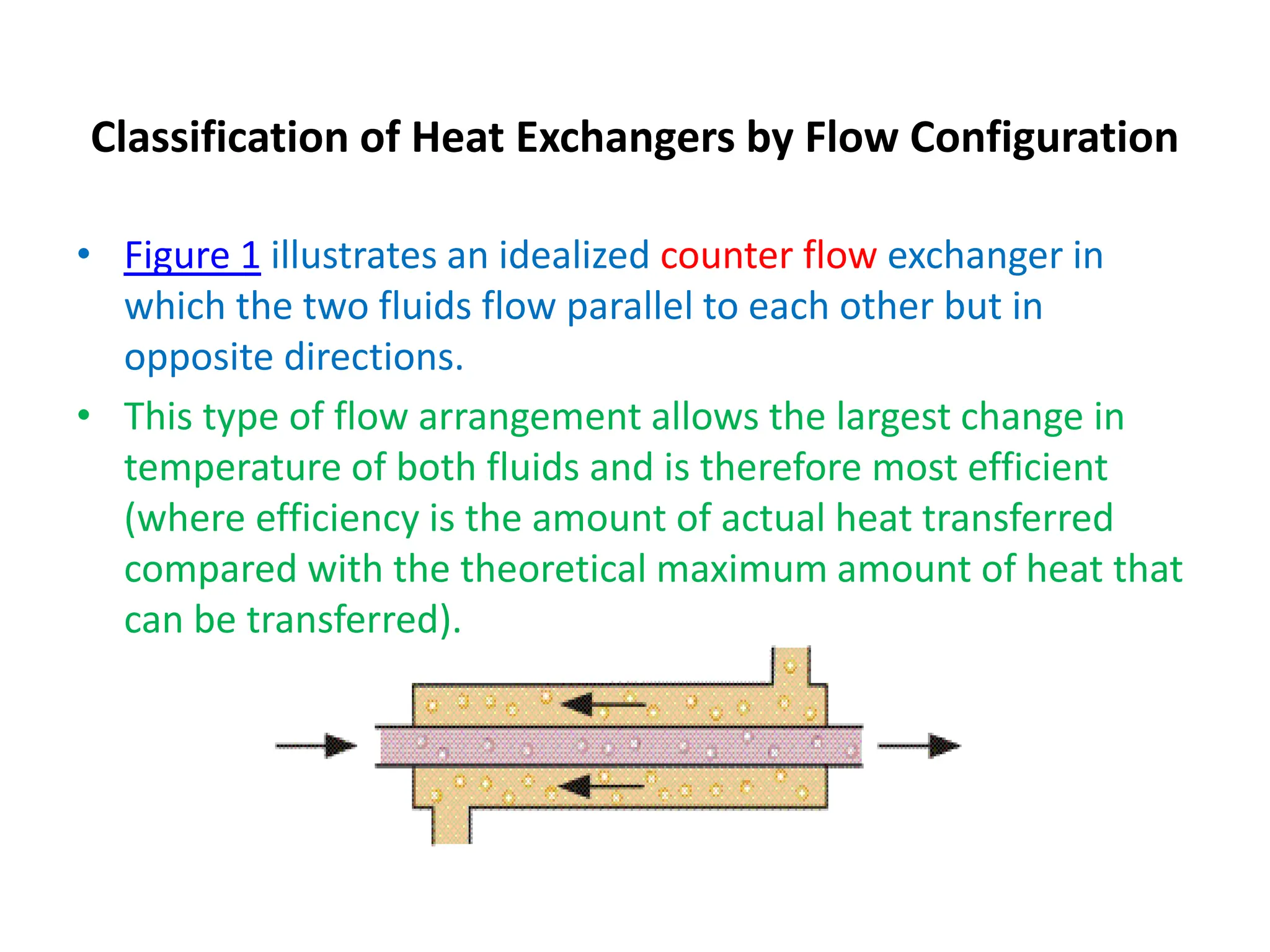
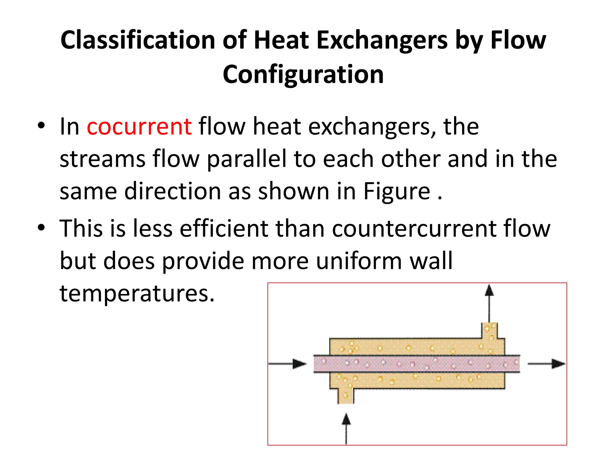
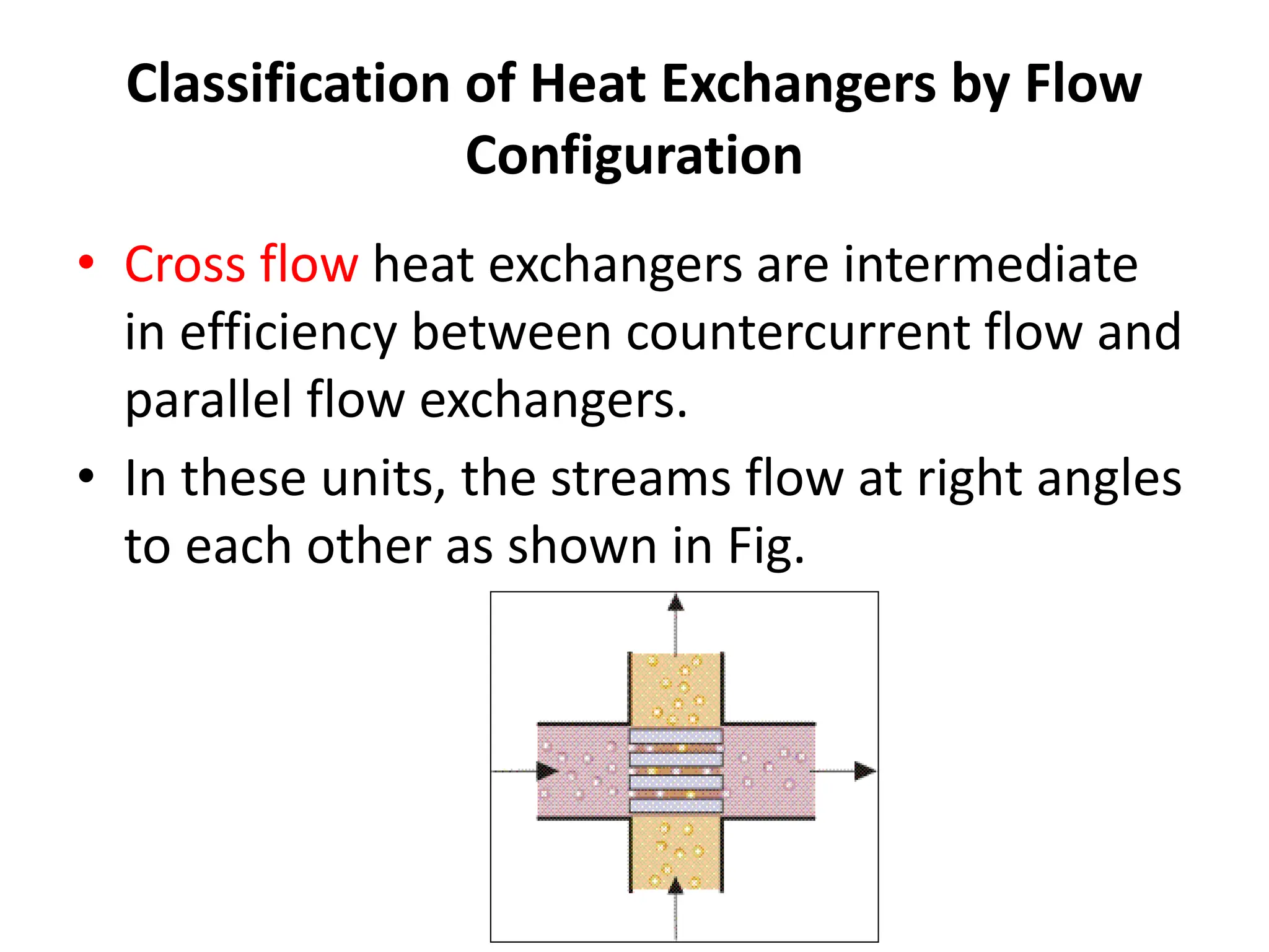
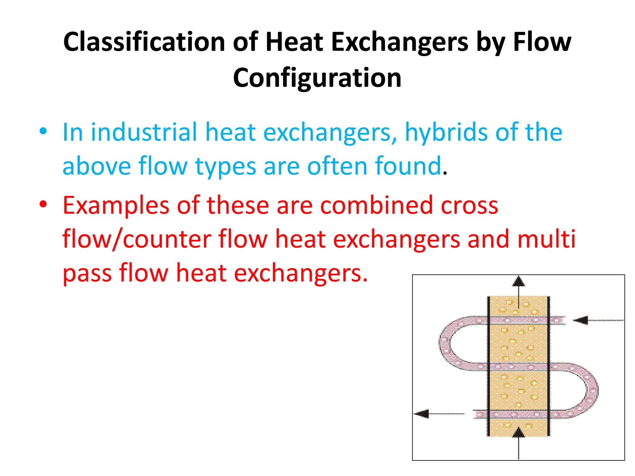
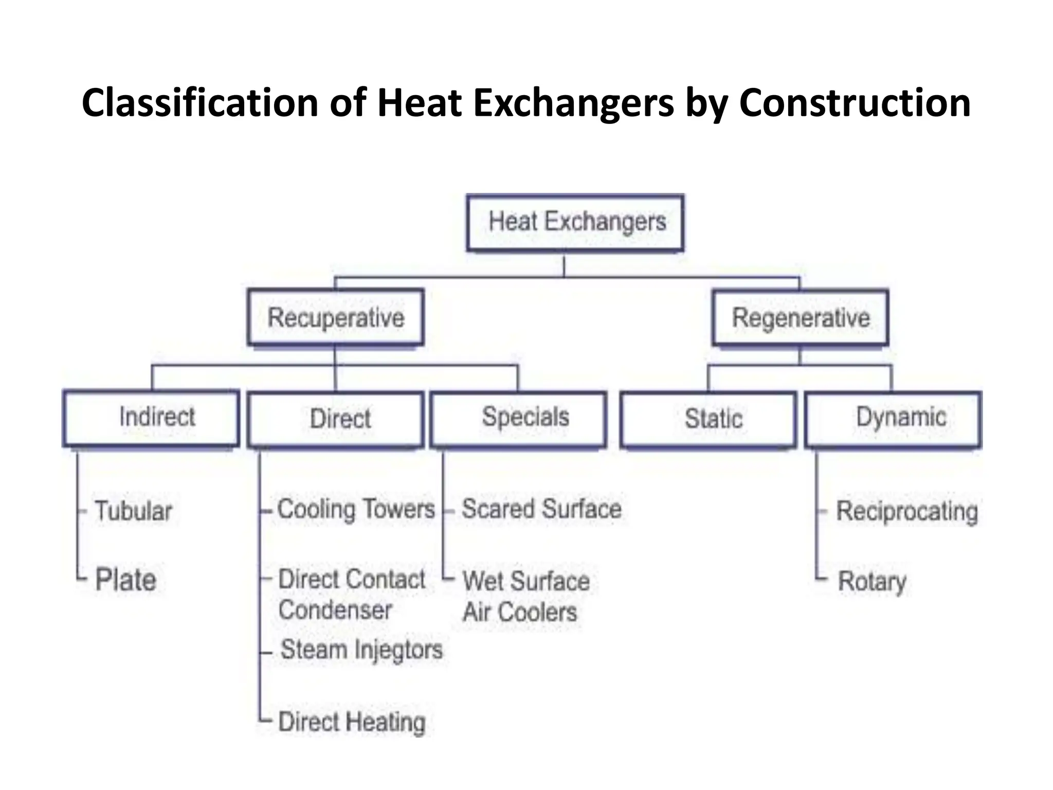
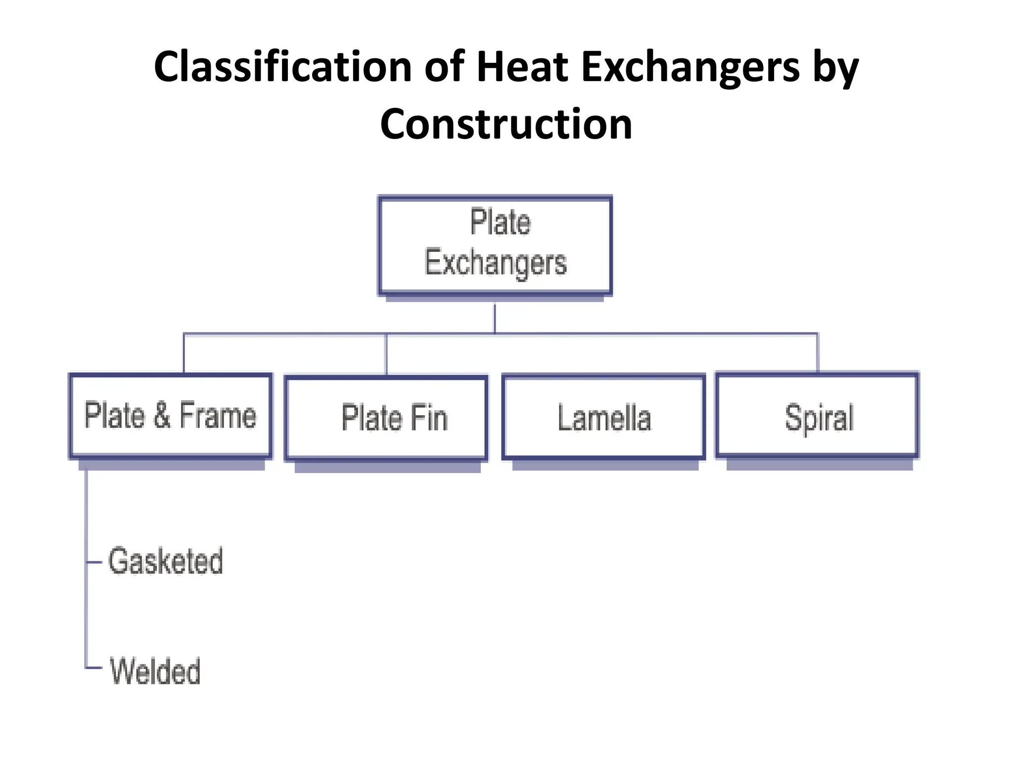
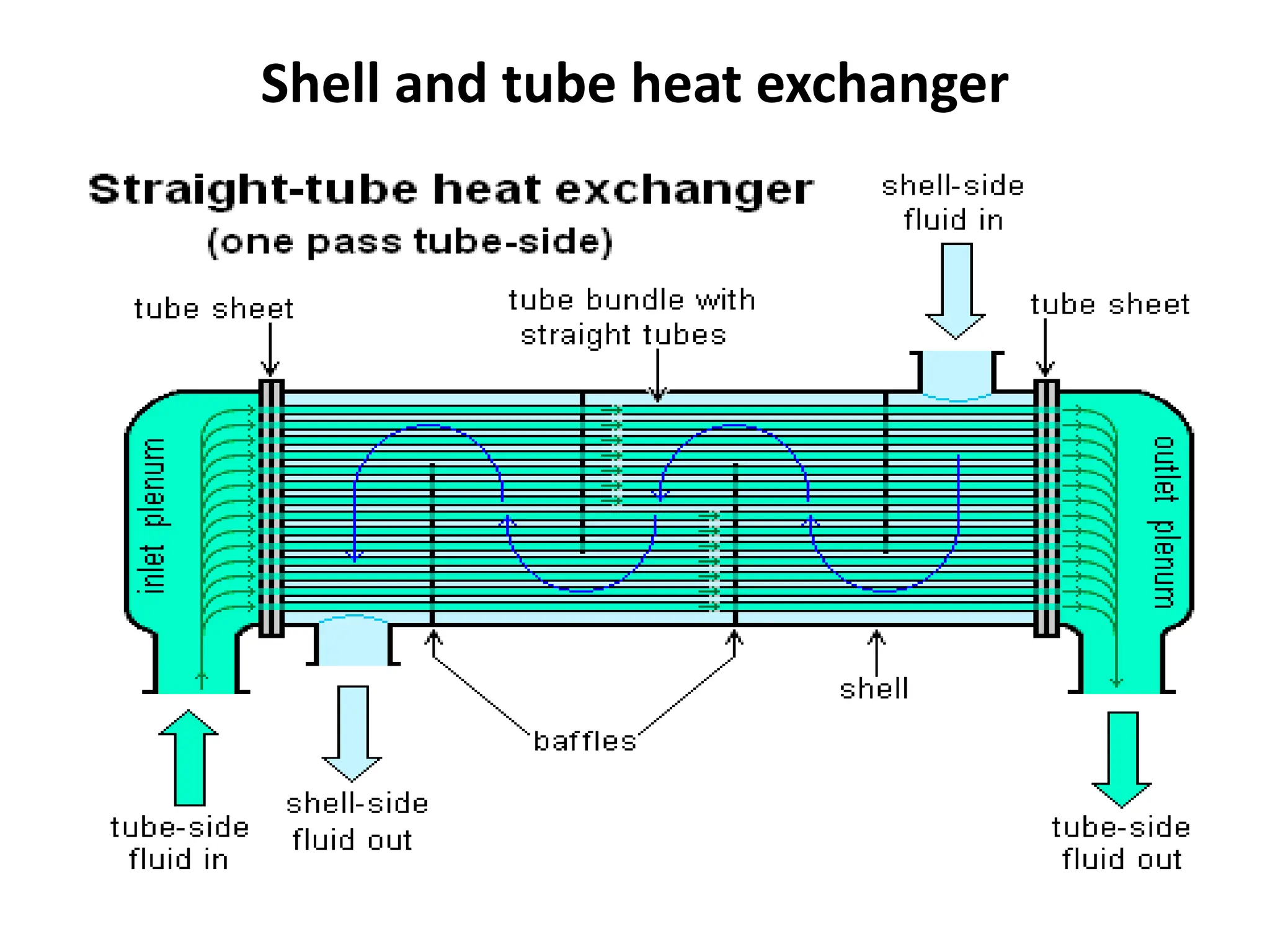
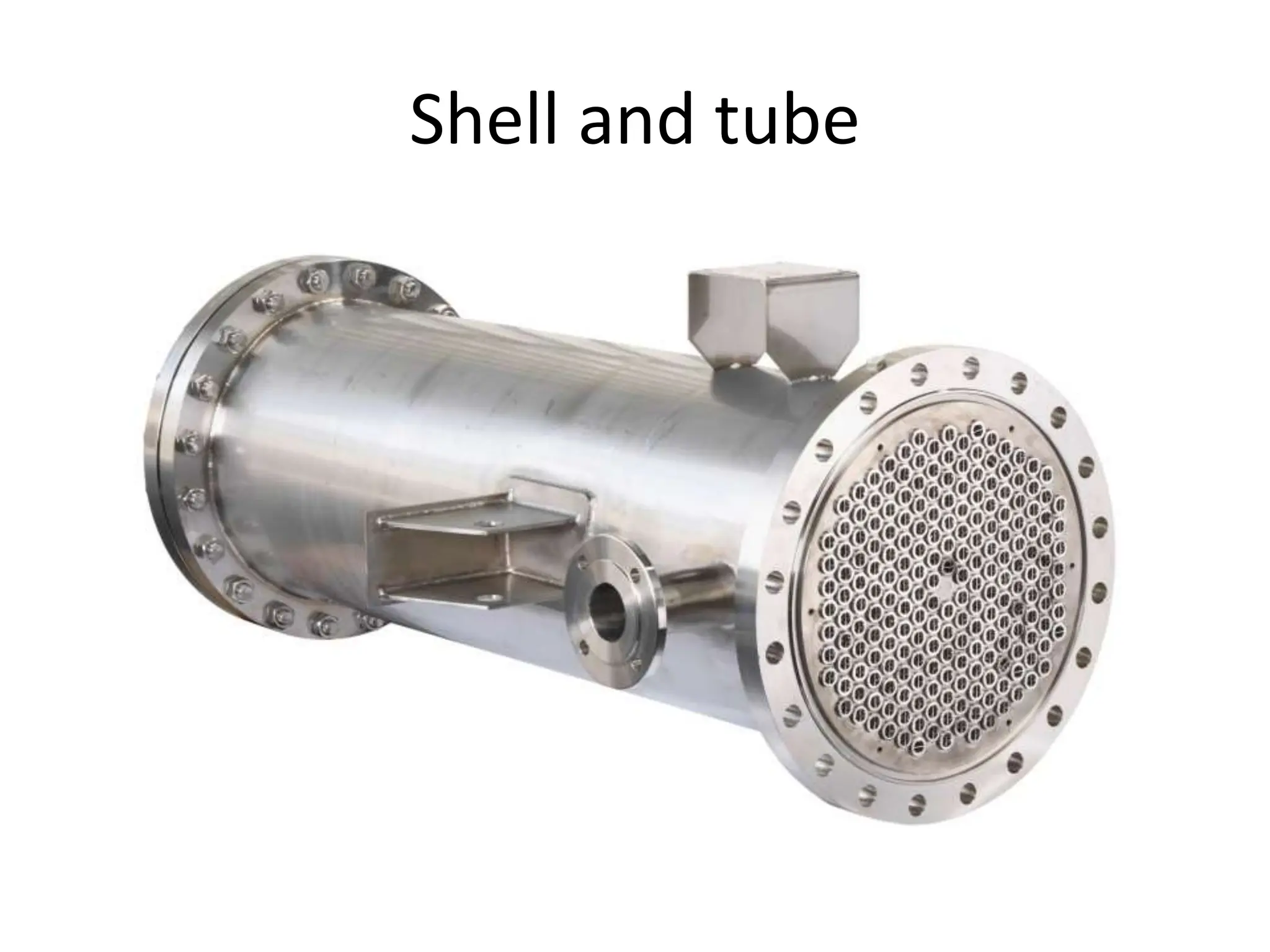
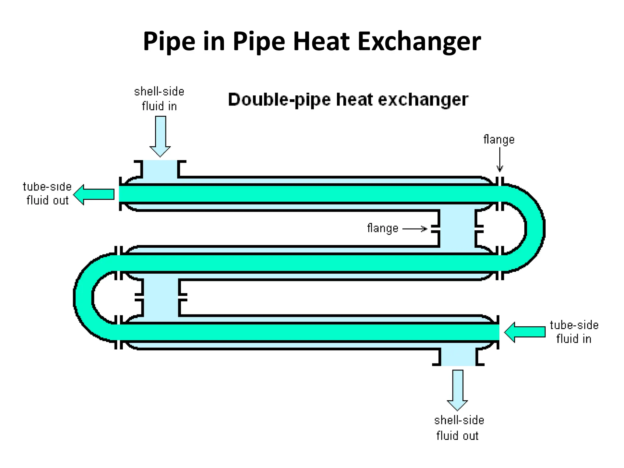
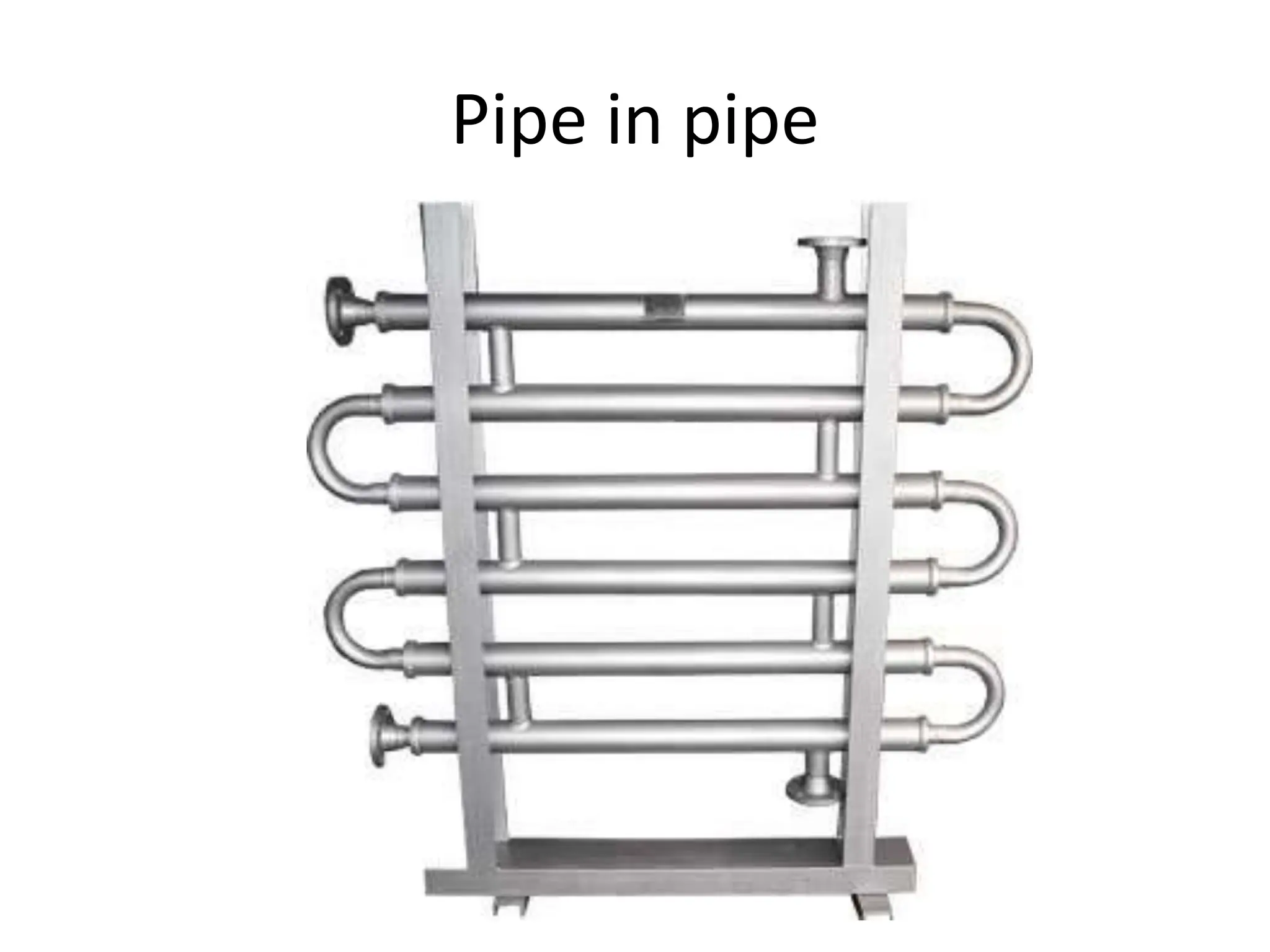
Heat exchanger
•A heat exchanger is a piece of equipment built for efficient heat
transfer from one medium to another.
•The media may be separated by a solid wall to prevent mixing or
they may be in direct contact.
•They are widely used in space heating, refrigeration, air
conditioning, power plants, chemical plants, petrochemical plants,
petroleum refineries, natural gas processing, and sewage
treatment.
•The classic example of a heat exchanger is found in an internal
combustion engine in which a circulating fluid known as engine
coolant flows through radiator coils and air flows past the coils,
which cools the coolant and heats the incoming air.
classification
• Classification of Heat Exchangers by Flow
Configuration
• There are four basic flow configurations:
• Counter Flow
• Cocurrent Flow
• Crossflow
• Hybrids such as Cross Counterflow and Multi
Pass Flow
Classification of Heat Exchangers by Flow Configuration
• Figure 1 illustrates an idealized counter flow exchanger in
which the two fluids flow parallel to each other but in
opposite directions.
• This type of flow arrangement allows the largest change in
temperature of both fluids and is therefore most efficient
(where efficiency is the amount of actual heat transferred
compared with the theoretical maximum amount of heat that
can be transferred).
Classification of Heat Exchangers by Flow
Configuration
• In cocurrent flow heat exchangers, the
streams flow parallel to each other and in the
same direction as shown in Figure .
• This is less efficient than countercurrent flow
but does provide more uniform wall
temperatures.
Classification of Heat Exchangers by Flow
Configuration
• Cross flow heat exchangers are intermediate
in efficiency between countercurrent flow and
parallel flow exchangers.
• In these units, the streams flow at right angles
to each other as shown in Fig.
Classification of Heat Exchangers by Flow
Configuration
• In industrial heat exchangers, hybrids of the
above flow types are often found.
• Examples of these are combined cross
flow/counter flow heat exchangers and multi
pass flow heat exchangers.
Classification of Heat Exchangers by Construction
Classification of Heat Exchangers by
Construction
Classification of Heat Exchangers by
Construction
Classification of Heat Exchangers by
Construction
• A Recuperative Heat Exchanger has separate flow paths for
each fluid and fluids flow simultaneously through the
exchanger exchanging heat across the wall separating the
flow paths.
• A Regenerative Heat Exchanger has a single flow path,
which the hot and cold fluids alternately pass through.
• In a regenerative heat exchanger, the flow path normally
consists of a matrix, which is heated when the hot fluid
passes through it (this is known as the "hot blow"). This
heat is then released to the cold fluid when this flows
through the matrix (the "cold blow").
Shell and tube heat exchanger
1) Shell and tube heat exchangers consist of a series of tubes.
2) One set of these tubes contains the fluid that must be
either heated or cooled.
3) The second fluid runs over the tubes that are being heated
or cooled so that it can either provide the heat or absorb
the heat required.
4) A set of tubes is called the tube bundle and can be made up
of several types of tubes: plain, longitudinally finned, etc.
5) Shell and tube heat exchangers are typically used for high-
pressure applications (with pressures greater than 30 bar
and temperatures greater than 260 °C).
6) This is because the shell and tube heat exchangers are
robust due to their shape.
Shell and tube heat exchanger
Applications and uses
• The simple design of a shell and tube heat exchanger makes it
an ideal cooling solution for a wide variety of applications.
• One of the most common applications is the cooling of
hydraulic fluid and oil in engines, transmissions and hydraulic
power packs.
• With the right choice of materials they can also be used to
cool or heat other mediums, such as swimming pool water or
charge air.
• One of the big advantages of using a shell and tube heat
exchanger is that they are often easy to service, particularly
with models where a floating tube bundle (where the tube
plates are not welded to the outer shell) is available.
Shell and tube
Shell and Coil Heat Exchangers
Shell and coil
Shell and Coil Heat Exchangers
• The shell and coil heat exchangers are constructed using
circular layers of helically corrugated tubes placed inside a
light compact shell.
• The fluid in each layer flows in the opposite direction to the
layer surrounding it, producing a criss-cross pattern.
• The large number of closely packed tubes creates a significant
heat transfer surface within a light compact shell.
• The alternate layers create a swift uniform heating of fluids
increasing the total heat transfer coefficient.
• The corrugated tubes produce a turbulent flow where the
desired feature of fluctuating velocities is achieved.
Advantages of the shell and coil heat
exchangers:
•
The shell and coil design is the perfect choice whenever high heat
transfer rates, compact design and low maintenance costs are high
priorities. Other benefits include:
• High Performance: the unique coil arrangement has a large heat
transfer area meaning high heat transfer coefficients.
• Compact and Lightweight: closely packed tubes makes our shell and coil
exchangers compact and lightweight. Small footprint makes it easy to
install where space is limited and hard to access.
• Low Maintenance Costs: corrugated tube design produces a high
turbulent flow, which reduces deposit build-up and fouling. This means
longer operating cycles between scheduled cleaning intervals.
• Low Installation Costs: vertical installation makes it ideal for hydronic
heating and cooling systems where space is an issue.
Advantages of the shell and coil heat
exchangers:
• Higher Temperature Differentials: helical design allows for
higher temperatures and extreme temperature differentials
without high stress levels and costly expansion joints.
• Flexible Designs: variety of model types and configurations
allow shell and coil heat exchangers to be used with a wide
range of pressures, temperatures, and flows.
• Low Pressure Drop:
• Easy selection based on sub-station space requirements
and heat or cooling load.
Shell and Coil Heat Exchangers
• Shell and Coil Applications:
The shell and coil design were designed specifically for the
hydronic markets including:
• Heating Systems:
• Chilled Water Systems:
• Ground Water Systems:
• Residential Use:
• District Heating Systems: heating systems that distribute heat
from one or more heating sources to multiple buildings.
• Shell & Coil Heat Exchangers are designed for steam-water,
water-water and glycol applications
Pipe in Pipe Heat Exchanger
• A Double Pipe Heat Exchanger is one of the simplest forms of
Shell and Tubular Heat Exchanger.
• Here, just one pipe inside another larger pipe. To make a Unit
very Compact, The Arrangement is made Multiple Times and
Continues Serial and Parallel flow.
• One fluid flows through the surrounded by pipe and the other
flows through the annulus between the two pipes.
• The wall of the inner pipe is the heat transfer surface. This is
also called as a hairpin Heat Exchanger.
• These are might have only one inside pipe, or it may have
multiple inside tubes, but it will forever have the doubling back
feature shown.
• In some of the Special Cases the Fins also Used in Tube side
Advantages
• A primary advantage of a hairpin or double pipe heat
exchanger is to facilitate it can be operated in a true counter
flow pattern, which is the a large amount efficient flow
pattern.
• That is, it will give the highest overall heat transfer coefficient
for the double pipe heat exchanger design.
• Also, hairpin and double pipe heat exchangers can handle
high pressures and temperatures well. When they are
operating in true counter flow, they can operate among a
temperature cross, that is, where the cold side outlet
temperature is higher than the hot side outlet temperature.
• The primary advantage of a concentric configuration, as
opposed to a plate or shell and tube heat exchanger, is the
Advantages
• As such, the insides of both surfaces are easy
to clean and maintain, making it ideal for
fluids that cause fouling.
Disadvantages
• There are significant disadvantages however,
the two most noticeable being their high cost
in proportion to heat transfer area;
• and the impractical lengths required for high
heat duties.
• They also suffer from comparatively high heat
losses via their large, outer shells.
Pipe in pipe
Plate type heat exchanger
• A plate heat exchanger consists
of a series of thin corrugated
metal plates between which a
number of channels are formed,
with the primary and secondary
fluids flowing through alternate
channels.
• Heat transfer takes place from
the primary fluid steam to the
secondary process fluid in
adjacent channels across the
plate. Figure 2.13.3 shows a
schematic representation of a
plate heat exchanger.
Plate Heat Exchanger
• The plate heat exchanger consists of a specific number of plates arranged
between the pressure & the fixed frame.
• The plates are having corrugations with different designs which increase
the total surface area for the heat exchange.
• The plates are movable within the frame and rest on the carrying bar on
the top and the bottom of the frame.
• The plates are arranged in pairs which are opposite of each other forming
a honey comb pattern when viewed sideways.
• The plate corrugations promote fluid turbulence and increase the heat
transfer.
• The fixed and the pressure plate are supported by the supporting column.
• The plates are fitted with each other with gaskets which seal the material
from coming out sideways as well as through the holes on the plates. The
alternate arrangement of the gaskets prevents the mixing of the fluids
within the channels.
Plate type heat exchanger
• The steam heat exchanger market was
dominated in the past by the shell and tube
heat exchanger, whilst plate heat exchangers
have often been favoured in the food
processing industry and used water heating.
• However, recent design advances mean that
plate heat exchangers are now equally suited to
steam heating applications.
Plate type heat exchanger
• Advantages of Plate Type Heat Exchanger
• Low cost of operation
• Low cost of maintenance
• Easy to clean
• Highly efficient heat transfer
• Future changes are possible by fitting extra heat transfer plates
• Less floor space required
• Applications of Plate type Heat Exchanger
• Power generation applications
• In food, Dairy and brewing industries
• Refrigerants in cooling systems

Heat Exchangers, Its types and classifications. functioning of each type

  • 1.
    Heat exchanger •A heatexchanger is a piece of equipment built for efficient heat transfer from one medium to another. •The media may be separated by a solid wall to prevent mixing or they may be in direct contact. •They are widely used in space heating, refrigeration, air conditioning, power plants, chemical plants, petrochemical plants, petroleum refineries, natural gas processing, and sewage treatment. •The classic example of a heat exchanger is found in an internal combustion engine in which a circulating fluid known as engine coolant flows through radiator coils and air flows past the coils, which cools the coolant and heats the incoming air.
  • 2.
    classification • Classification ofHeat Exchangers by Flow Configuration • There are four basic flow configurations: • Counter Flow • Cocurrent Flow • Crossflow • Hybrids such as Cross Counterflow and Multi Pass Flow
  • 3.
    Classification of HeatExchangers by Flow Configuration • Figure 1 illustrates an idealized counter flow exchanger in which the two fluids flow parallel to each other but in opposite directions. • This type of flow arrangement allows the largest change in temperature of both fluids and is therefore most efficient (where efficiency is the amount of actual heat transferred compared with the theoretical maximum amount of heat that can be transferred).
  • 4.
    Classification of HeatExchangers by Flow Configuration • In cocurrent flow heat exchangers, the streams flow parallel to each other and in the same direction as shown in Figure . • This is less efficient than countercurrent flow but does provide more uniform wall temperatures.
  • 5.
    Classification of HeatExchangers by Flow Configuration • Cross flow heat exchangers are intermediate in efficiency between countercurrent flow and parallel flow exchangers. • In these units, the streams flow at right angles to each other as shown in Fig.
  • 6.
    Classification of HeatExchangers by Flow Configuration • In industrial heat exchangers, hybrids of the above flow types are often found. • Examples of these are combined cross flow/counter flow heat exchangers and multi pass flow heat exchangers.
  • 7.
    Classification of HeatExchangers by Construction
  • 8.
    Classification of HeatExchangers by Construction
  • 9.
    Classification of HeatExchangers by Construction
  • 10.
    Classification of HeatExchangers by Construction • A Recuperative Heat Exchanger has separate flow paths for each fluid and fluids flow simultaneously through the exchanger exchanging heat across the wall separating the flow paths. • A Regenerative Heat Exchanger has a single flow path, which the hot and cold fluids alternately pass through. • In a regenerative heat exchanger, the flow path normally consists of a matrix, which is heated when the hot fluid passes through it (this is known as the "hot blow"). This heat is then released to the cold fluid when this flows through the matrix (the "cold blow").
  • 11.
    Shell and tubeheat exchanger 1) Shell and tube heat exchangers consist of a series of tubes. 2) One set of these tubes contains the fluid that must be either heated or cooled. 3) The second fluid runs over the tubes that are being heated or cooled so that it can either provide the heat or absorb the heat required. 4) A set of tubes is called the tube bundle and can be made up of several types of tubes: plain, longitudinally finned, etc. 5) Shell and tube heat exchangers are typically used for high- pressure applications (with pressures greater than 30 bar and temperatures greater than 260 °C). 6) This is because the shell and tube heat exchangers are robust due to their shape.
  • 12.
    Shell and tubeheat exchanger
  • 13.
    Applications and uses •The simple design of a shell and tube heat exchanger makes it an ideal cooling solution for a wide variety of applications. • One of the most common applications is the cooling of hydraulic fluid and oil in engines, transmissions and hydraulic power packs. • With the right choice of materials they can also be used to cool or heat other mediums, such as swimming pool water or charge air. • One of the big advantages of using a shell and tube heat exchanger is that they are often easy to service, particularly with models where a floating tube bundle (where the tube plates are not welded to the outer shell) is available.
  • 14.
  • 15.
    Shell and CoilHeat Exchangers
  • 16.
  • 17.
    Shell and CoilHeat Exchangers • The shell and coil heat exchangers are constructed using circular layers of helically corrugated tubes placed inside a light compact shell. • The fluid in each layer flows in the opposite direction to the layer surrounding it, producing a criss-cross pattern. • The large number of closely packed tubes creates a significant heat transfer surface within a light compact shell. • The alternate layers create a swift uniform heating of fluids increasing the total heat transfer coefficient. • The corrugated tubes produce a turbulent flow where the desired feature of fluctuating velocities is achieved.
  • 18.
    Advantages of theshell and coil heat exchangers: • The shell and coil design is the perfect choice whenever high heat transfer rates, compact design and low maintenance costs are high priorities. Other benefits include: • High Performance: the unique coil arrangement has a large heat transfer area meaning high heat transfer coefficients. • Compact and Lightweight: closely packed tubes makes our shell and coil exchangers compact and lightweight. Small footprint makes it easy to install where space is limited and hard to access. • Low Maintenance Costs: corrugated tube design produces a high turbulent flow, which reduces deposit build-up and fouling. This means longer operating cycles between scheduled cleaning intervals. • Low Installation Costs: vertical installation makes it ideal for hydronic heating and cooling systems where space is an issue.
  • 19.
    Advantages of theshell and coil heat exchangers: • Higher Temperature Differentials: helical design allows for higher temperatures and extreme temperature differentials without high stress levels and costly expansion joints. • Flexible Designs: variety of model types and configurations allow shell and coil heat exchangers to be used with a wide range of pressures, temperatures, and flows. • Low Pressure Drop: • Easy selection based on sub-station space requirements and heat or cooling load.
  • 20.
    Shell and CoilHeat Exchangers • Shell and Coil Applications: The shell and coil design were designed specifically for the hydronic markets including: • Heating Systems: • Chilled Water Systems: • Ground Water Systems: • Residential Use: • District Heating Systems: heating systems that distribute heat from one or more heating sources to multiple buildings. • Shell & Coil Heat Exchangers are designed for steam-water, water-water and glycol applications
  • 21.
    Pipe in PipeHeat Exchanger
  • 22.
    Pipe in PipeHeat Exchanger • A Double Pipe Heat Exchanger is one of the simplest forms of Shell and Tubular Heat Exchanger. • Here, just one pipe inside another larger pipe. To make a Unit very Compact, The Arrangement is made Multiple Times and Continues Serial and Parallel flow. • One fluid flows through the surrounded by pipe and the other flows through the annulus between the two pipes. • The wall of the inner pipe is the heat transfer surface. This is also called as a hairpin Heat Exchanger. • These are might have only one inside pipe, or it may have multiple inside tubes, but it will forever have the doubling back feature shown. • In some of the Special Cases the Fins also Used in Tube side
  • 23.
    Advantages • A primaryadvantage of a hairpin or double pipe heat exchanger is to facilitate it can be operated in a true counter flow pattern, which is the a large amount efficient flow pattern. • That is, it will give the highest overall heat transfer coefficient for the double pipe heat exchanger design. • Also, hairpin and double pipe heat exchangers can handle high pressures and temperatures well. When they are operating in true counter flow, they can operate among a temperature cross, that is, where the cold side outlet temperature is higher than the hot side outlet temperature. • The primary advantage of a concentric configuration, as opposed to a plate or shell and tube heat exchanger, is the
  • 24.
    Advantages • As such,the insides of both surfaces are easy to clean and maintain, making it ideal for fluids that cause fouling.
  • 25.
    Disadvantages • There aresignificant disadvantages however, the two most noticeable being their high cost in proportion to heat transfer area; • and the impractical lengths required for high heat duties. • They also suffer from comparatively high heat losses via their large, outer shells.
  • 26.
  • 27.
    Plate type heatexchanger • A plate heat exchanger consists of a series of thin corrugated metal plates between which a number of channels are formed, with the primary and secondary fluids flowing through alternate channels. • Heat transfer takes place from the primary fluid steam to the secondary process fluid in adjacent channels across the plate. Figure 2.13.3 shows a schematic representation of a plate heat exchanger.
  • 28.
    Plate Heat Exchanger •The plate heat exchanger consists of a specific number of plates arranged between the pressure & the fixed frame. • The plates are having corrugations with different designs which increase the total surface area for the heat exchange. • The plates are movable within the frame and rest on the carrying bar on the top and the bottom of the frame. • The plates are arranged in pairs which are opposite of each other forming a honey comb pattern when viewed sideways. • The plate corrugations promote fluid turbulence and increase the heat transfer. • The fixed and the pressure plate are supported by the supporting column. • The plates are fitted with each other with gaskets which seal the material from coming out sideways as well as through the holes on the plates. The alternate arrangement of the gaskets prevents the mixing of the fluids within the channels.
  • 29.
    Plate type heatexchanger • The steam heat exchanger market was dominated in the past by the shell and tube heat exchanger, whilst plate heat exchangers have often been favoured in the food processing industry and used water heating. • However, recent design advances mean that plate heat exchangers are now equally suited to steam heating applications.
  • 30.
    Plate type heatexchanger • Advantages of Plate Type Heat Exchanger • Low cost of operation • Low cost of maintenance • Easy to clean • Highly efficient heat transfer • Future changes are possible by fitting extra heat transfer plates • Less floor space required • Applications of Plate type Heat Exchanger • Power generation applications • In food, Dairy and brewing industries • Refrigerants in cooling systems