Apr 2, 2025
02/04/2025
HeatExchangers Function
1-H. Ex. Function is to transfer heat energy from a fluid to
another fluid
2-Double action can be applied in the same time,
a- Cooling a fluid is required as a terminal product.
b- Heating another fluid is required as a heat recovery.
Heat Transfer modes
Conduction
Radiation
Convection
3.
Heat transfer methods
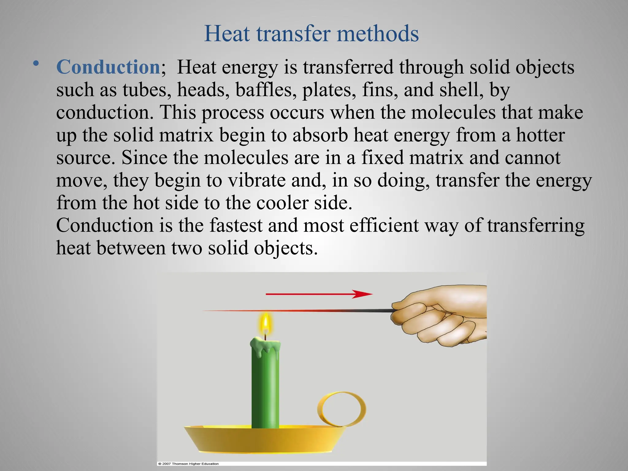
•Conduction; Heat energy is transferred through solid objects
such as tubes, heads, baffles, plates, fins, and shell, by
conduction. This process occurs when the molecules that make
up the solid matrix begin to absorb heat energy from a hotter
source. Since the molecules are in a fixed matrix and cannot
move, they begin to vibrate and, in so doing, transfer the energy
from the hot side to the cooler side.
Conduction is the fastest and most efficient way of transferring
heat between two solid objects.
4.
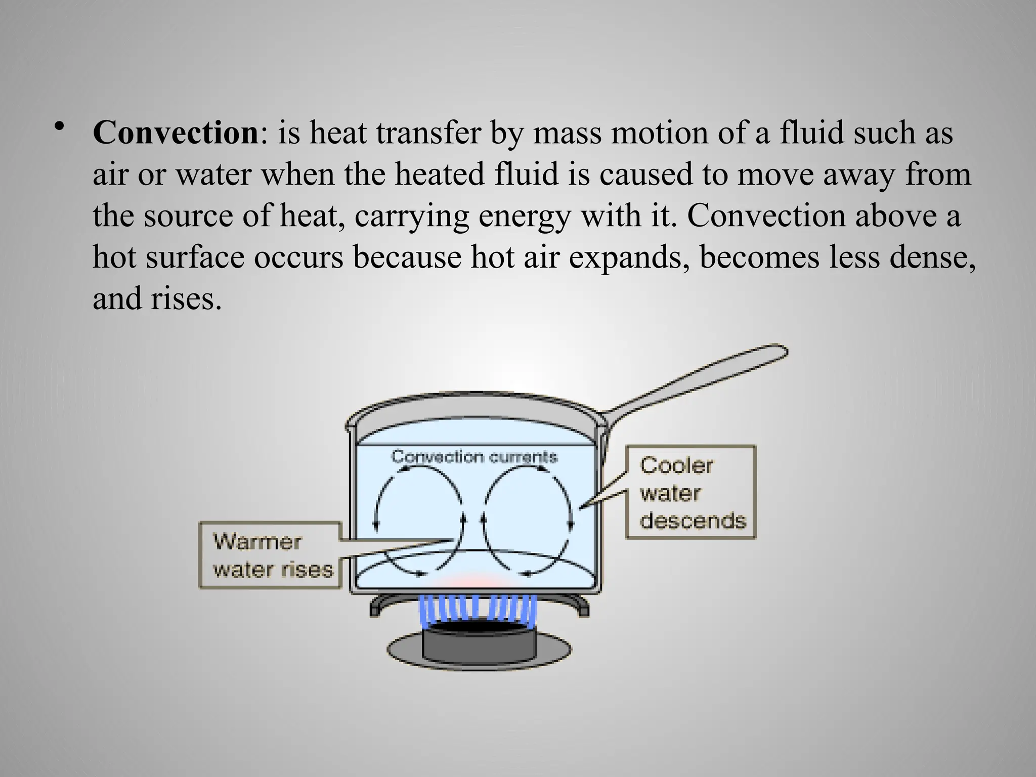
• Convection: isheat transfer by mass motion of a fluid such as
air or water when the heated fluid is caused to move away from
the source of heat, carrying energy with it. Convection above a
hot surface occurs because hot air expands, becomes less dense,
and rises.
5.
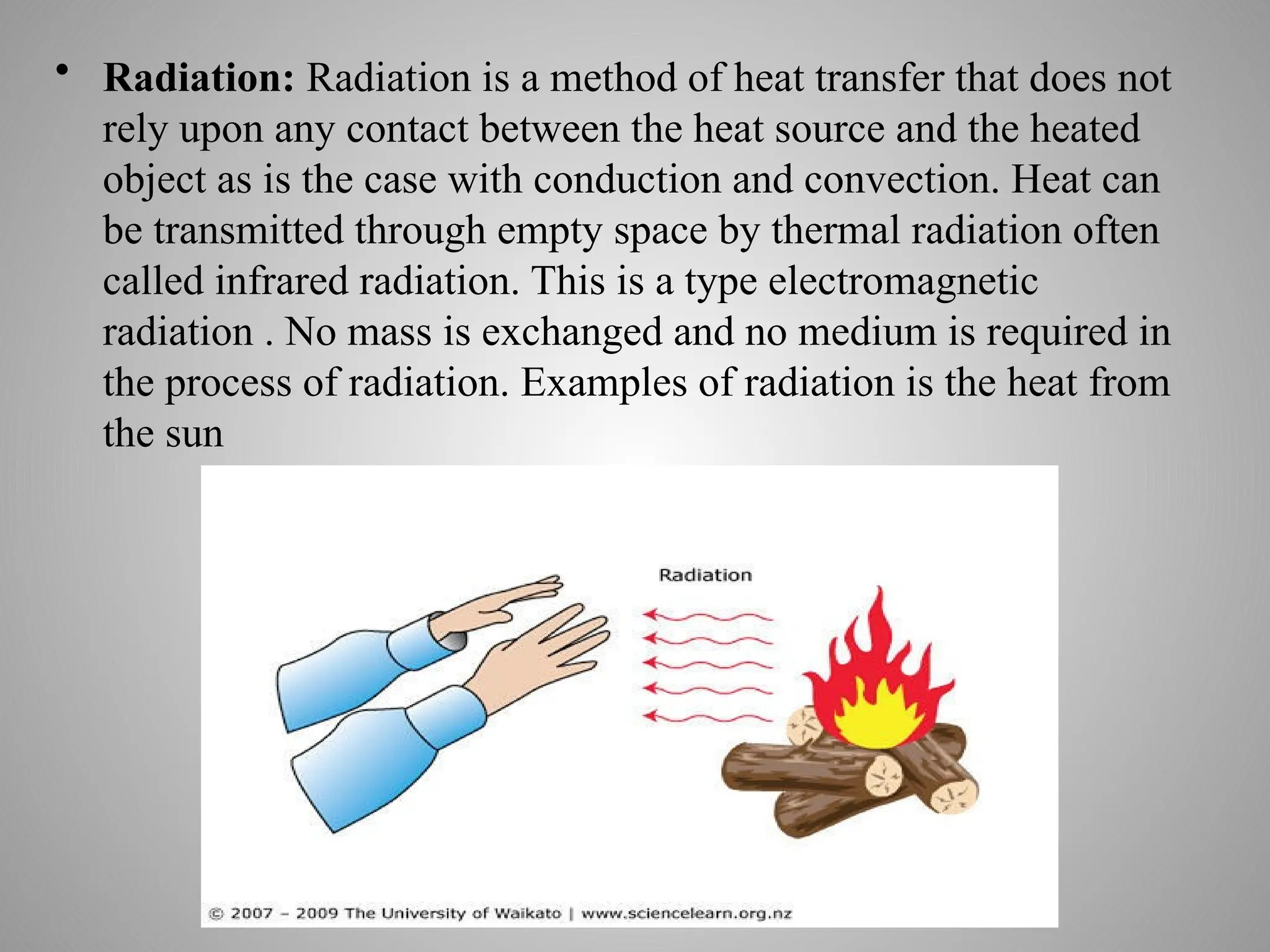
• Radiation: Radiationis a method of heat transfer that does not
rely upon any contact between the heat source and the heated
object as is the case with conduction and convection. Heat can
be transmitted through empty space by thermal radiation often
called infrared radiation. This is a type electromagnetic
radiation . No mass is exchanged and no medium is required in
the process of radiation. Examples of radiation is the heat from
the sun
6.
Types of HeatExchangers
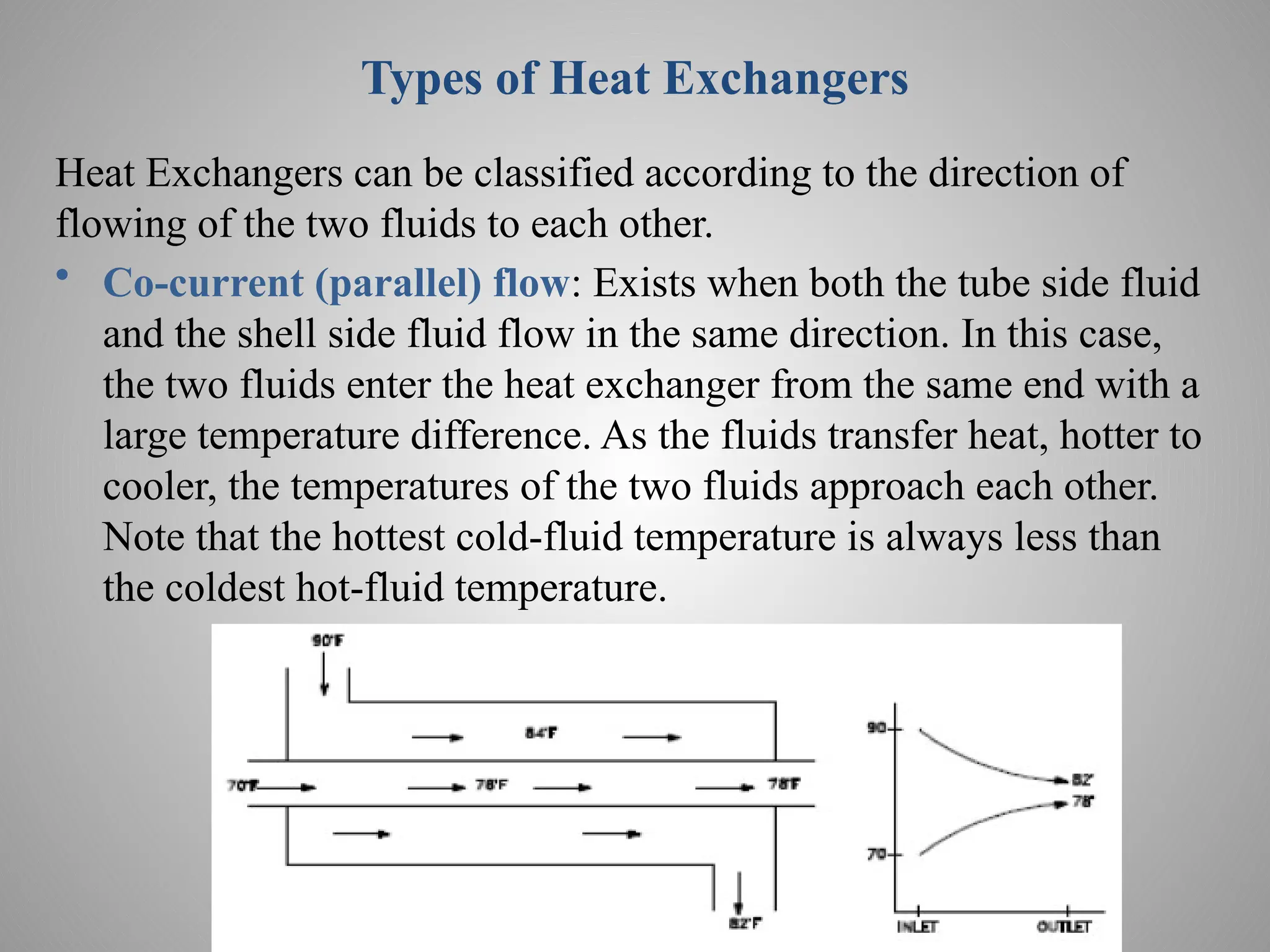
Heat Exchangers can be classified according to the direction of
flowing of the two fluids to each other.
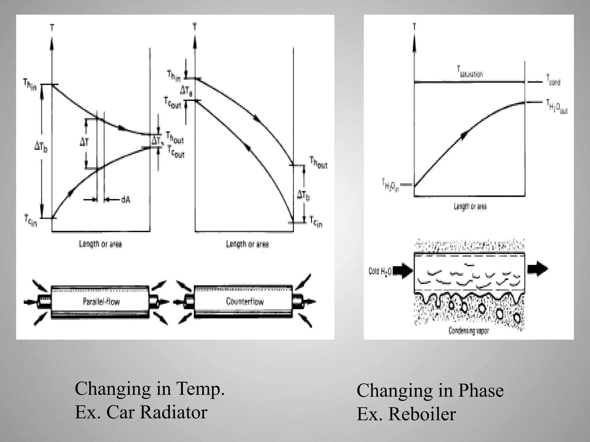
• Co-current (parallel) flow: Exists when both the tube side fluid
and the shell side fluid flow in the same direction. In this case,
the two fluids enter the heat exchanger from the same end with a
large temperature difference. As the fluids transfer heat, hotter to
cooler, the temperatures of the two fluids approach each other.
Note that the hottest cold-fluid temperature is always less than
the coldest hot-fluid temperature.
7.
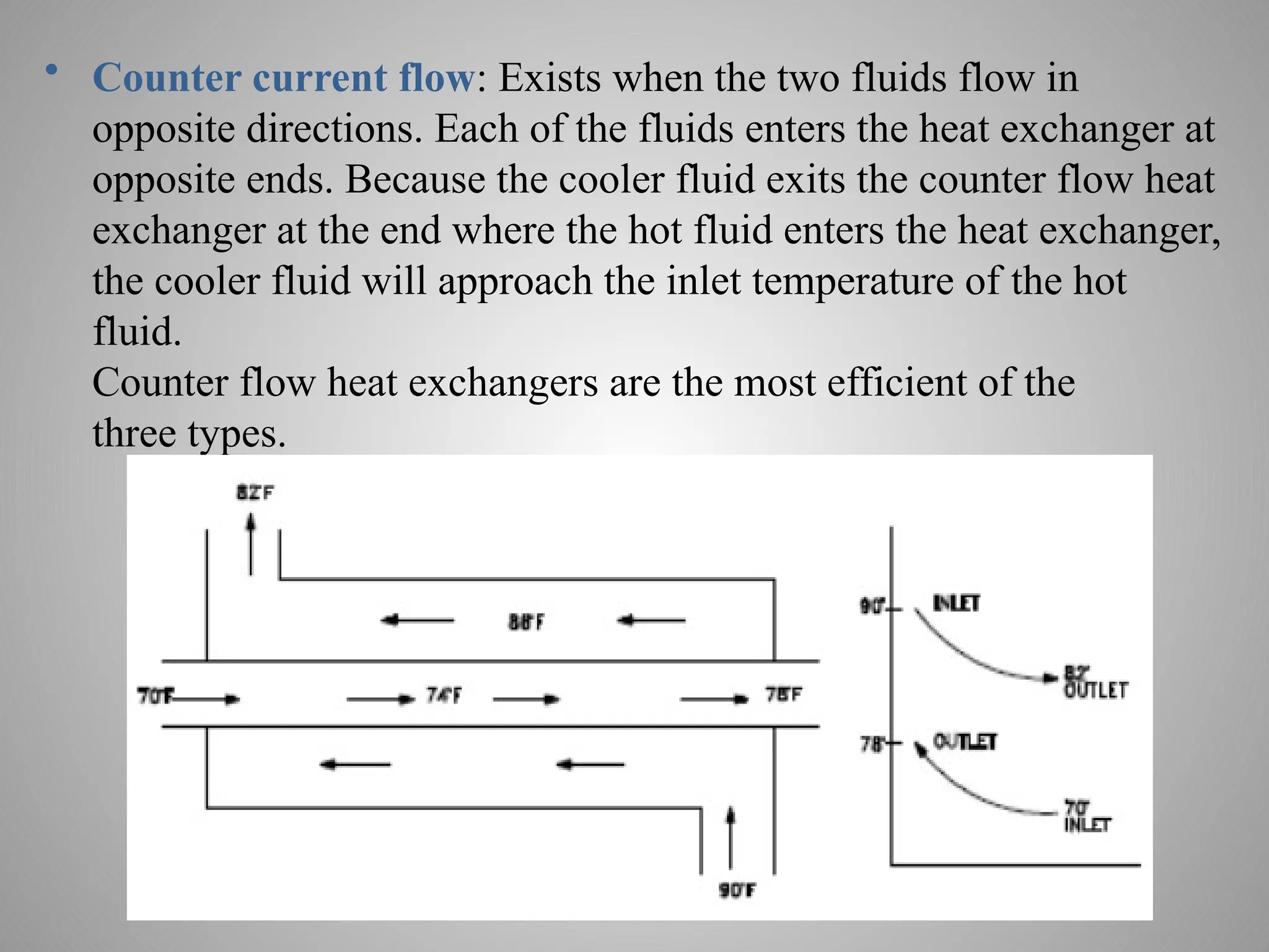
• Counter currentflow: Exists when the two fluids flow in
opposite directions. Each of the fluids enters the heat exchanger at
opposite ends. Because the cooler fluid exits the counter flow heat
exchanger at the end where the hot fluid enters the heat exchanger,
the cooler fluid will approach the inlet temperature of the hot
fluid.
Counter flow heat exchangers are the most efficient of the
three types.
8.
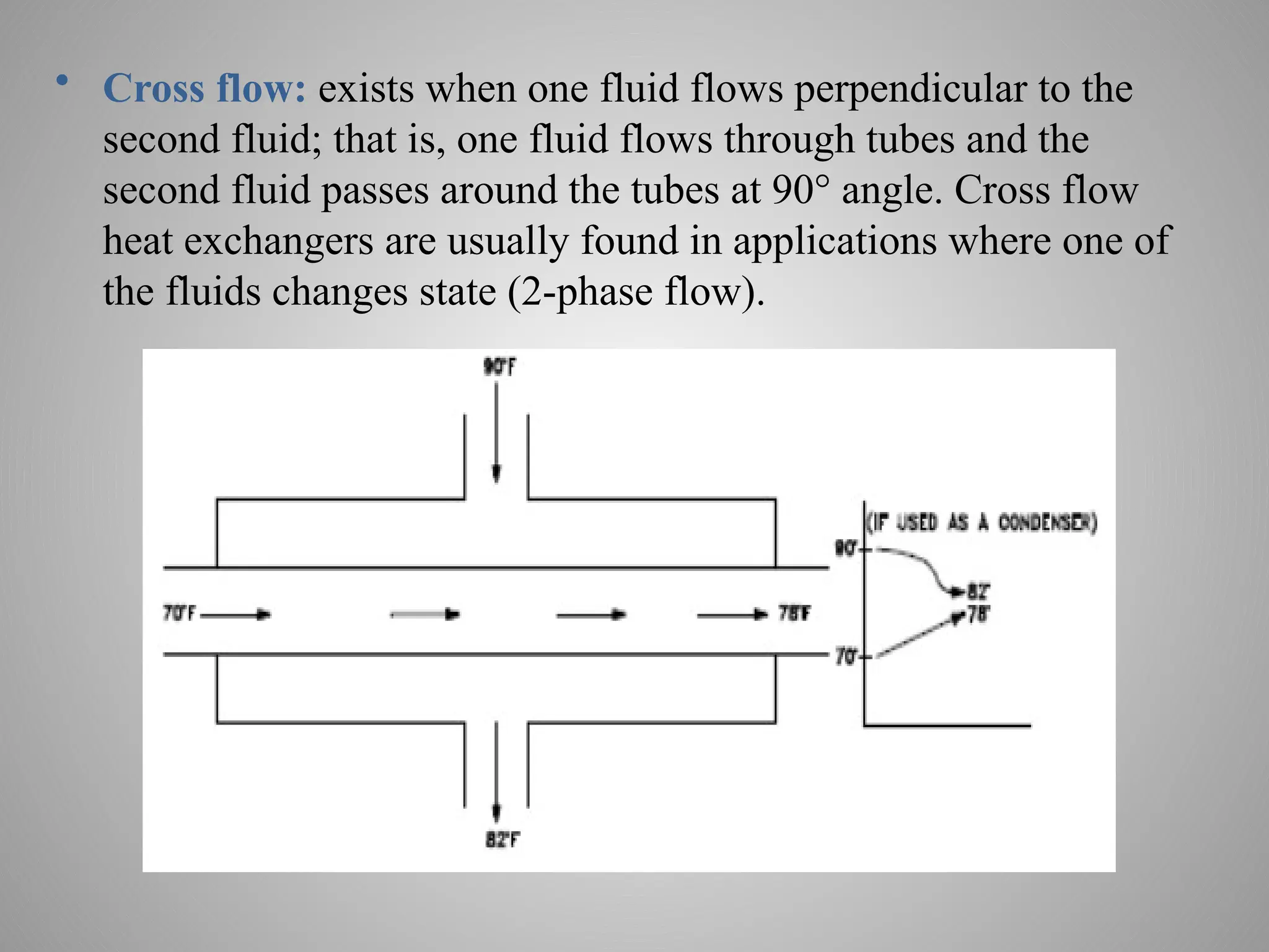
• Cross flow:exists when one fluid flows perpendicular to the
second fluid; that is, one fluid flows through tubes and the
second fluid passes around the tubes at 90° angle. Cross flow
heat exchangers are usually found in applications where one of
the fluids changes state (2-phase flow).
9.
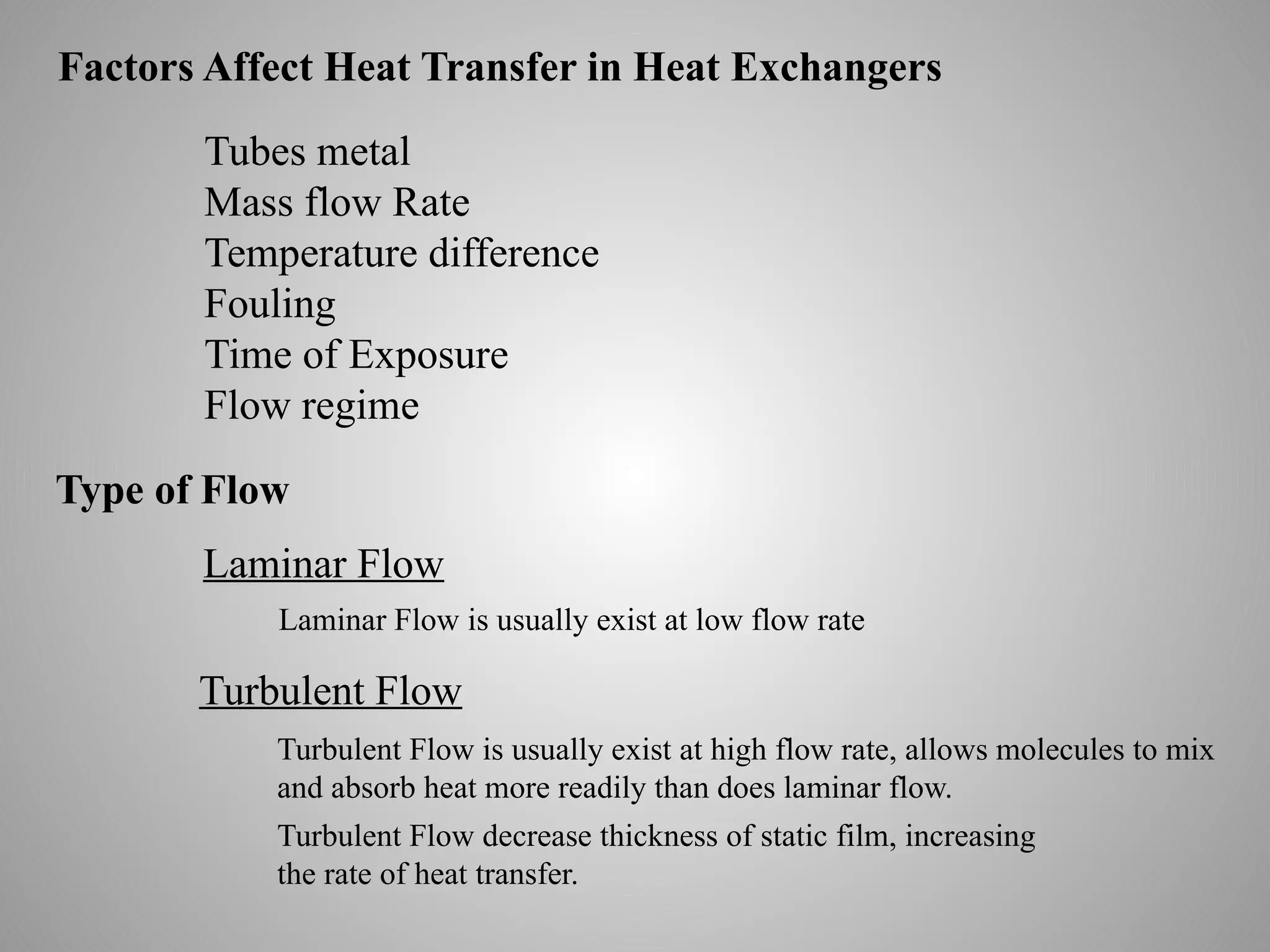
Factors Affect HeatTransfer in Heat Exchangers
Tubes metal
Mass flow Rate
Temperature difference
Fouling
Time of Exposure
Flow regime
Type of Flow
Laminar Flow
Turbulent Flow
Laminar Flow is usually exist at low flow rate
Turbulent Flow is usually exist at high flow rate, allows molecules to mix
and absorb heat more readily than does laminar flow.
Turbulent Flow decrease thickness of static film, increasing
the rate of heat transfer.
10.
10
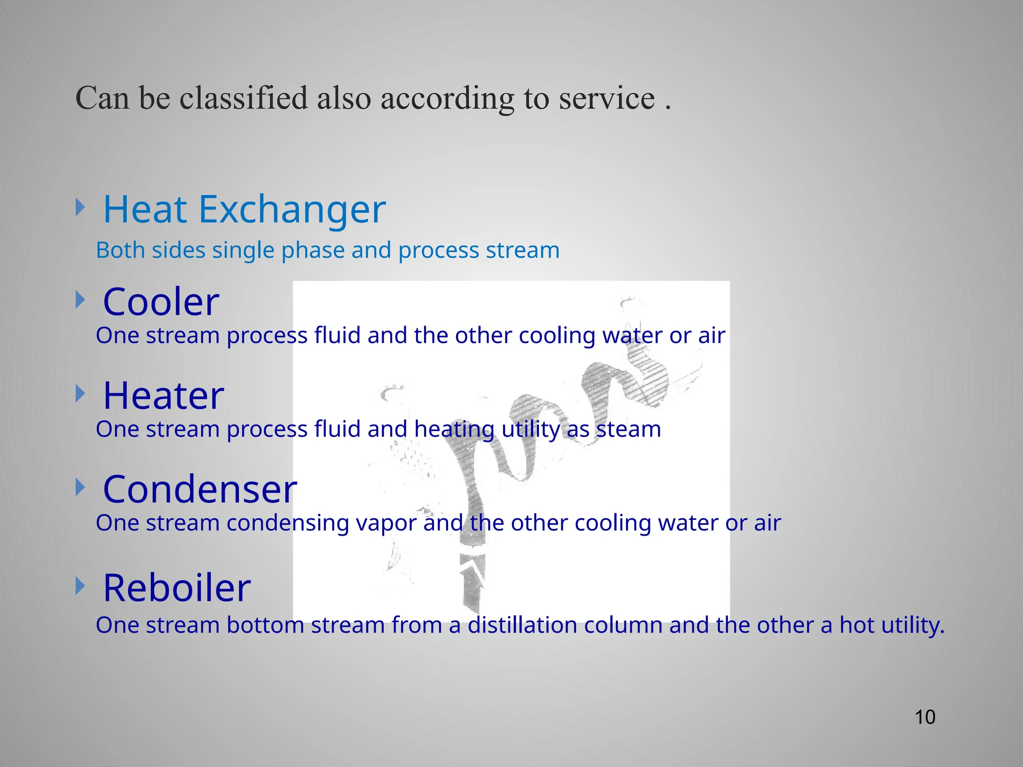
Heat Exchanger
Cooler
Heater
Condenser
Reboiler
Both sides single phase and process stream
One stream process fluid and the other cooling water or air
One stream process fluid and heating utility as steam
One stream condensing vapor and the other cooling water or air
One stream bottom stream from a distillation column and the other a hot utility.
Can be classified also according to service .
11.
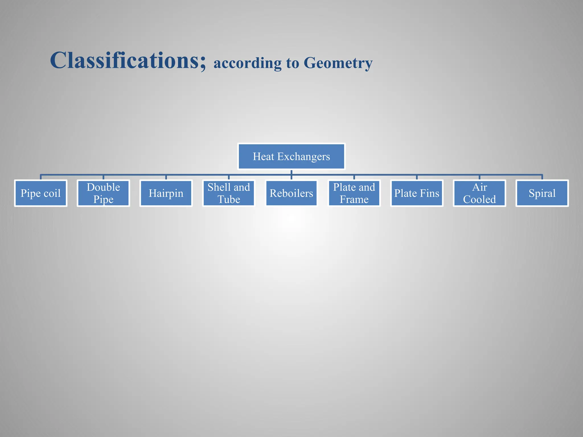
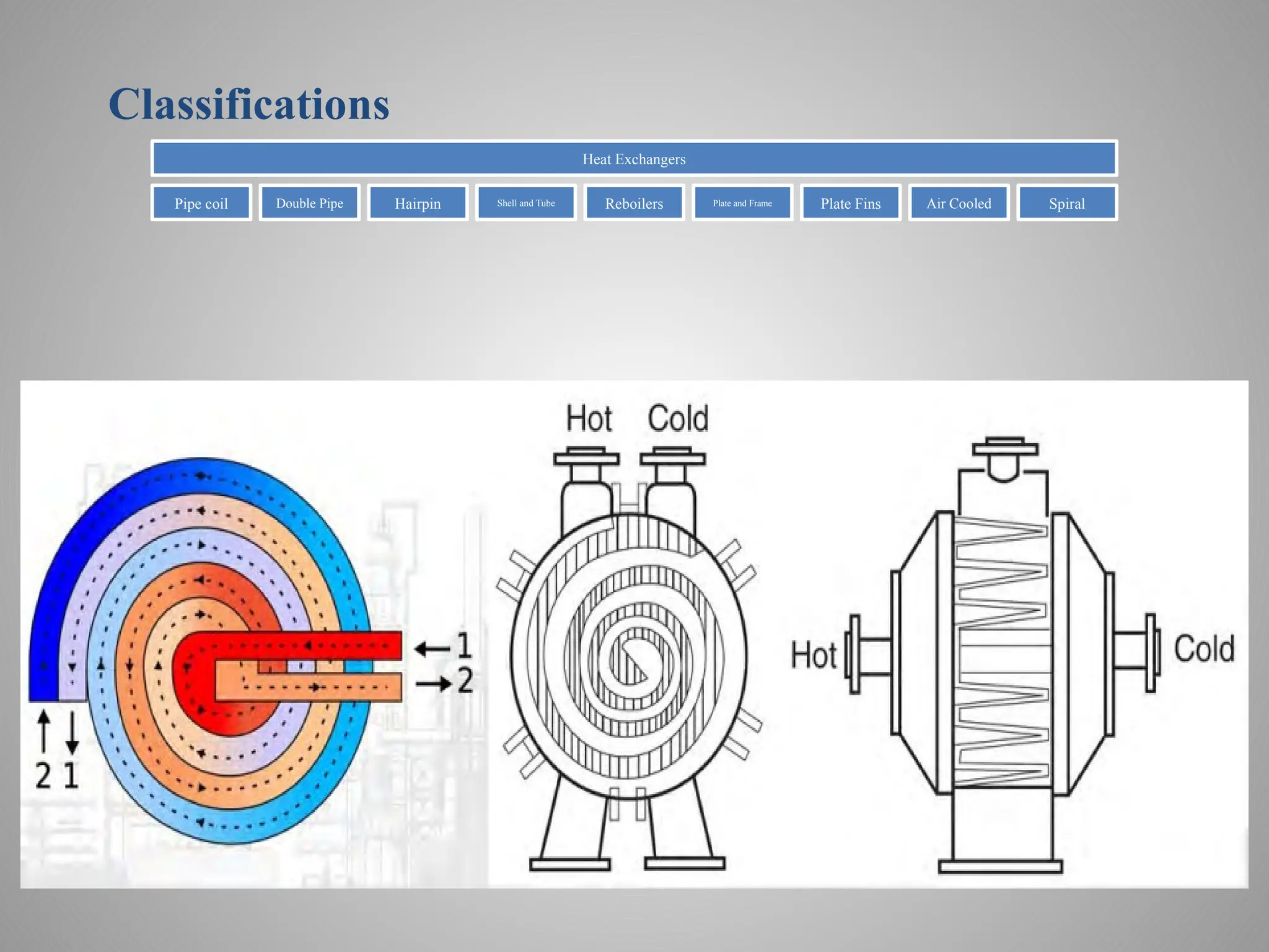
Classifications; according toGeometry
Heat Exchangers
Pipe coil
Double
Pipe
Hairpin
Shell and
Tube
Reboilers
Plate and
Frame
Plate Fins
Air
Cooled
Spiral
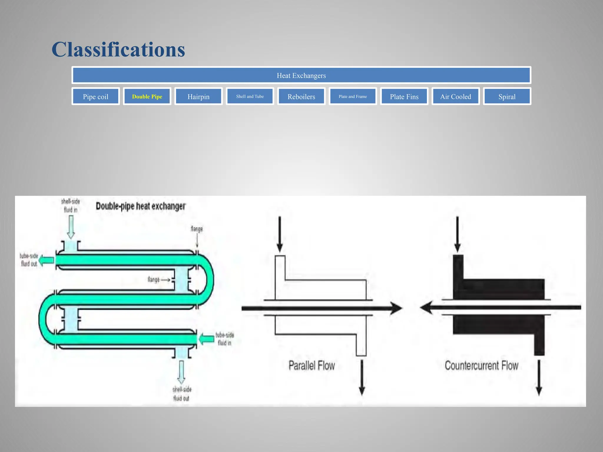
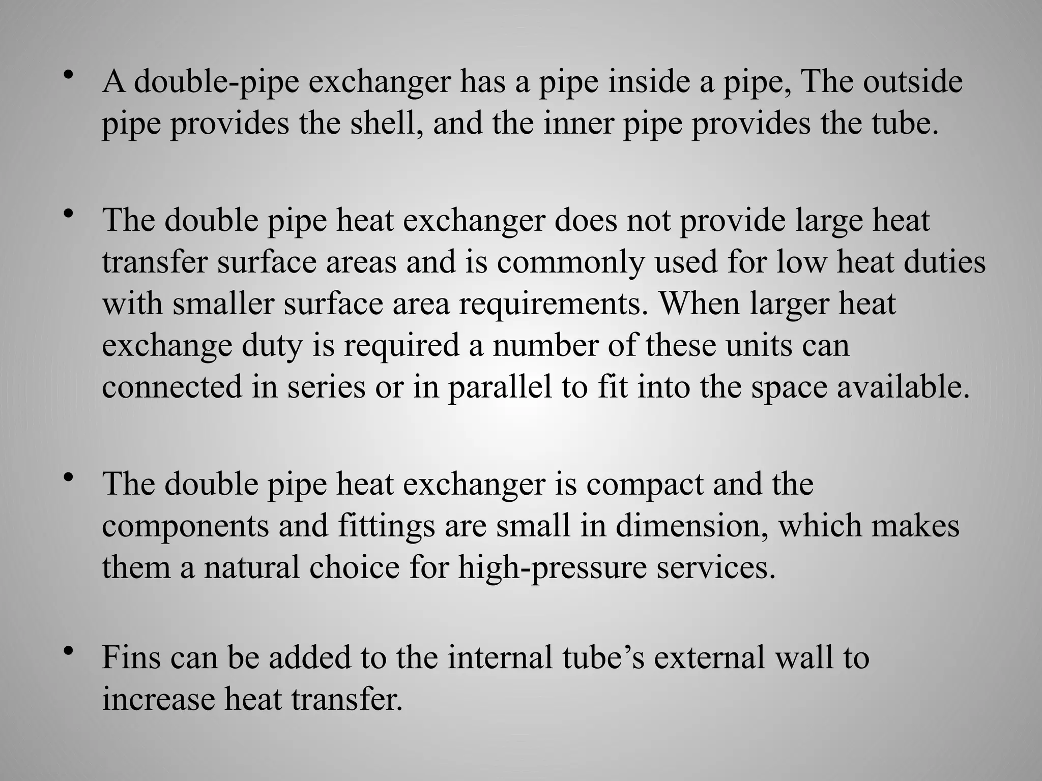
• A double-pipeexchanger has a pipe inside a pipe, The outside
pipe provides the shell, and the inner pipe provides the tube.
• The double pipe heat exchanger does not provide large heat
transfer surface areas and is commonly used for low heat duties
with smaller surface area requirements. When larger heat
exchange duty is required a number of these units can
connected in series or in parallel to fit into the space available.
• The double pipe heat exchanger is compact and the
components and fittings are small in dimension, which makes
them a natural choice for high-pressure services.
• Fins can be added to the internal tube’s external wall to
increase heat transfer.
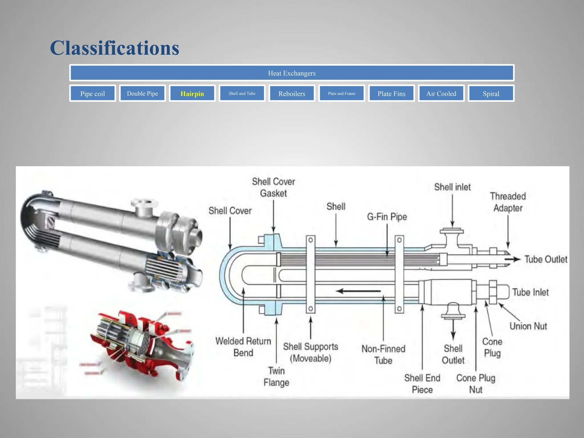
• The hairpin(Multi-pipe) resembles a typical shell-and-tube heat
exchanger, stretched and bent into a hairpin.
• excellent capacity for thermal expansion because of
its U-tube type shape.
• its finned design, which works well with fluids that have a low
heat transfer coefficient.
• its high pressure on the tube side.
• it is easy to install and clean; its modular design makes it easy
to add new sections.
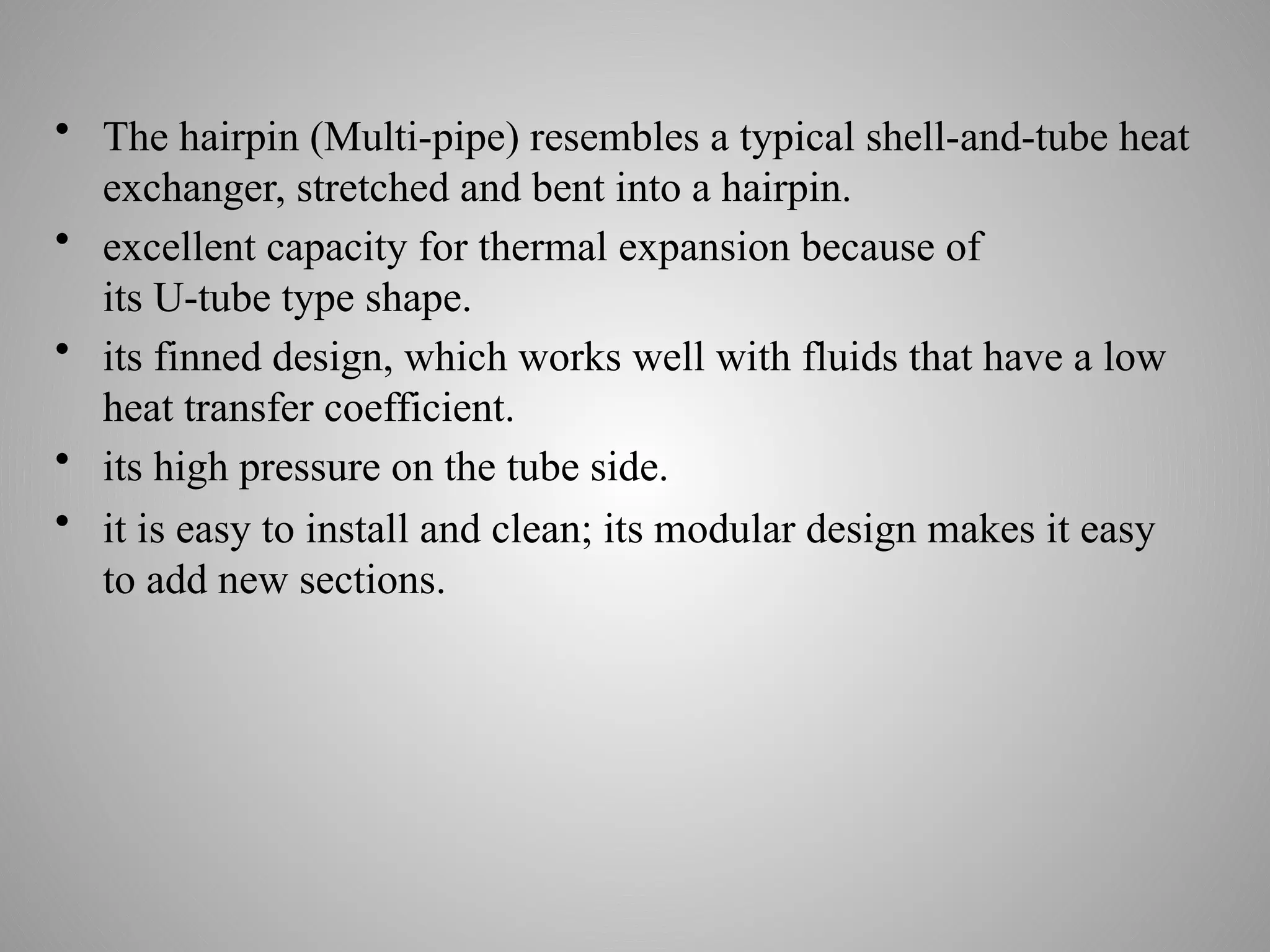
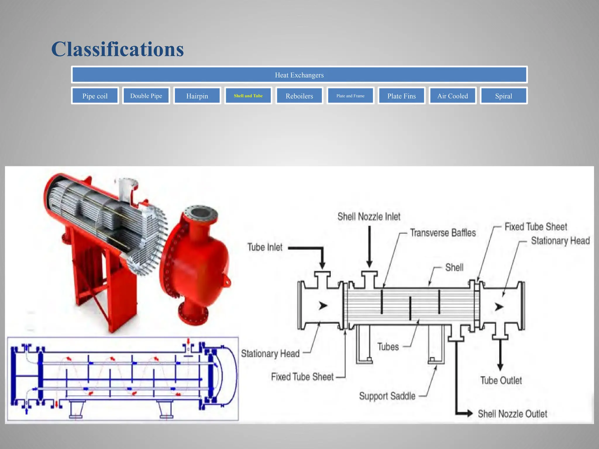
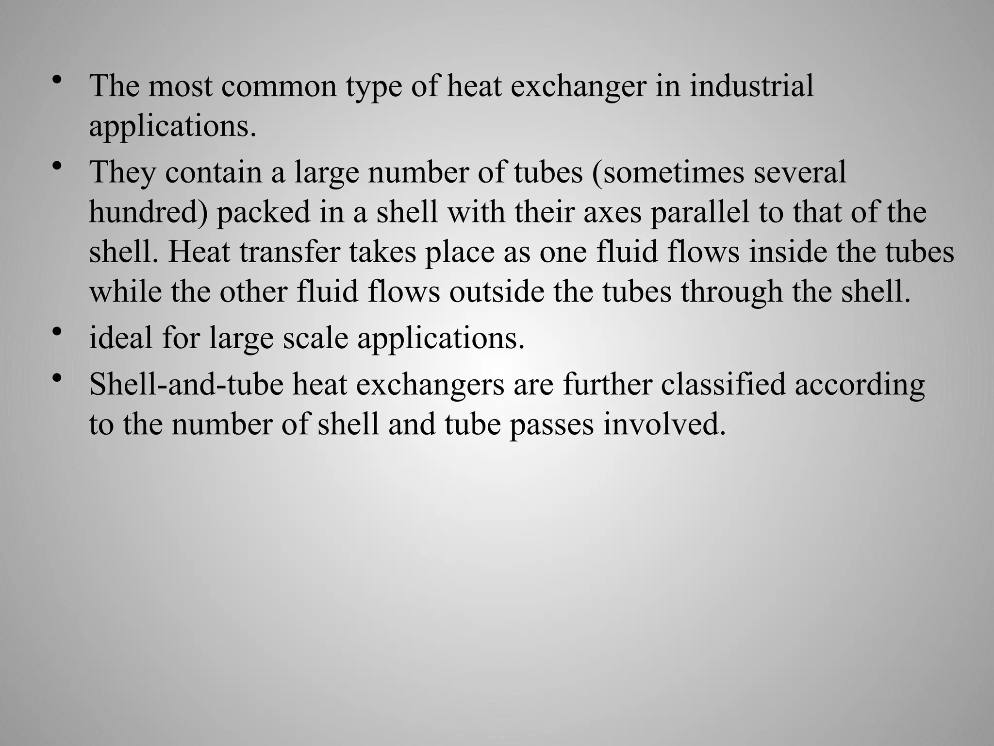
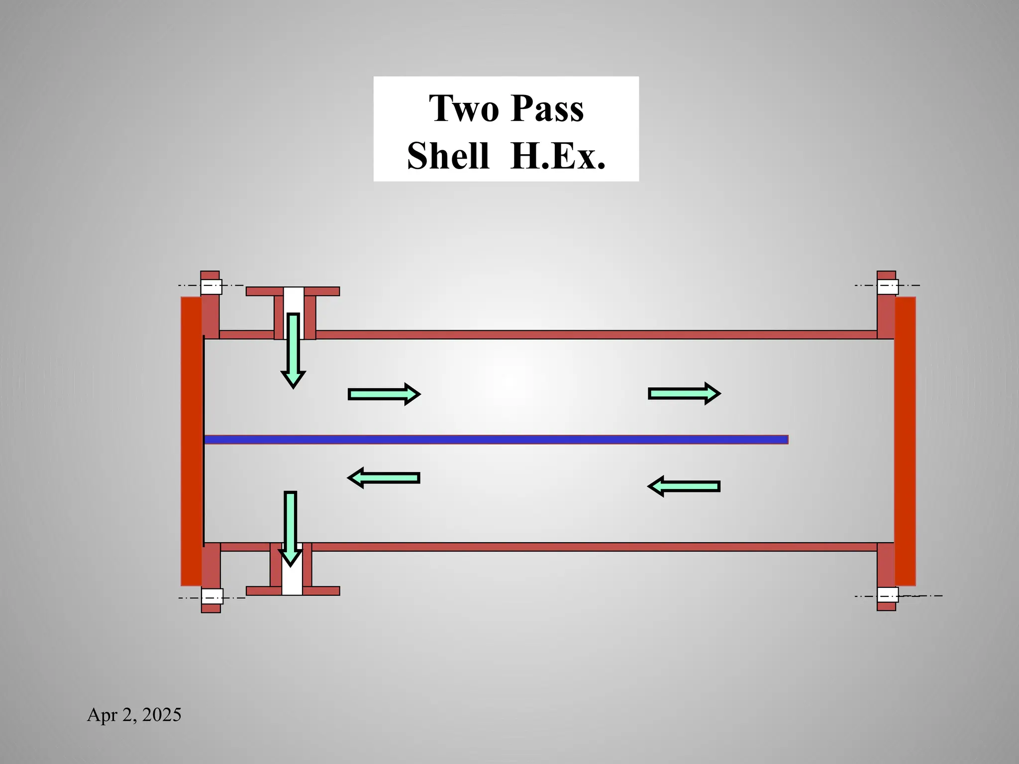
• The mostcommon type of heat exchanger in industrial
applications.
• They contain a large number of tubes (sometimes several
hundred) packed in a shell with their axes parallel to that of the
shell. Heat transfer takes place as one fluid flows inside the tubes
while the other fluid flows outside the tubes through the shell.
• ideal for large scale applications.
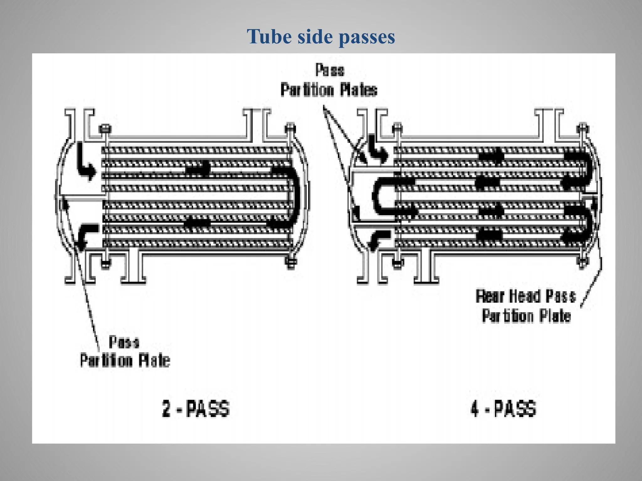
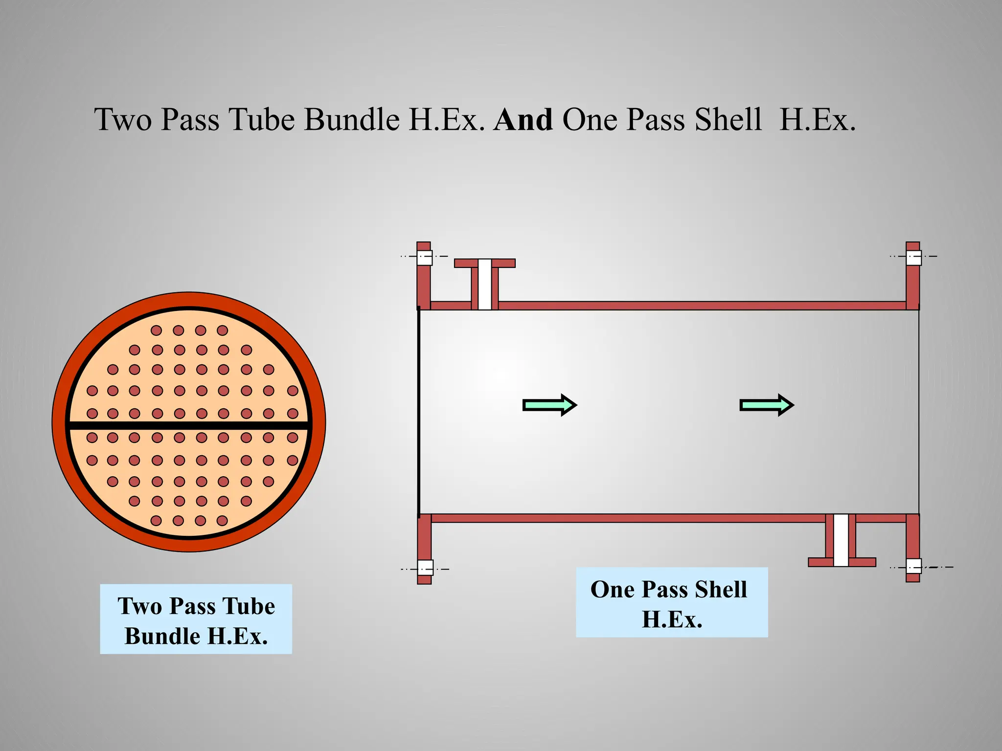
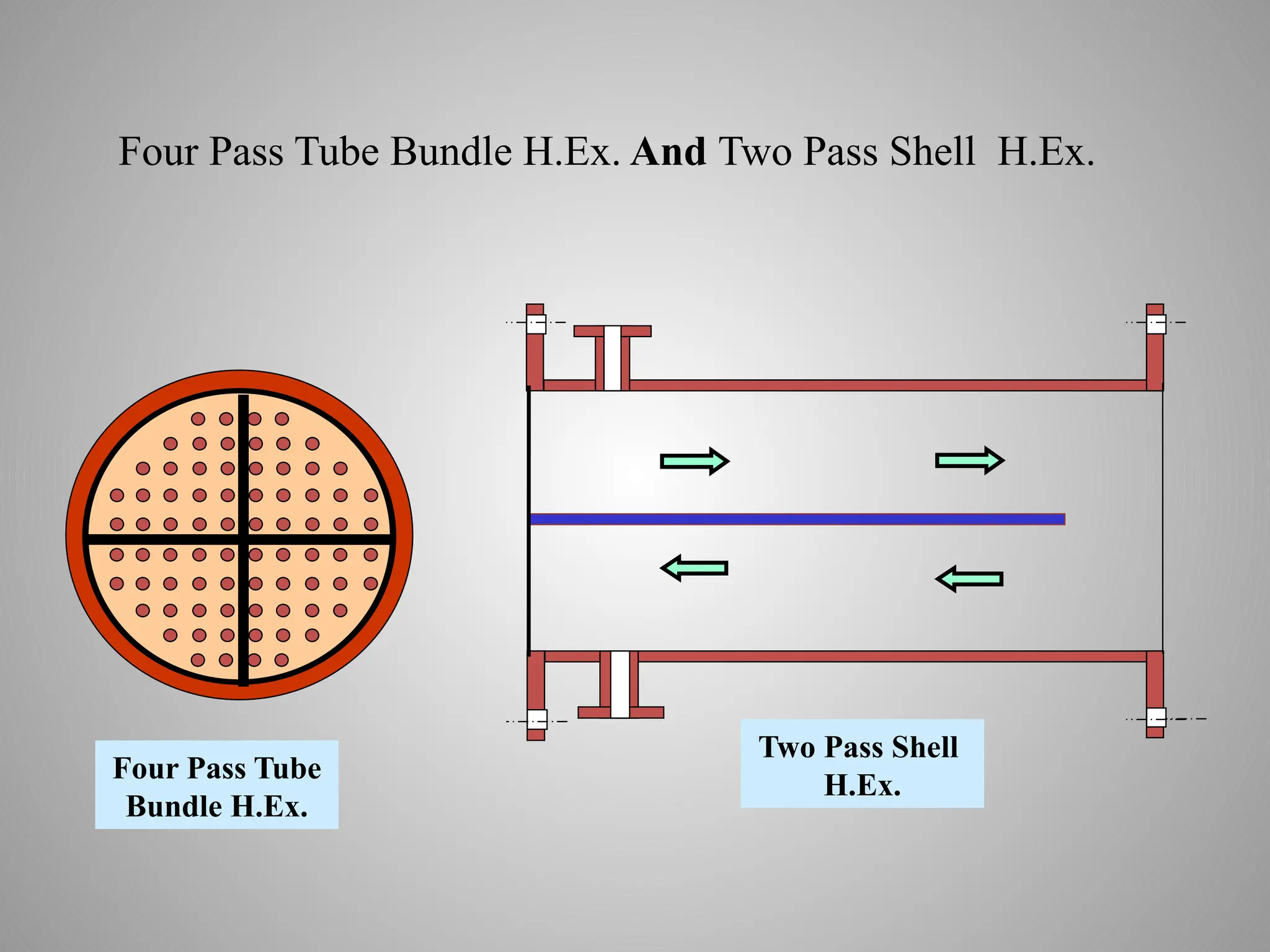
• Shell-and-tube heat exchangers are further classified according
to the number of shell and tube passes involved.
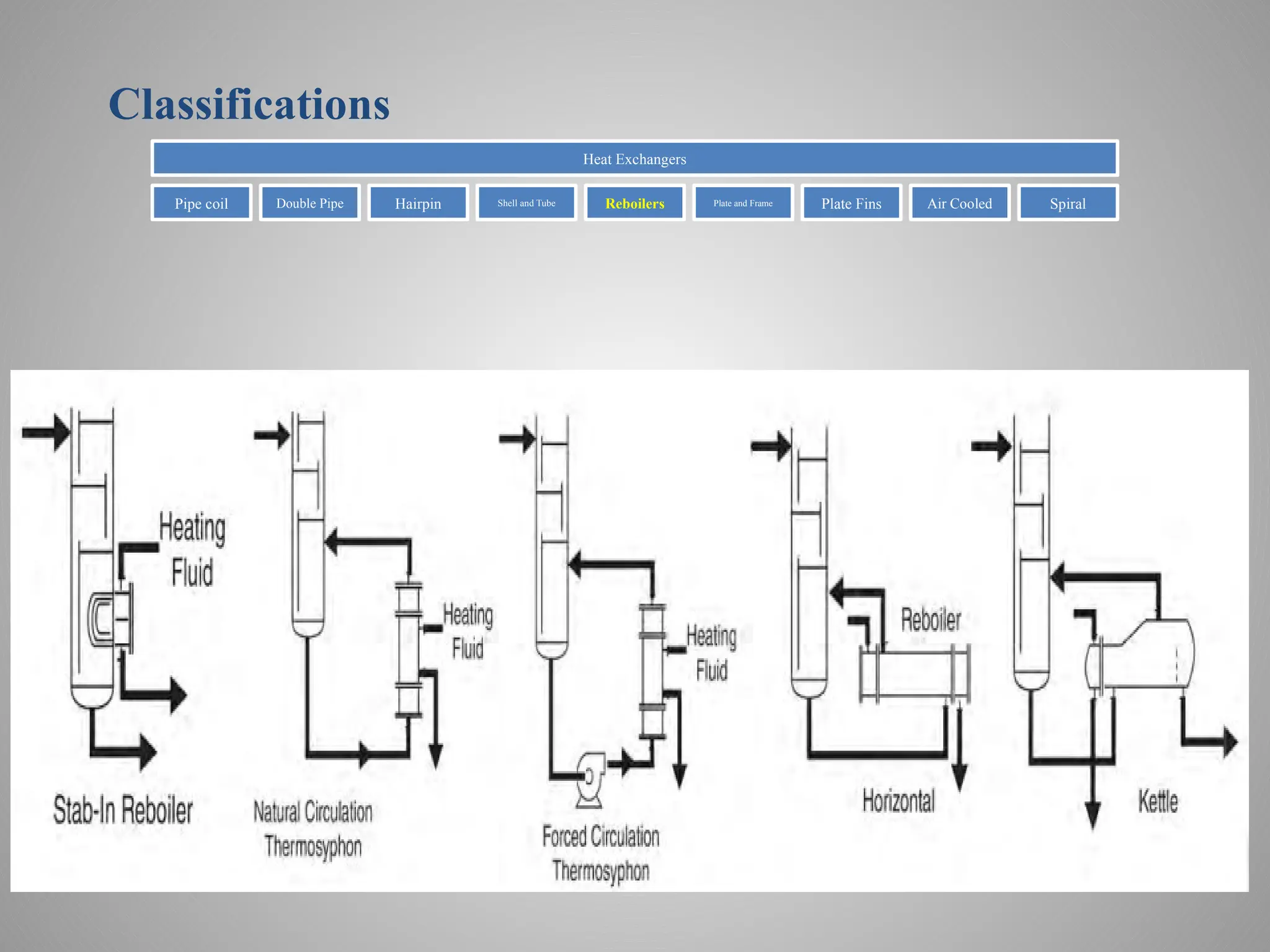
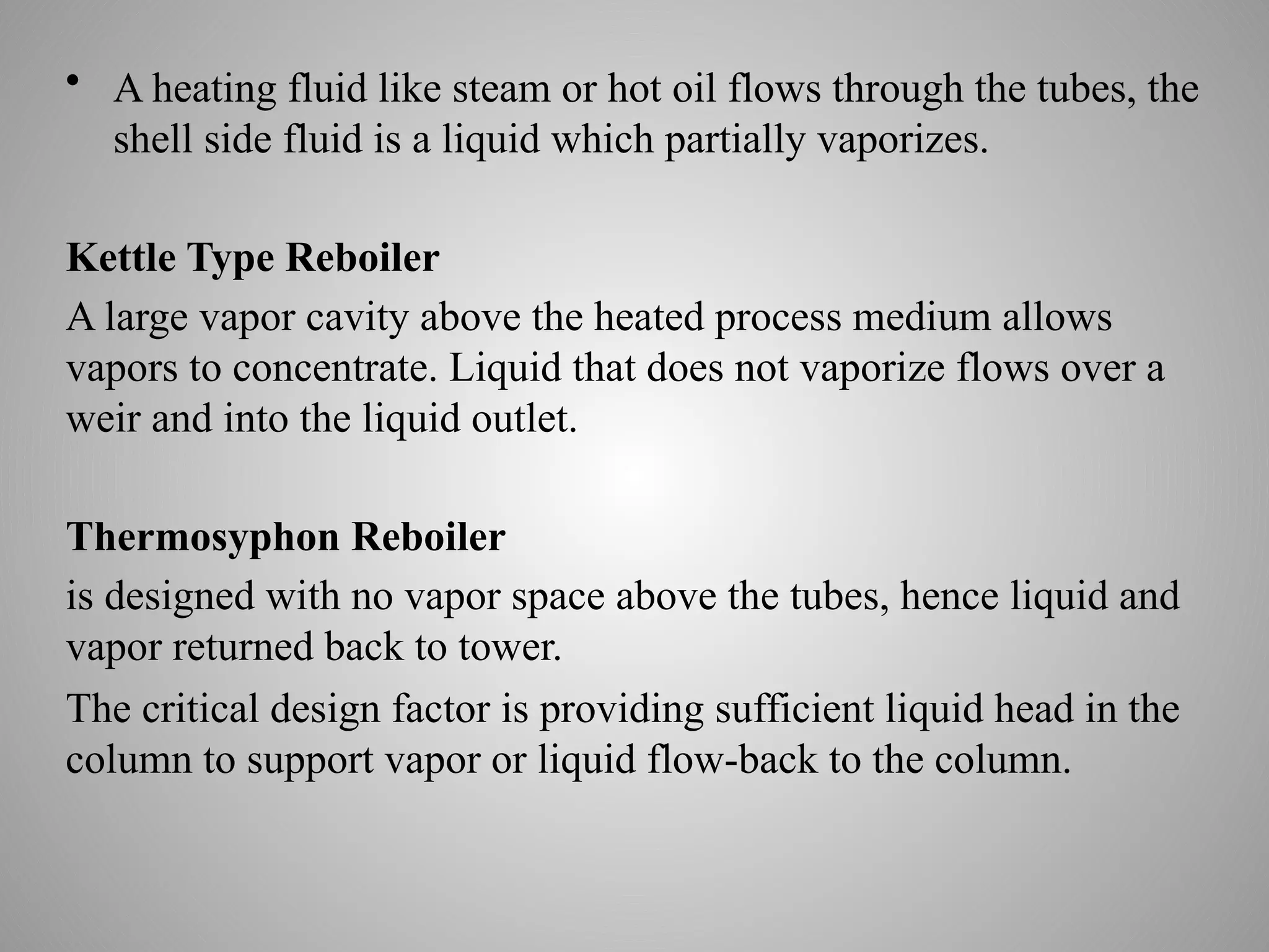
• A heatingfluid like steam or hot oil flows through the tubes, the
shell side fluid is a liquid which partially vaporizes.
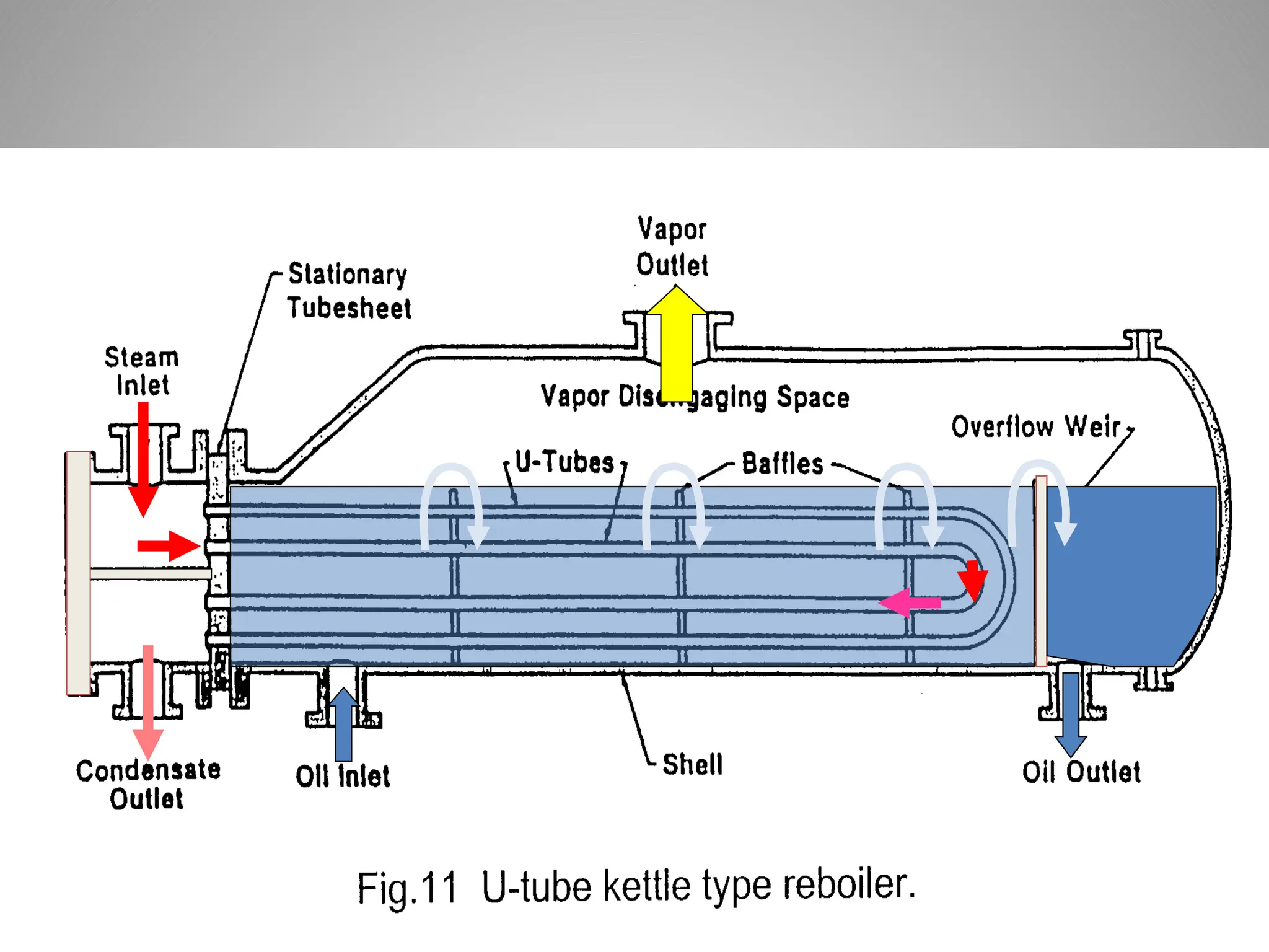
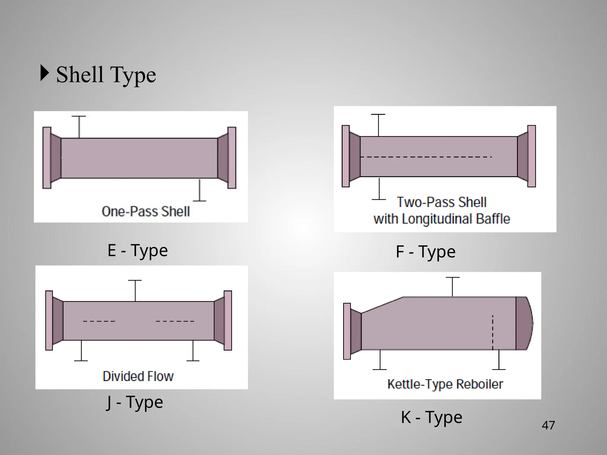
Kettle Type Reboiler
A large vapor cavity above the heated process medium allows
vapors to concentrate. Liquid that does not vaporize flows over a
weir and into the liquid outlet.
Thermosyphon Reboiler
is designed with no vapor space above the tubes, hence liquid and
vapor returned back to tower.
The critical design factor is providing sufficient liquid head in the
column to support vapor or liquid flow-back to the column.
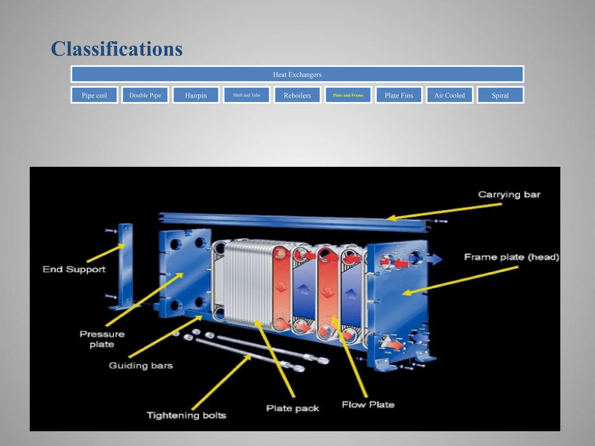
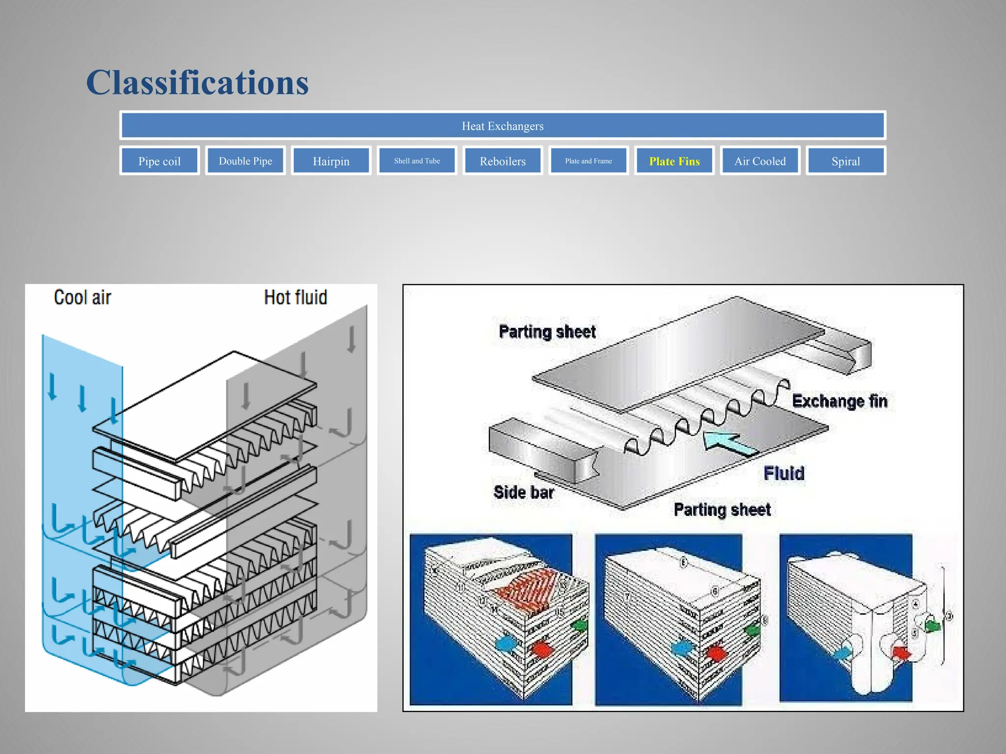
• Plate heatexchangers (PHE) have a number of pressed metal
plates, aligned on a frame clamped together with gaskets
between the plates.
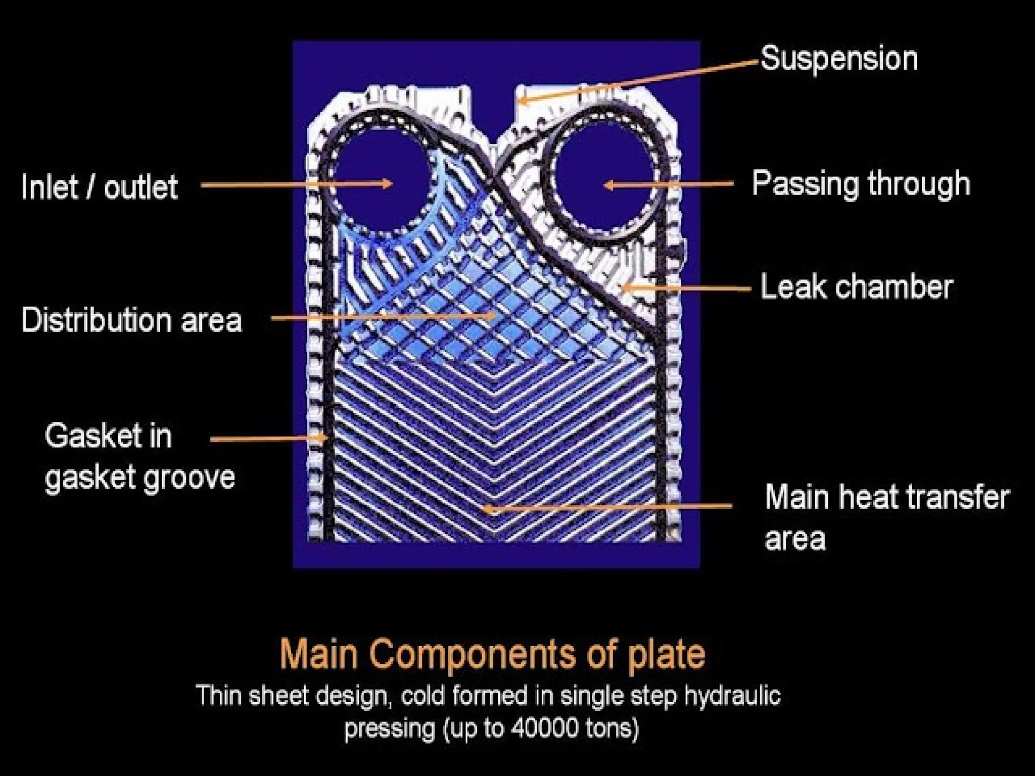
• Each pressed plate is corrugated, having a alternating ridges and
grooves.
• The fluids flow between alternating plates. The flow distribution
depends upon the opening of the circumferential gasket (gasket
running around the outside of the plates) to an inlet or outlet
port. Circumferential gaskets surround the inlet and outlet ports.
These gaskets prevent mixing of the exchanger fluids.
• The corrugated plates create turbulence, which also promotes
high heat transfer rates, by continuously altering the flow
direction and velocity of the fluids.
Plate frame heat exchanger
25.
• Easy toRemove and Clean
Plate Heat Exchangers are easy to clean by remove the tie bolts and
slide back the movable frame part. Then the plate pack can be
inspected, pressure cleaned, or removed for refurbishment if required.
• Expandable
A very significant feature of the plate Heat Exchanger is that it is
expandable. Increasing the Heat Transfer requirements means simply
adding plates instead of buying a new Heat Exchanger, saving time
and money.
• High Efficiency
Because of the pressed patterns in the plates and the relative narrow
gaps, very high turbulence is achieved at relative low fluid velocity.
This combined with counter directional flow results in very high
Heat Transfer coefficients.
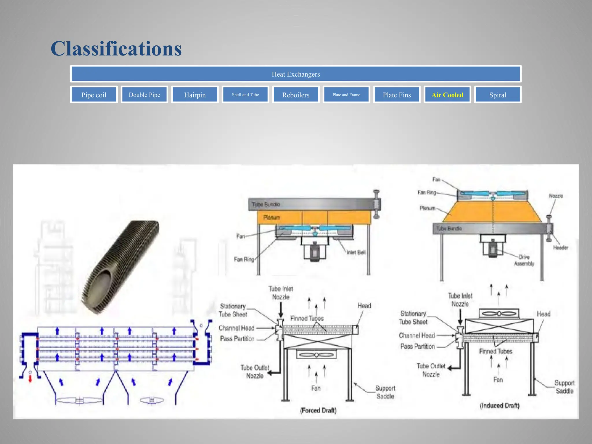
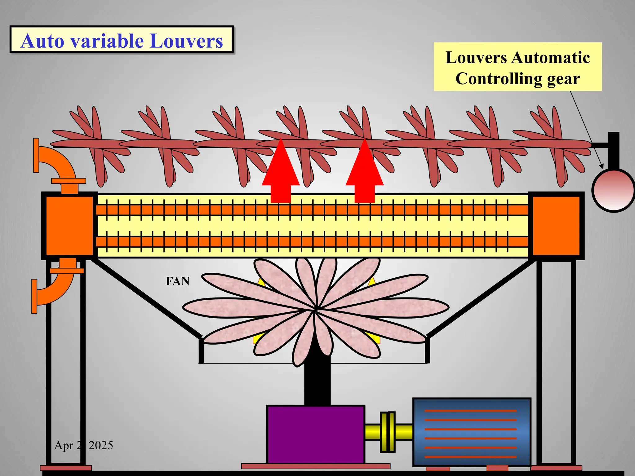
• Air isused as the outside medium to transfer heat away from
the tubes.
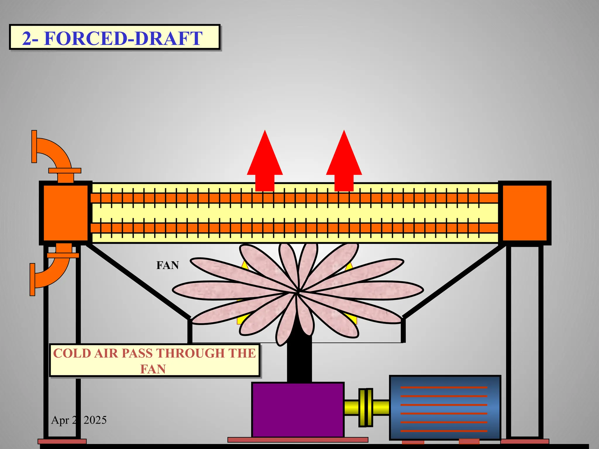
• Fans can be mounted above or below the tubes in forced-draft
or induced-draft arrangements.
• Air-cooled heat exchangers can be found in service on air
compressors, in recirculation systems, and in condensing
operations.
• The aerial cooler is preferred for processes where the
temperature of fluids to be cooled is at least 55°C. They are also
used where fouling of the tubes on the cooling waterside of a
water-cooled exchanger is a concern. If a fluid stream at a high
temperature requires cooling below the ambient temperature, a
combination of aerial cooling followed by water-cooling will
often prove to be efficient and economical since a large portion
of the heat load is removed before the water is used.
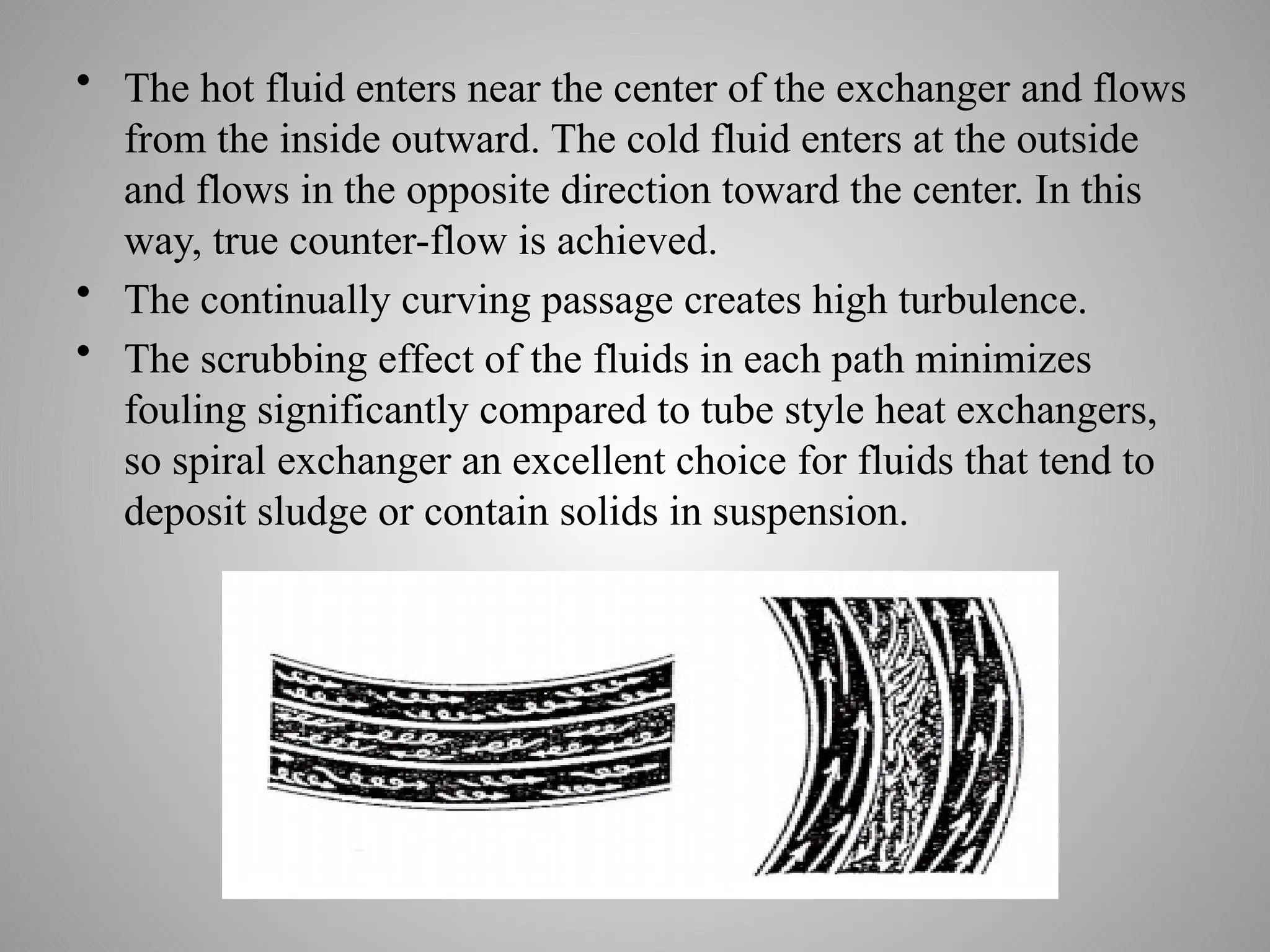
• The hotfluid enters near the center of the exchanger and flows
from the inside outward. The cold fluid enters at the outside
and flows in the opposite direction toward the center. In this
way, true counter-flow is achieved.
• The continually curving passage creates high turbulence.
• The scrubbing effect of the fluids in each path minimizes
fouling significantly compared to tube style heat exchangers,
so spiral exchanger an excellent choice for fluids that tend to
deposit sludge or contain solids in suspension.
33.
Heat Exchangers areclassified according to their function:
Recuperative:
two fluids separated by a solid wall (this is the most common type)
Evaporative:
Enthalpy of evaporation of one fluid is used to heat or cool the
other fluid (condensers/evaporators and boilers)
Regenerative:
use a third material which stores/releases heat
Apr 2, 2025
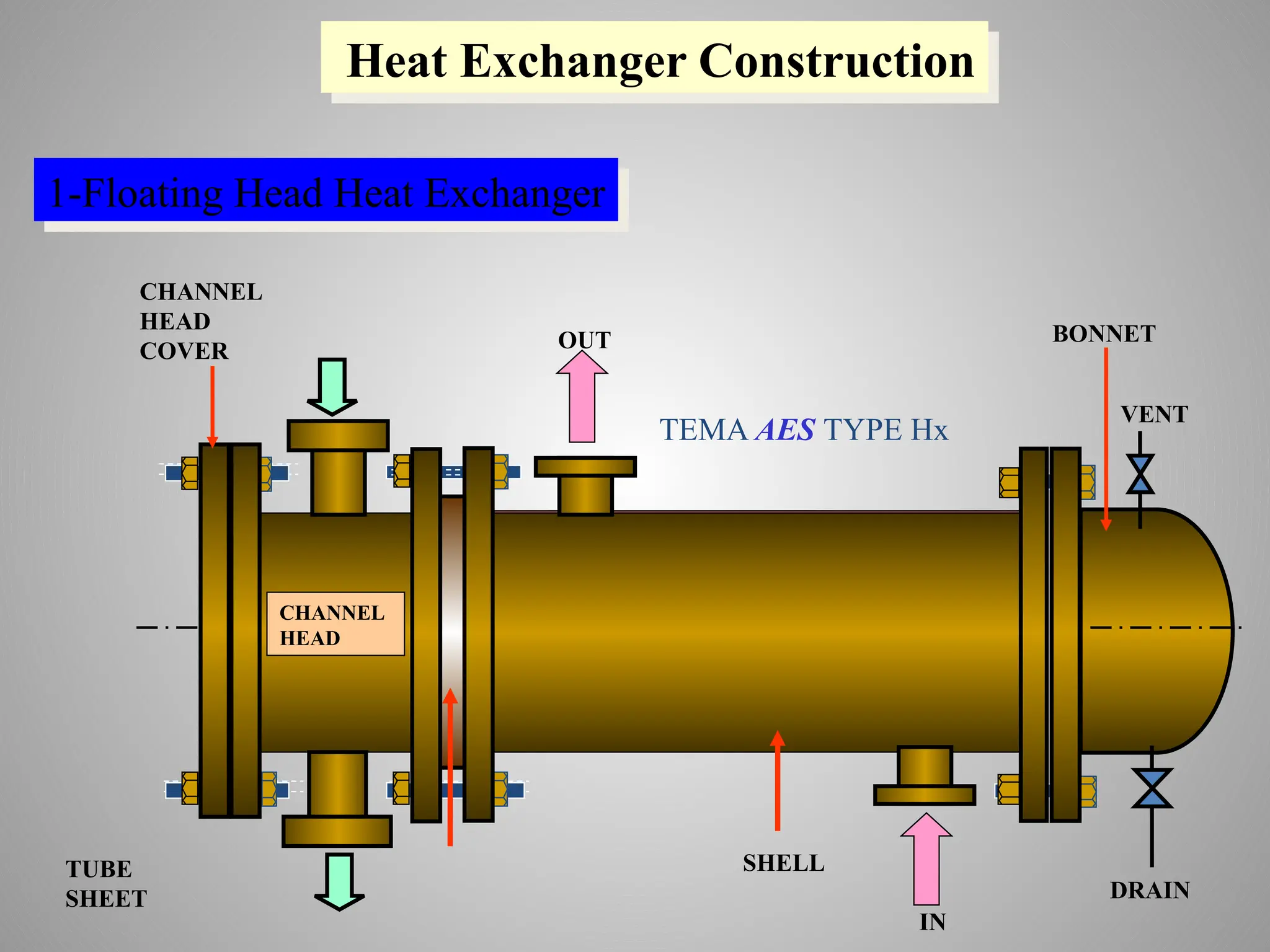
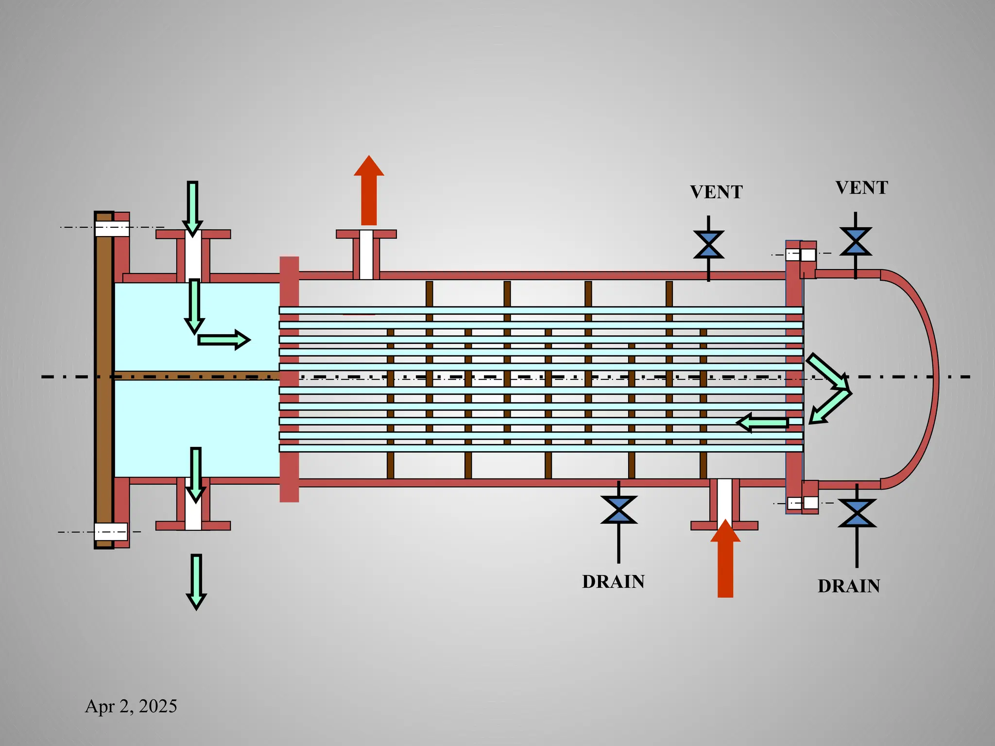
VENT
DRAIN
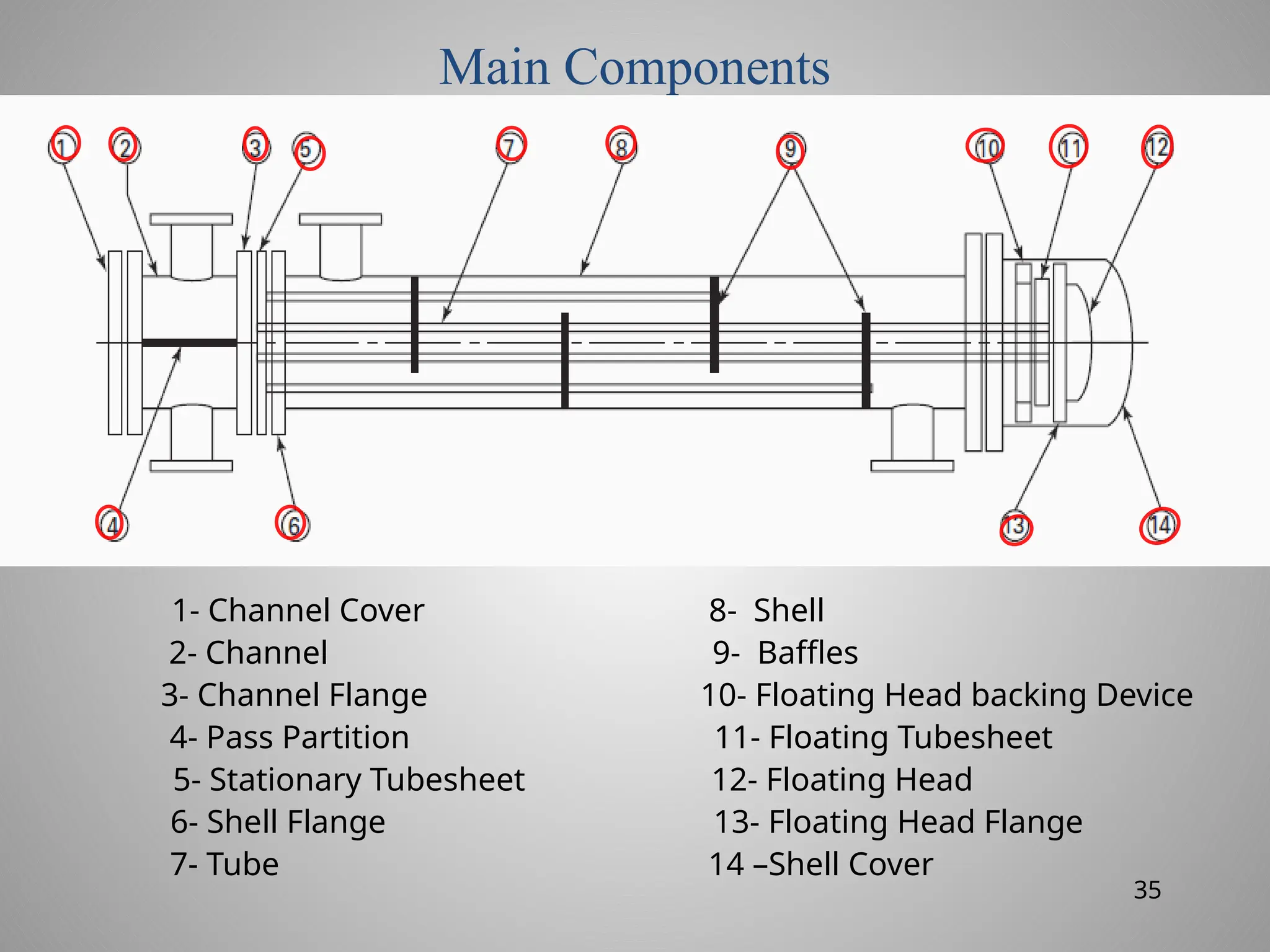
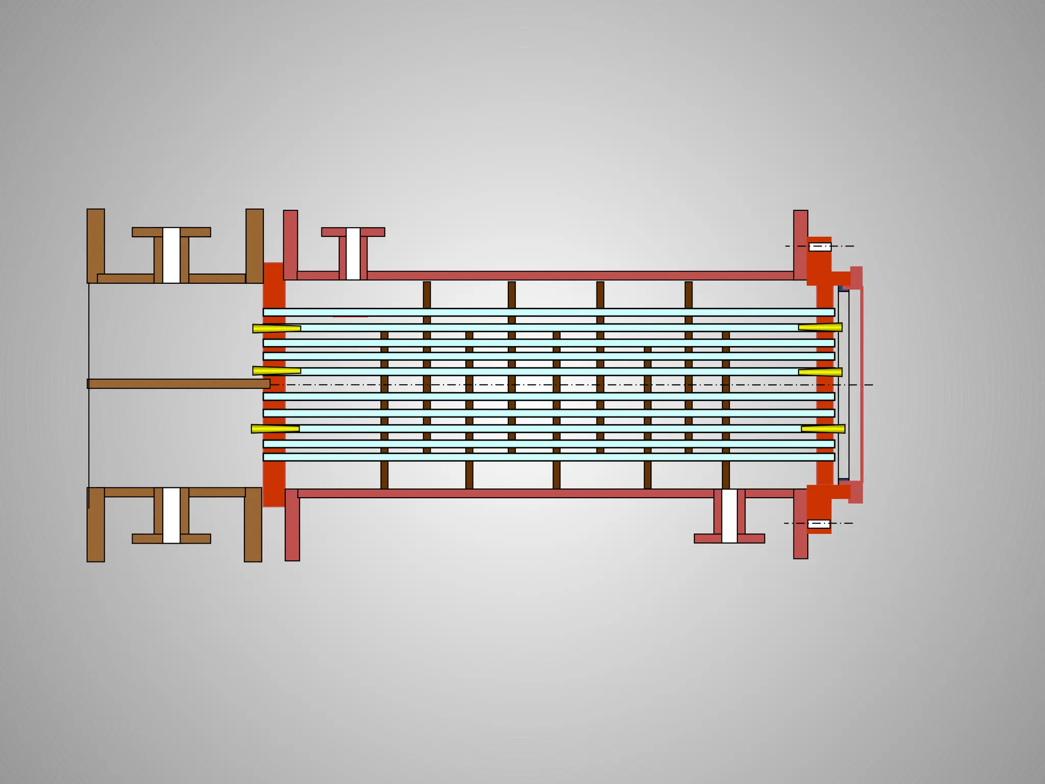
TUBE
SHEET
SHELL
FLOATIN
GHEAD
TUBE
BUNDLE
CHANNEL
HEAD
TUBE
HEAD
COVER
BAFFLE
PLATES
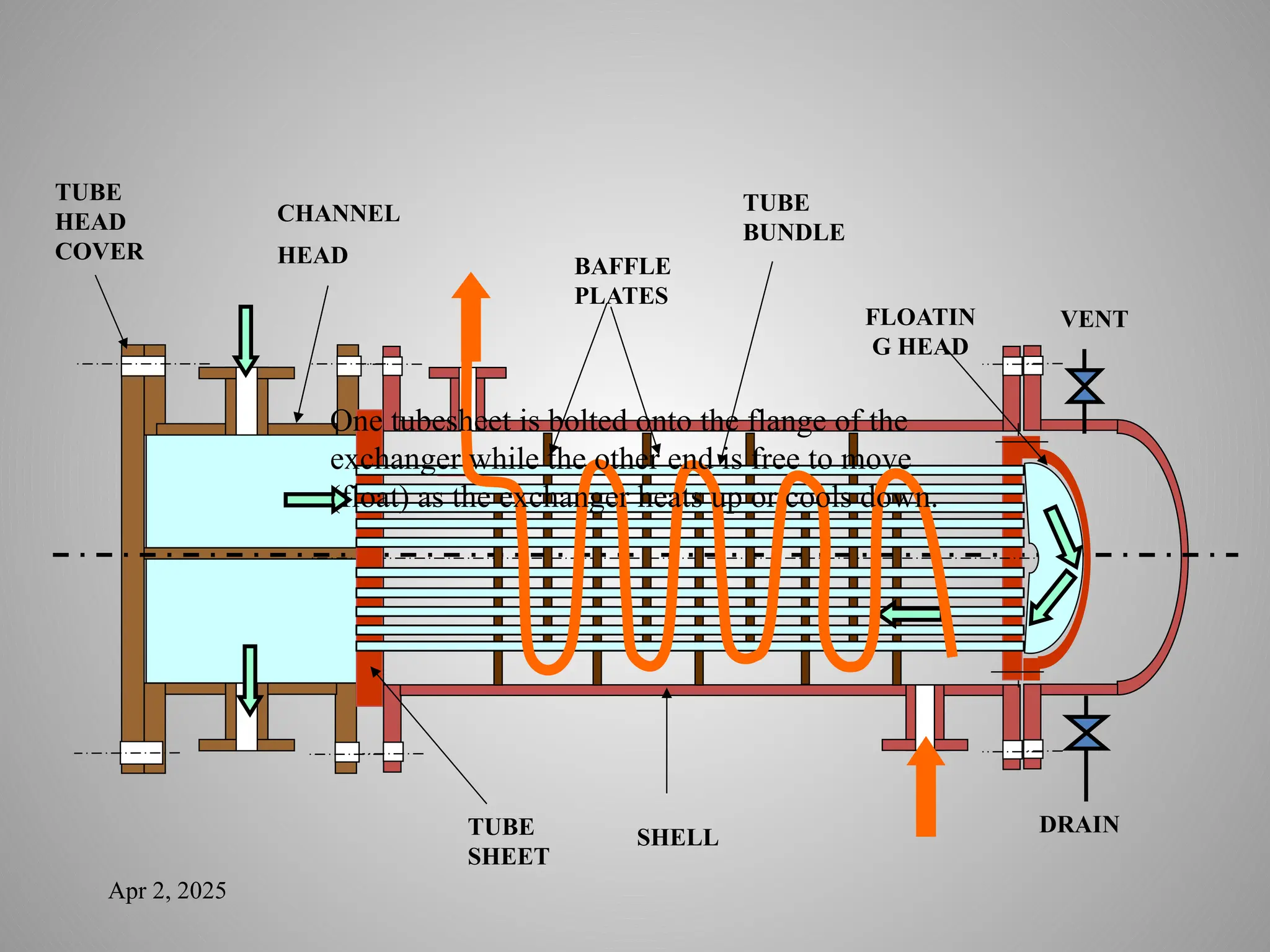
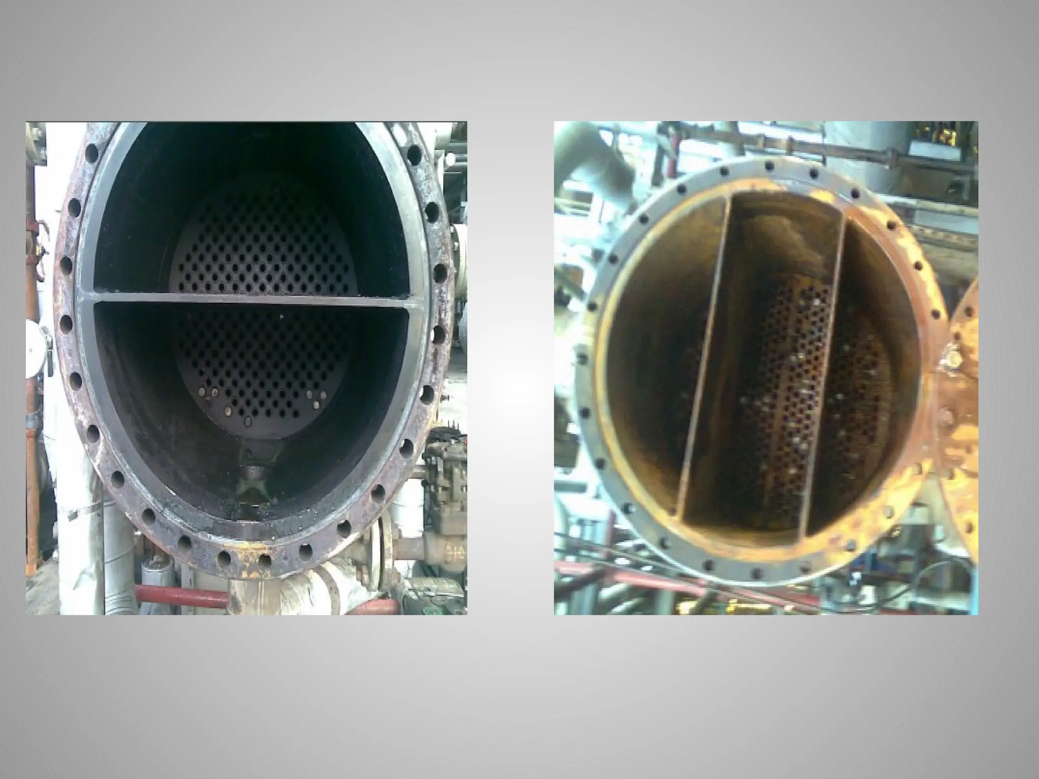
One tubesheet is bolted onto the flange of the
exchanger while the other end is free to move
(float) as the exchanger heats up or cools down.
38.
One tubesheet isbolted onto the flange of the exchanger while the
other end is free to move (float) as the exchanger heats up or cools
down.
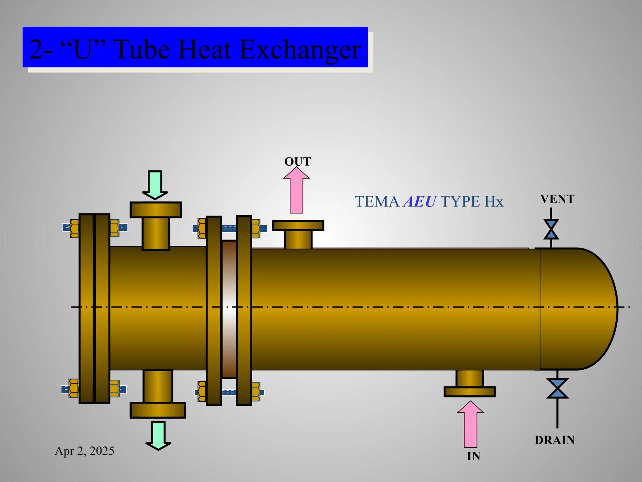
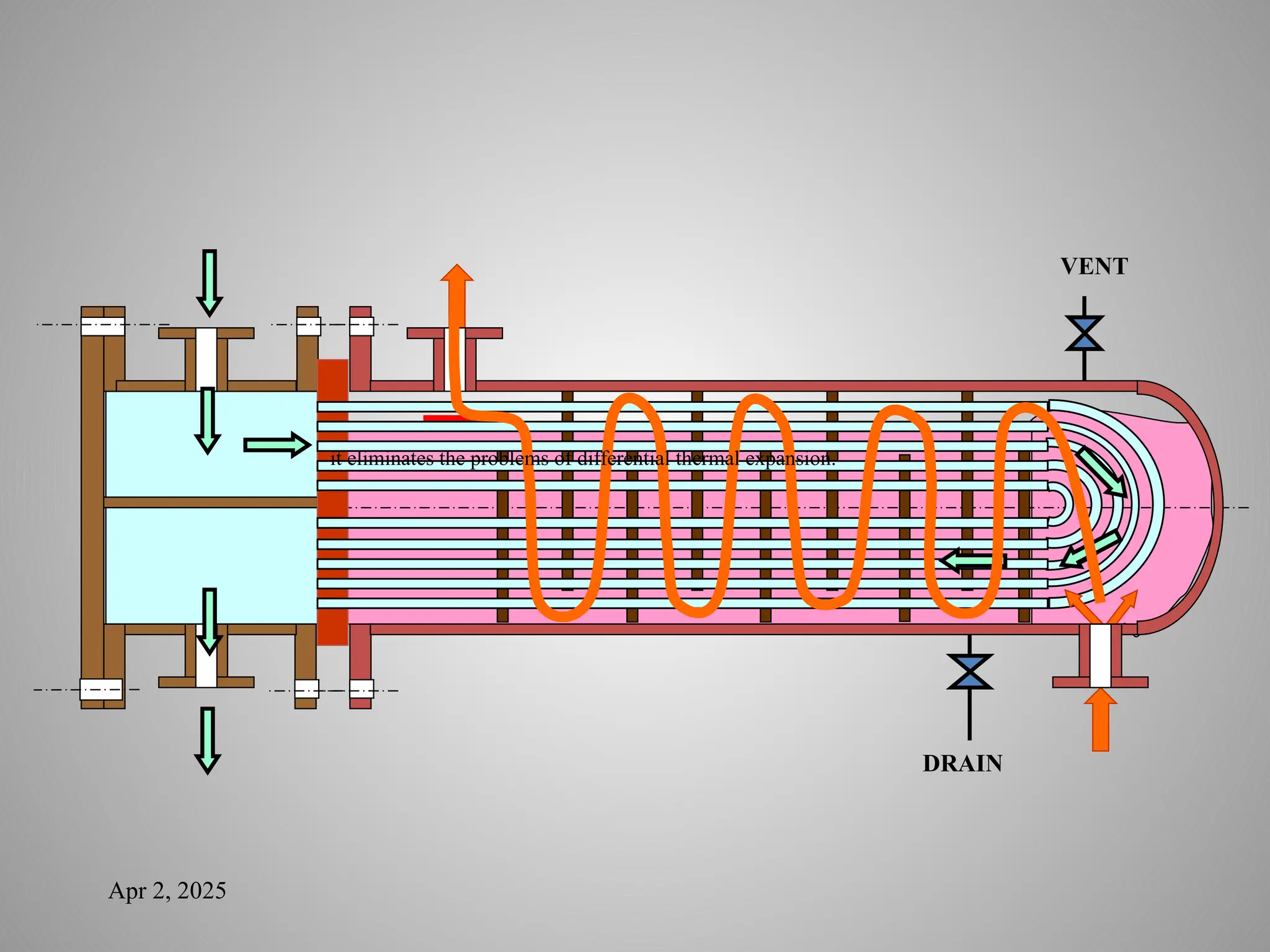
it eliminates theproblems of differential thermal expansion.
The tubesheet is bolted onto one flange at one end of the
exchanger, but the tubes are free to expand and contract as
necessary inside the shell.
The U-tube bundle can be easily removed for cleaning and
maintenance.
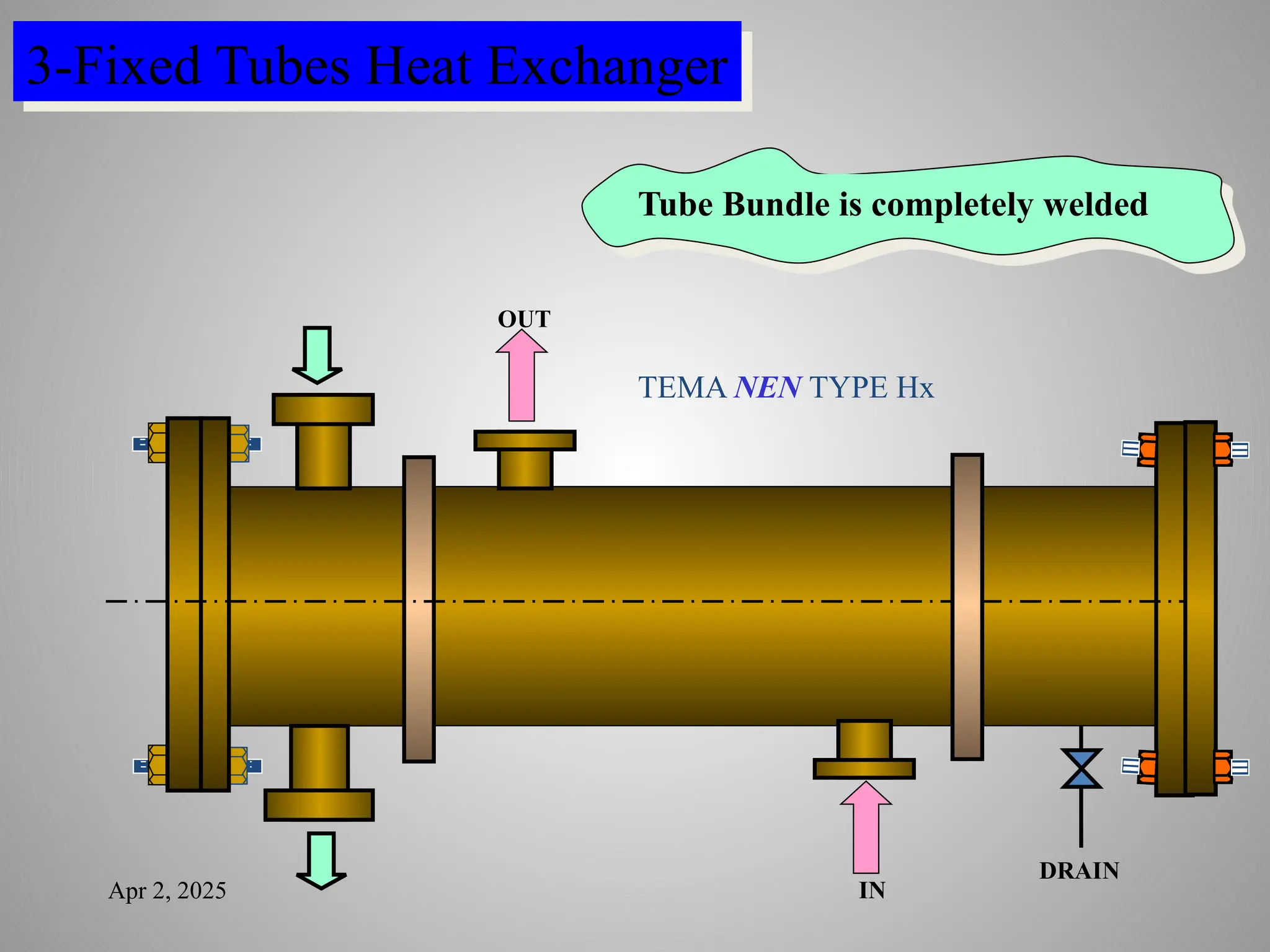
The fixed tubesheetshell and tube heat exchanger is simple in
design: and easy to fabricate, resulting in a lower initial capital
cost. Individual tubes can be easily repaired or plugged.
The main disadvantage is that the tube bundle cannot be
removed for cleaning, maintenance or inspection. Because of
this, the fixed tubesheet exchanger is best suited for service
where the shell side fluids are clean The inside of the tubes can
be accessed for cleaning and should be the side carrying the
dirtier fluid. Chemical cleaning is the only method of cleaning
the outside of the tubes.
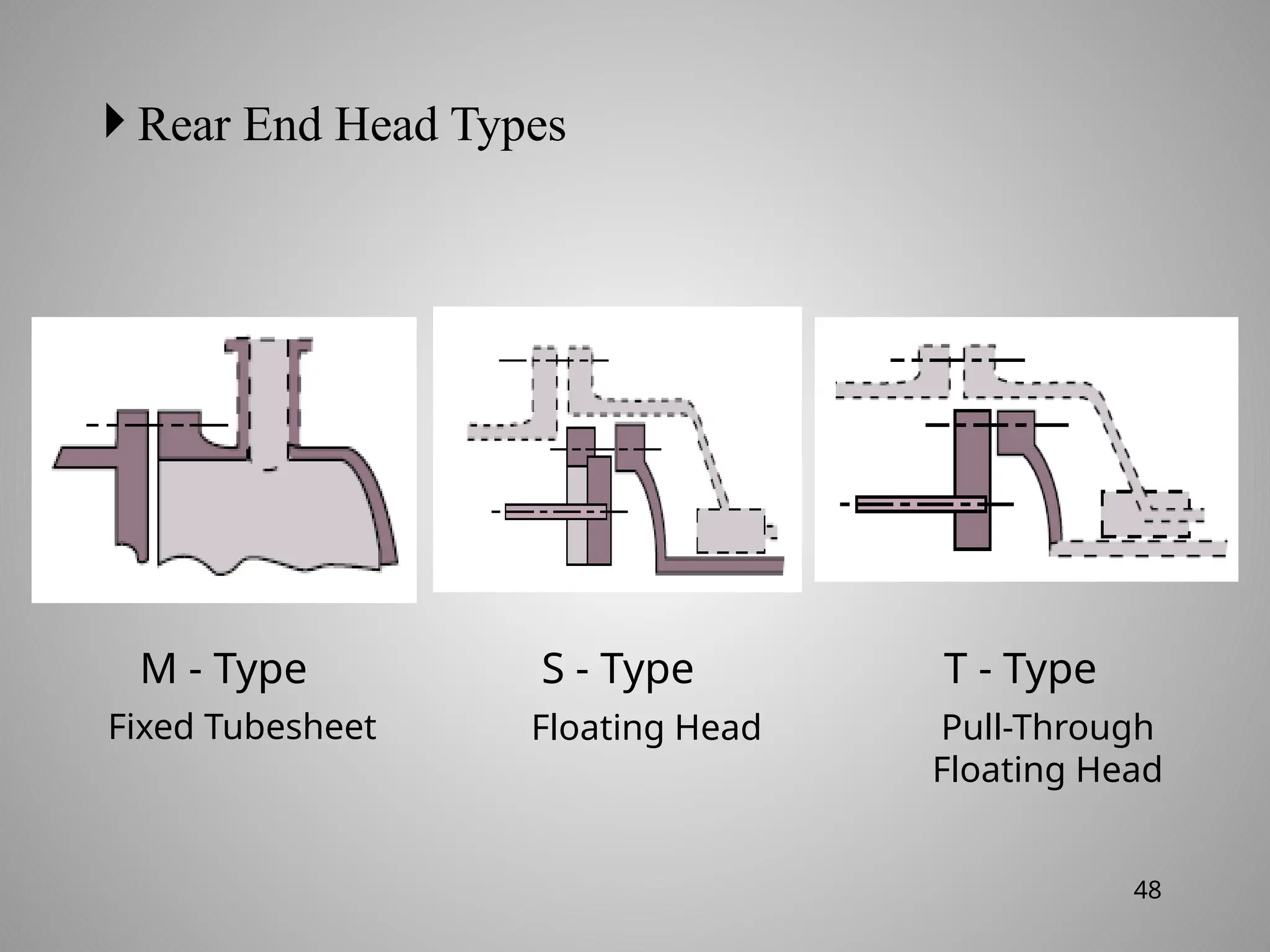
Rear EndHead Types
M - Type S - Type T - Type
Fixed Tubesheet Floating Head Pull-Through
Floating Head
48
49.
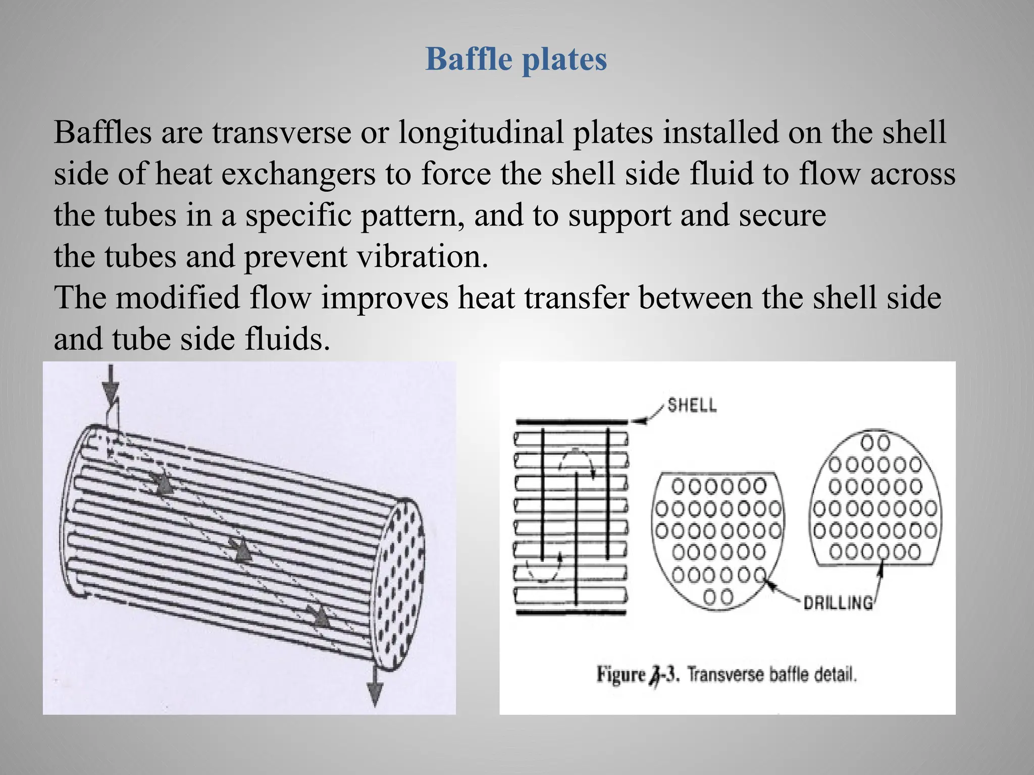
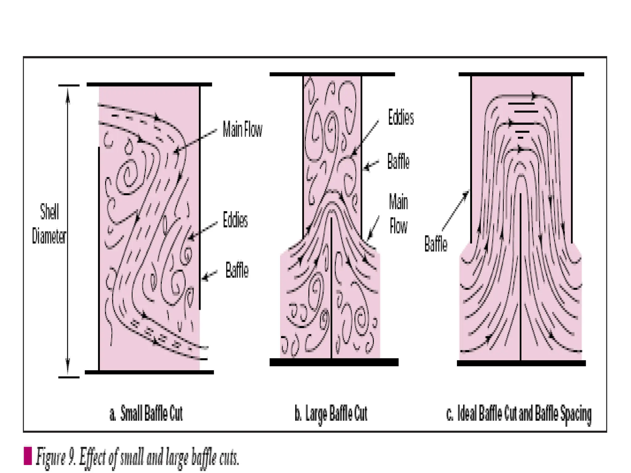
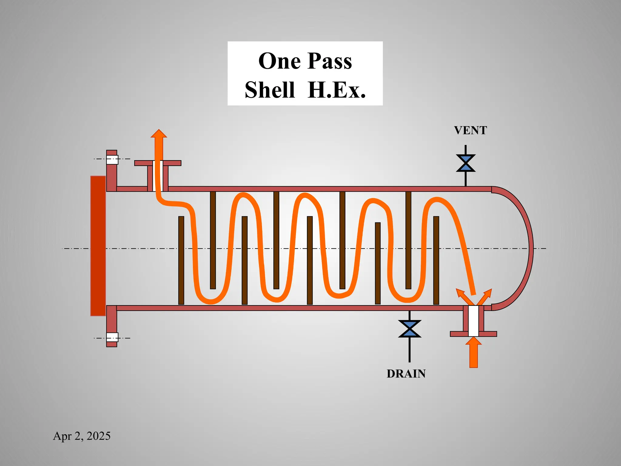
Baffle plates
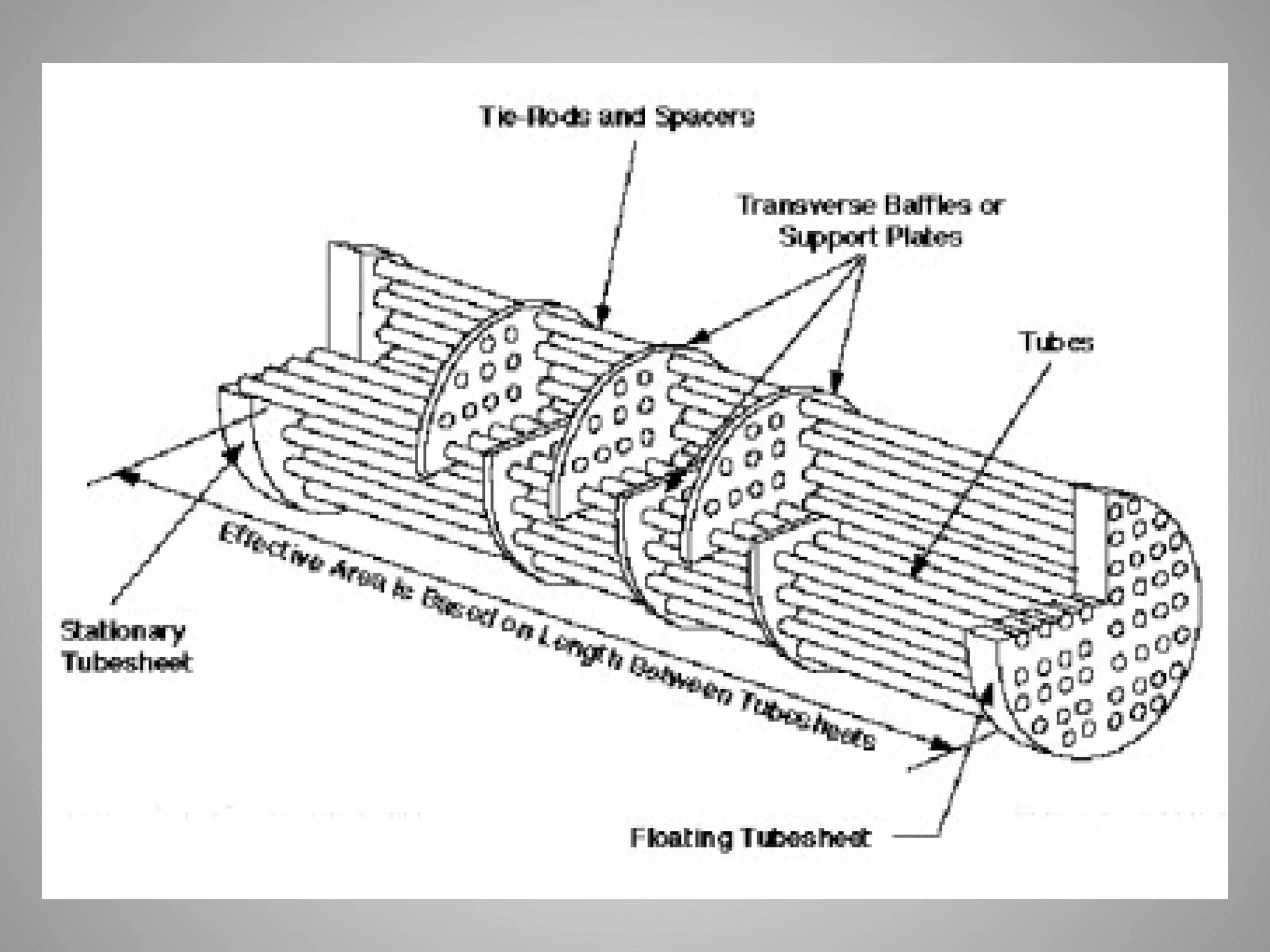
Baffles aretransverse or longitudinal plates installed on the shell
side of heat exchangers to force the shell side fluid to flow across
the tubes in a specific pattern, and to support and secure
the tubes and prevent vibration.
The modified flow improves heat transfer between the shell side
and tube side fluids.
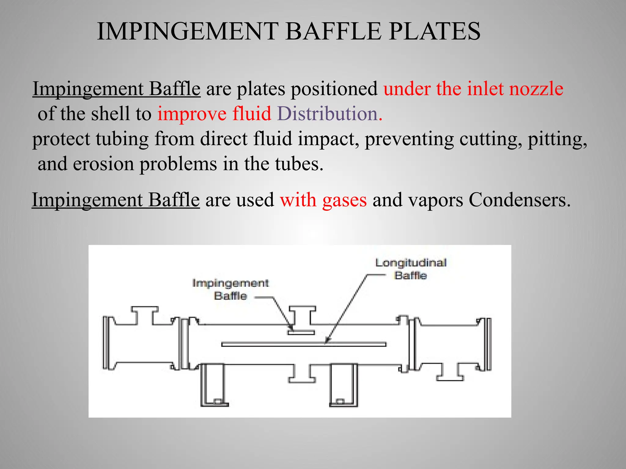
IMPINGEMENT BAFFLE PLATES
ImpingementBaffle are plates positioned under the inlet nozzle
of the shell to improve fluid Distribution.
protect tubing from direct fluid impact, preventing cutting, pitting,
and erosion problems in the tubes.
.
Impingement Baffle are used with gases and vapors Condensers.
54.
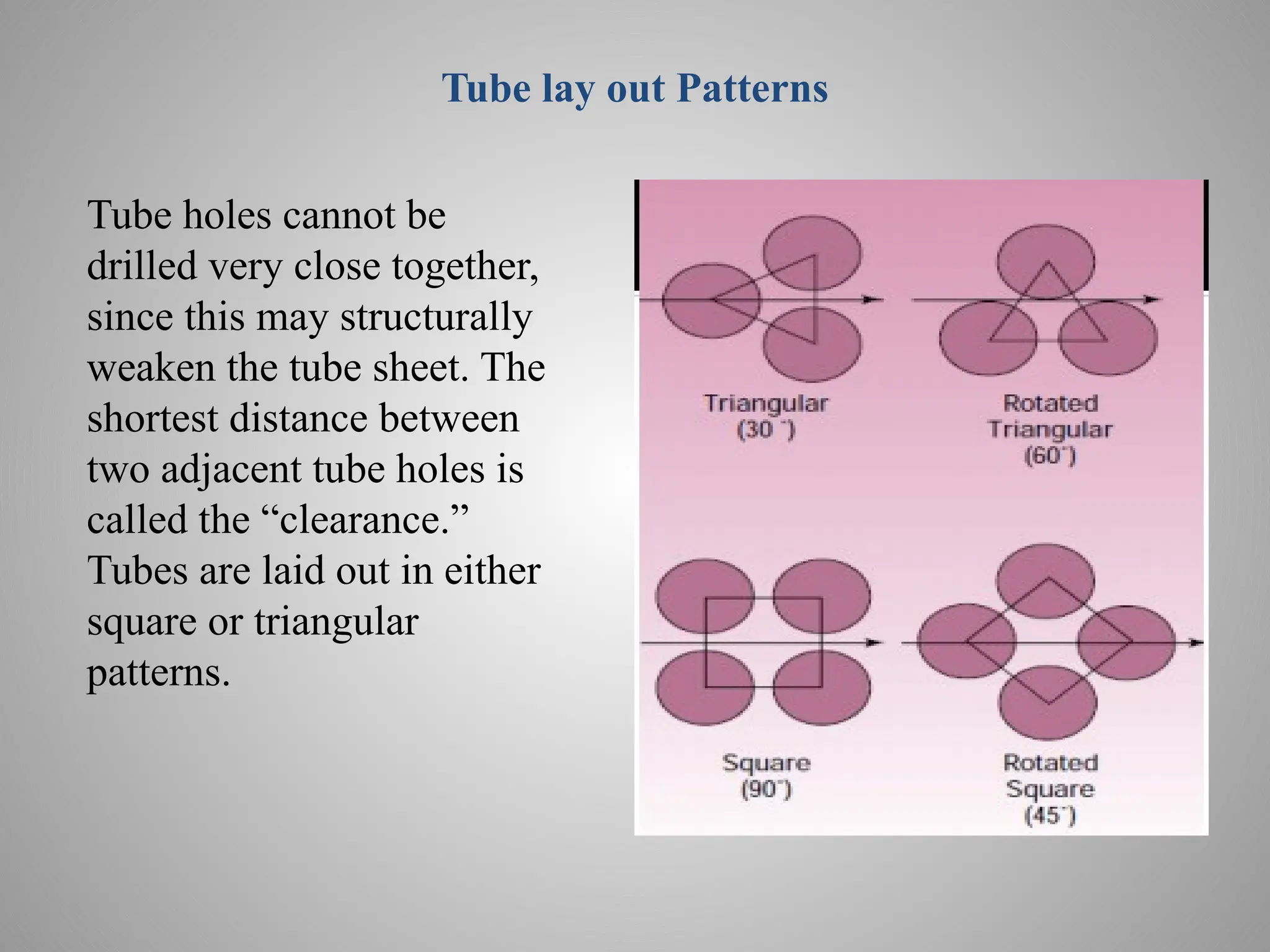
Tube lay outPatterns
Tube holes cannot be
drilled very close together,
since this may structurally
weaken the tube sheet. The
shortest distance between
two adjacent tube holes is
called the “clearance.”
Tubes are laid out in either
square or triangular
patterns.
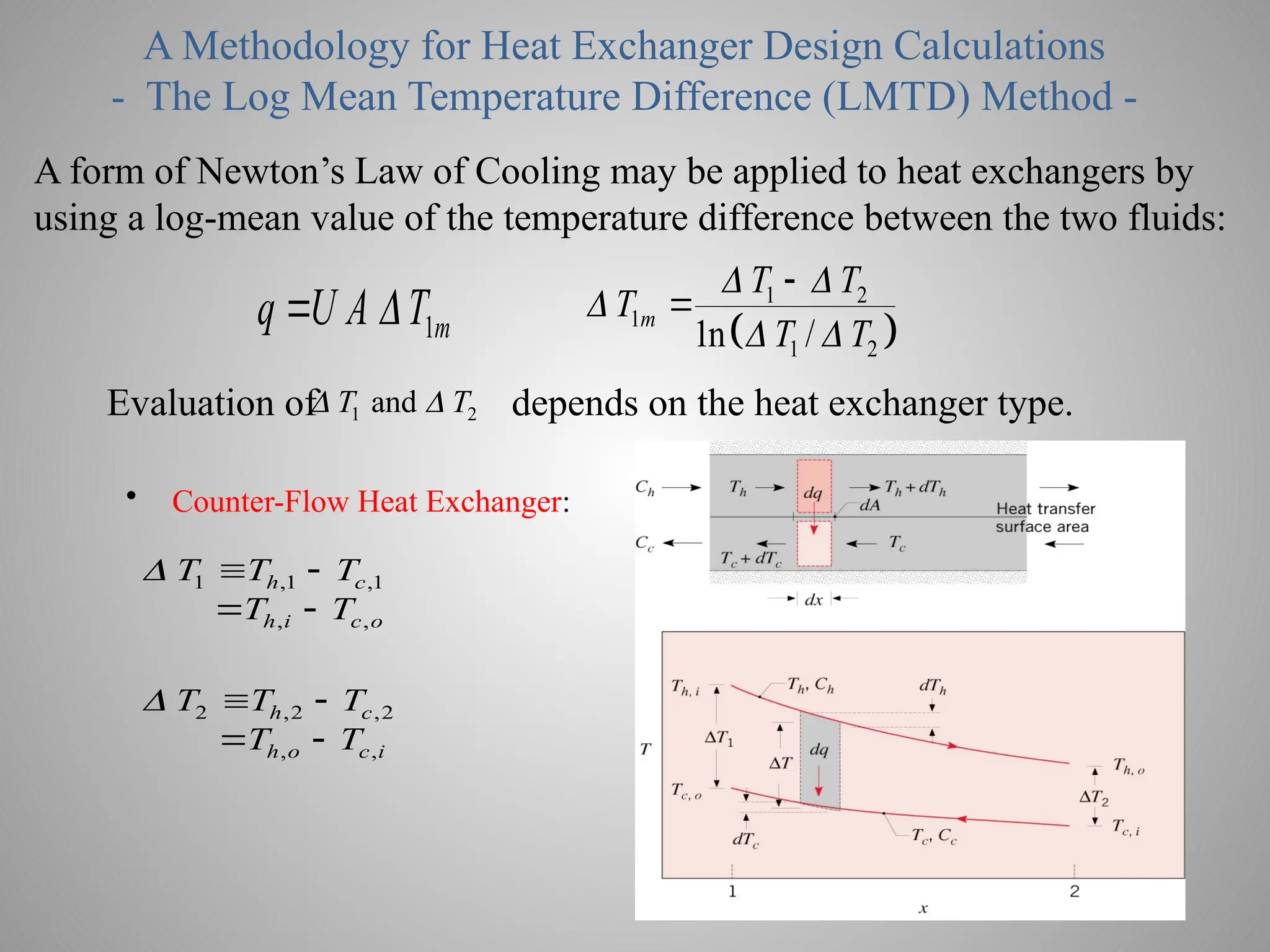
A Methodology forHeat Exchanger Design Calculations
- The Log Mean Temperature Difference (LMTD) Method -
A form of Newton’s Law of Cooling may be applied to heat exchangers by
using a log-mean value of the temperature difference between the two fluids:
1m
q U A T
1 2
1
1 2
1n /
m
T T
T
T T
Evaluation of depends on the heat exchanger type.
1 2
and
T T
• Counter-Flow Heat Exchanger:
1 ,1 ,1
, ,
h c
h i c o
T T T
T T
2 ,2 ,2
, ,
h c
h o c i
T T T
T T
63.
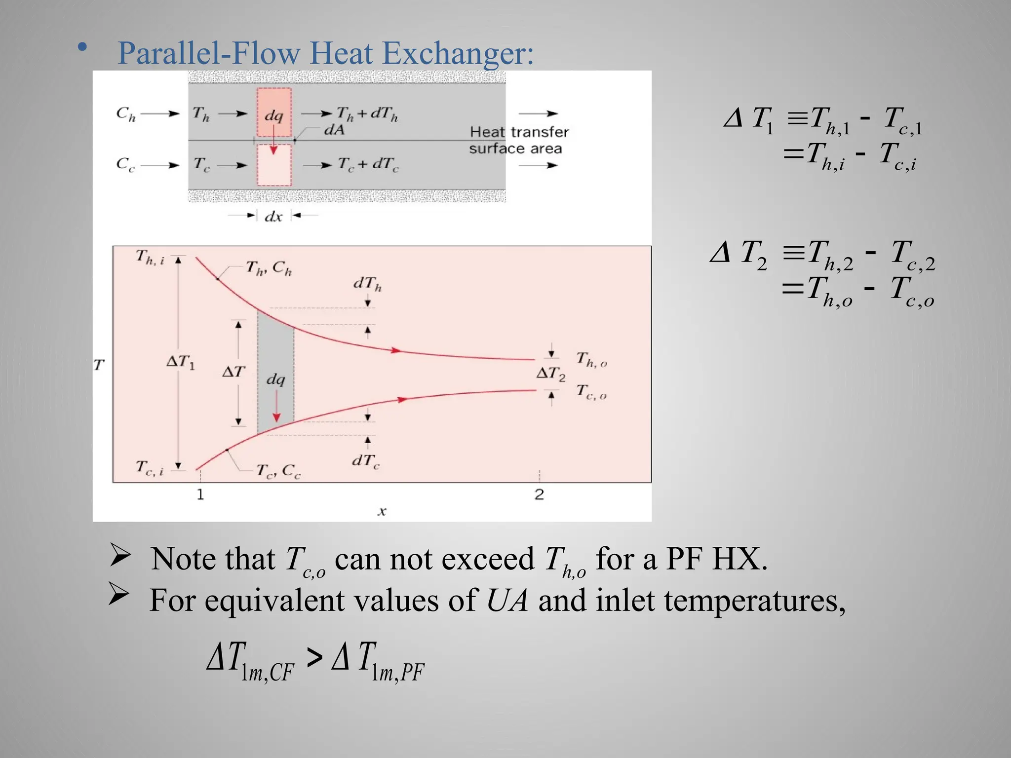
• Parallel-Flow HeatExchanger:
1 ,1 ,1
, ,
h c
h i c i
T T T
T T
2 ,2 ,2
, ,
h c
h o c o
T T T
T T
Note that Tc,o can not exceed Th,o for a PF HX.
For equivalent values of UA and inlet temperatures,
1 , 1 ,
m CF m PF
T T
64.
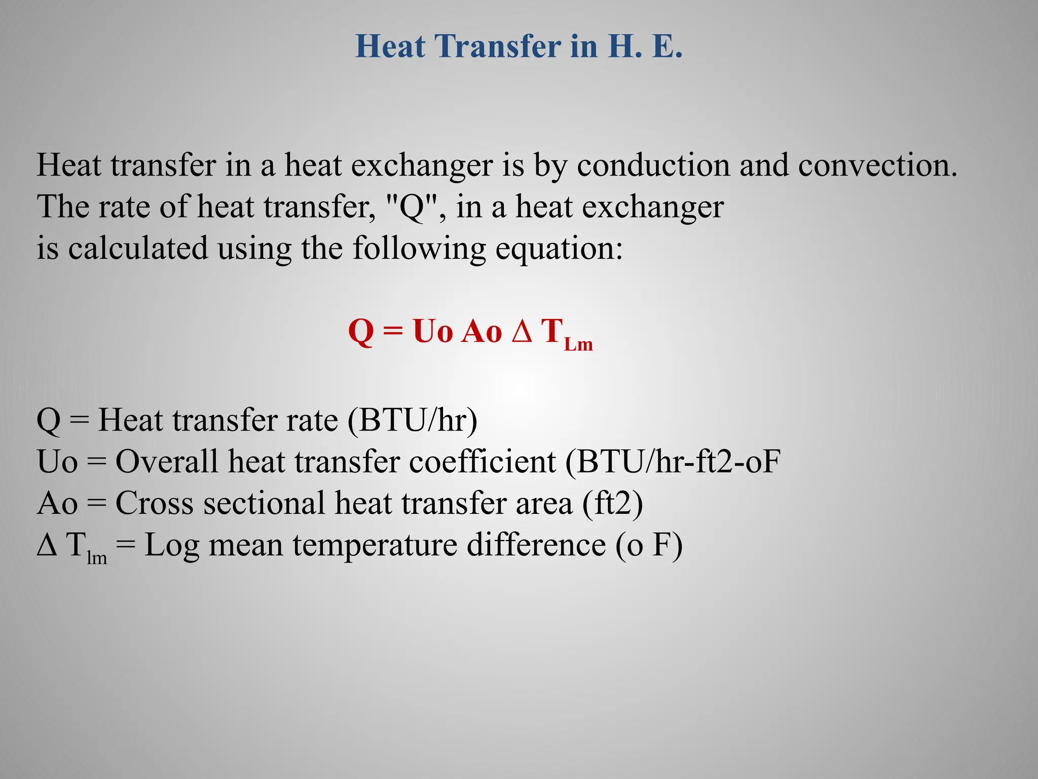
Heat Transfer inH. E.
Heat transfer in a heat exchanger is by conduction and convection.
The rate of heat transfer, "Q", in a heat exchanger
is calculated using the following equation:
Q = Uo Ao ∆ TLm
Q = Heat transfer rate (BTU/hr)
Uo = Overall heat transfer coefficient (BTU/hr-ft2-oF
Ao = Cross sectional heat transfer area (ft2)
∆ Tlm = Log mean temperature difference (o F)
65.
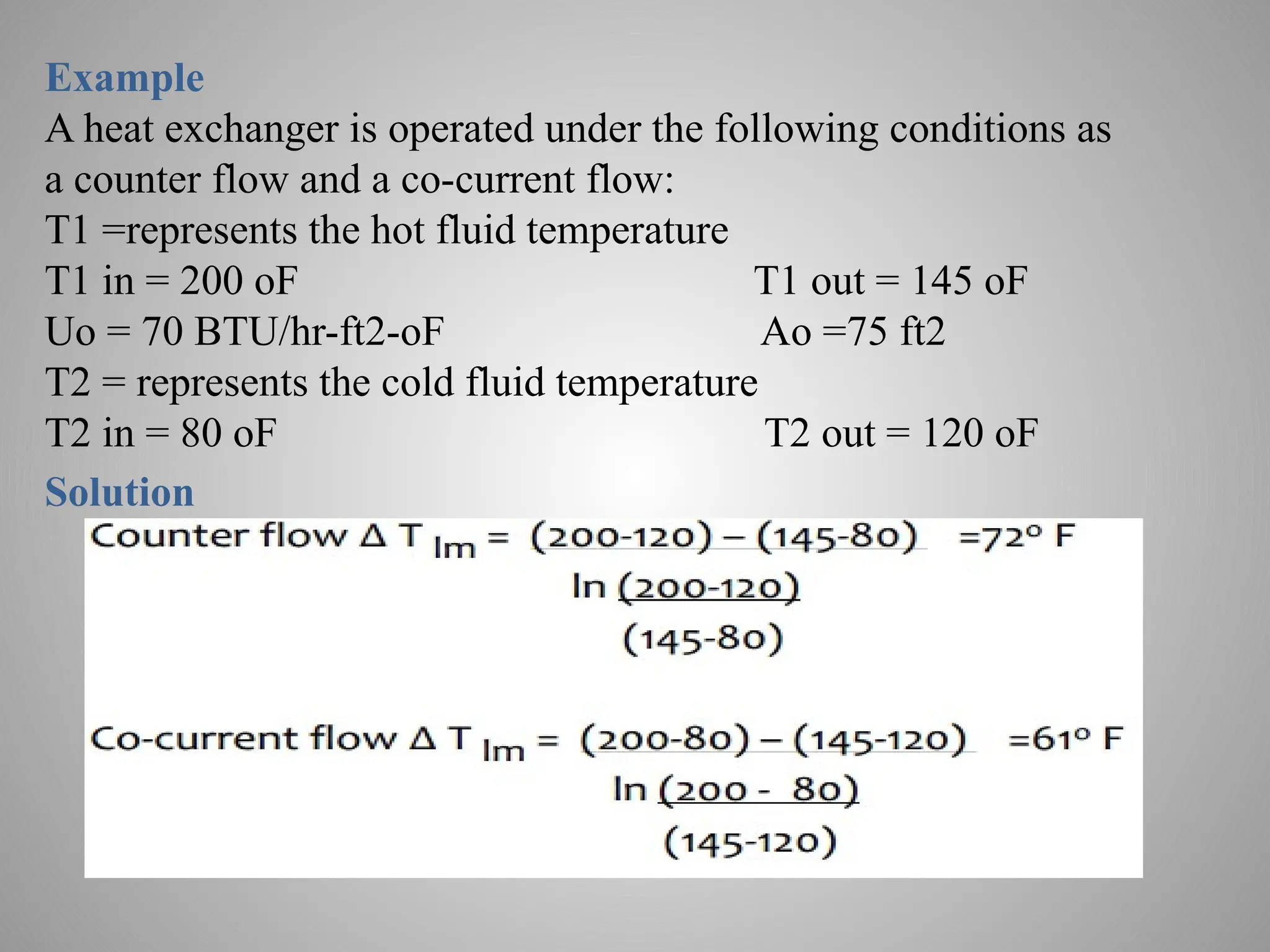
Example
A heat exchangeris operated under the following conditions as
a counter flow and a co-current flow:
T1 =represents the hot fluid temperature
T1 in = 200 oF T1 out = 145 oF
Uo = 70 BTU/hr-ft2-oF Ao =75 ft2
T2 = represents the cold fluid temperature
T2 in = 80 oF T2 out = 120 oF
Solution
66.
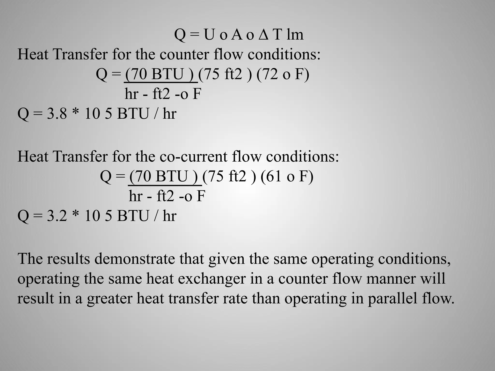
Q = Uo A o ∆ T lm
Heat Transfer for the counter flow conditions:
Q = (70 BTU ) (75 ft2 ) (72 o F)
hr - ft2 -o F
Q = 3.8 * 10 5 BTU / hr
Heat Transfer for the co-current flow conditions:
Q = (70 BTU ) (75 ft2 ) (61 o F)
hr - ft2 -o F
Q = 3.2 * 10 5 BTU / hr
The results demonstrate that given the same operating conditions,
operating the same heat exchanger in a counter flow manner will
result in a greater heat transfer rate than operating in parallel flow.
67.
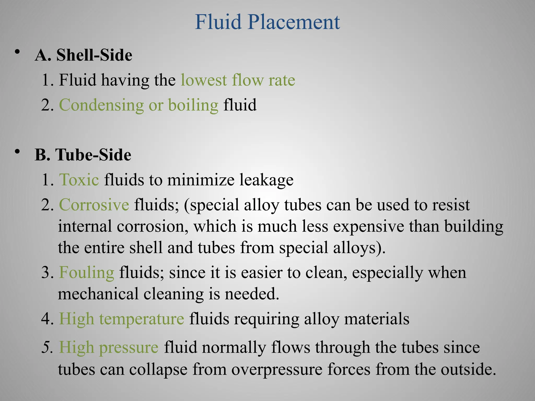
Fluid Placement
• A.Shell-Side
1. Fluid having the lowest flow rate
2. Condensing or boiling fluid
• B. Tube-Side
1. Toxic fluids to minimize leakage
2. Corrosive fluids; (special alloy tubes can be used to resist
internal corrosion, which is much less expensive than building
the entire shell and tubes from special alloys).
3. Fouling fluids; since it is easier to clean, especially when
mechanical cleaning is needed.
4. High temperature fluids requiring alloy materials
5. High pressure fluid normally flows through the tubes since
tubes can collapse from overpressure forces from the outside.
68.
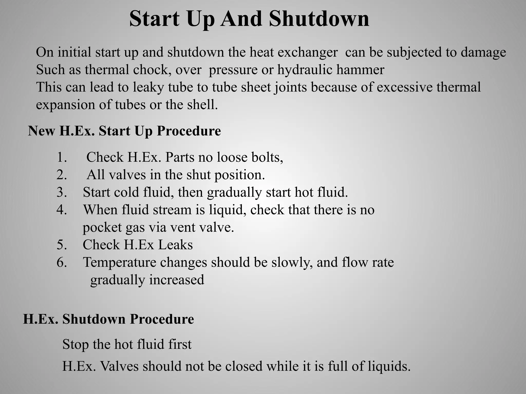
Start Up AndShutdown
On initial start up and shutdown the heat exchanger can be subjected to damage
Such as thermal chock, over pressure or hydraulic hammer
This can lead to leaky tube to tube sheet joints because of excessive thermal
expansion of tubes or the shell.
New H.Ex. Start Up Procedure
1. Check H.Ex. Parts no loose bolts,
2. All valves in the shut position.
3. Start cold fluid, then gradually start hot fluid.
4. When fluid stream is liquid, check that there is no
pocket gas via vent valve.
5. Check H.Ex Leaks
6. Temperature changes should be slowly, and flow rate
gradually increased
H.Ex. Shutdown Procedure
H.Ex. Valves should not be closed while it is full of liquids.
Stop the hot fluid first
69.
How to detectOperational Problem
Decline of heat transfer efficiency
High pressure drop
Internal gasket leaks
External leaks
Laboratory Sample results
Internal Tubes leaks
70.
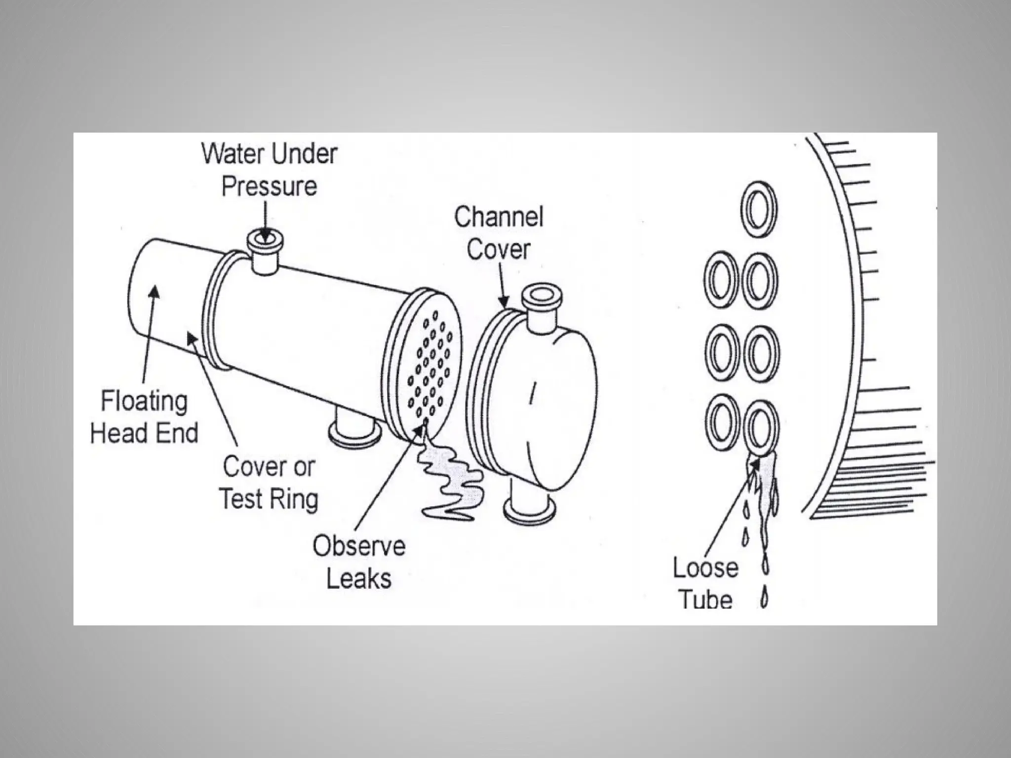
1- Tubes Leaking
2-Tube Sheet Leaking
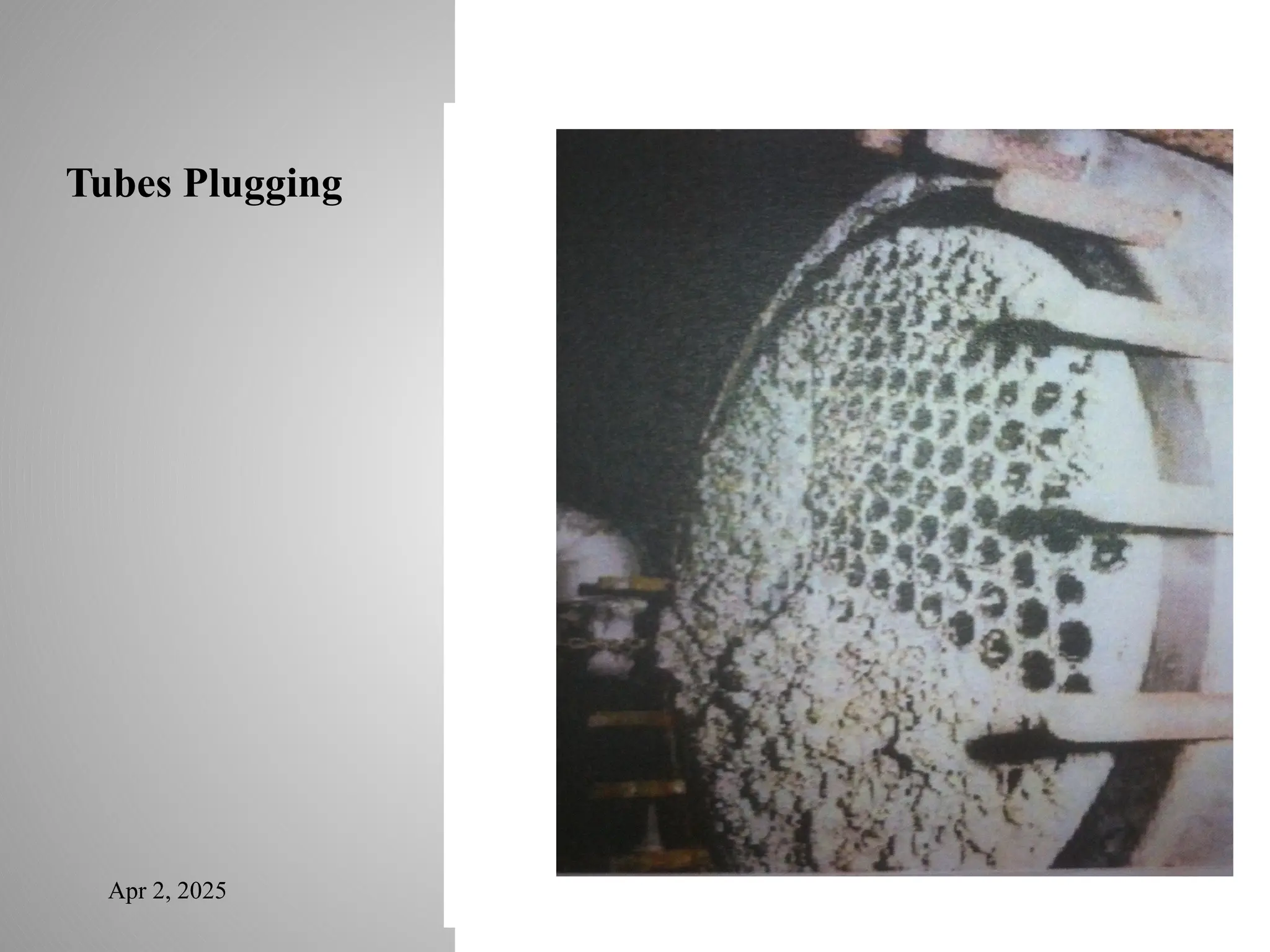
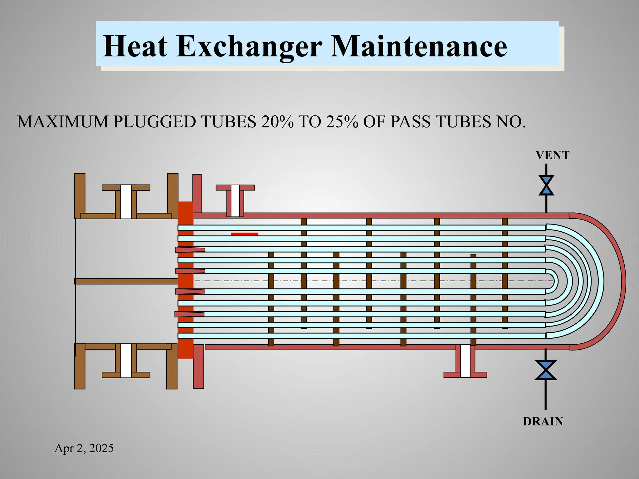
3- Tubes Plugging
4- Shell Plugging
H.Ex. Leak Test
Hydrostatic Test
Sample Lab. Test
Visual Leak Test
Types Of H.Ex. Failure
Apr 2, 2025
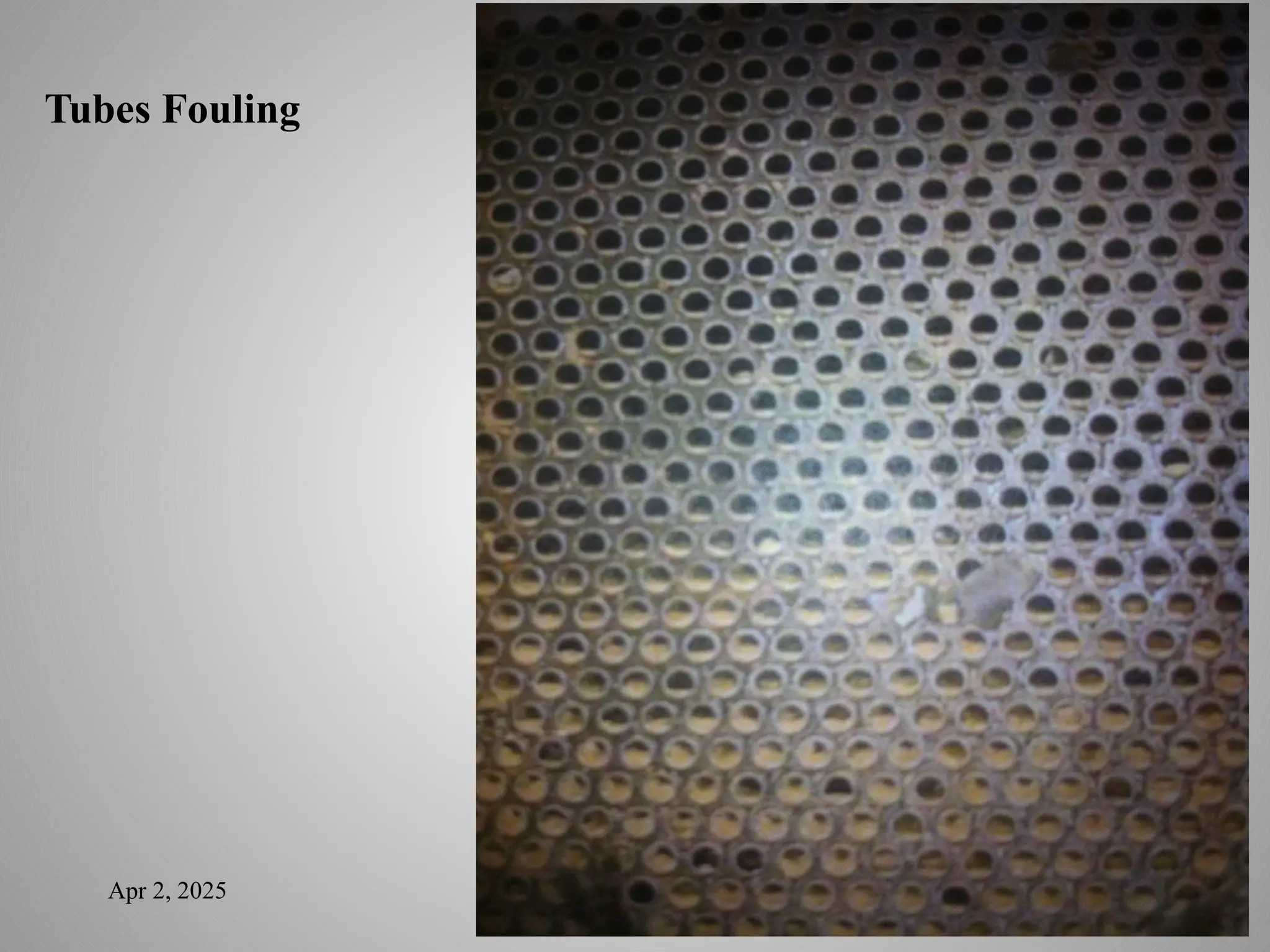
HeatEx. Fouling
Fouling definition
Fouling is a trim used to describe undesirable deposits on a heat
exchanger surface. These deposits result in an increase of resistance
to both fluid flow and heat transfer. A slight sludge or scale buildup
on either side of the tube greatly reduces effectiveness. An increase
in pressure drop through the exchanger or a drop in heat exchange
efficiency usually indicates that cleaning is needed.
Types of Fouling
Mineral scales,
Sedimentation (dirt or clay in the cooling water supply),
ƒ
Coking (hot surfaces and carbon deposits),
ƒ
Corrosion
ƒ
75.
How to handlethe problem of Fouling
• Mineral scales can be combated with chemical treatments while
the process is running.
• Sedimentation is prevented or lessened through the proper use of
a filtering system.
• Corrosion is prevented through the proper selection of exchanger
materials as well as through use of corrosion inhibitor.
• Coking is common in hydrocarbon processing and is not always
possible to eliminate.
• Hydro blasting cleaning (high pressure water jet pump) 10,000
psi
For out side tube fouling and Shell cleaning
Turbine cleaning for inside tube heavy fouling and Shell cleaning
76.
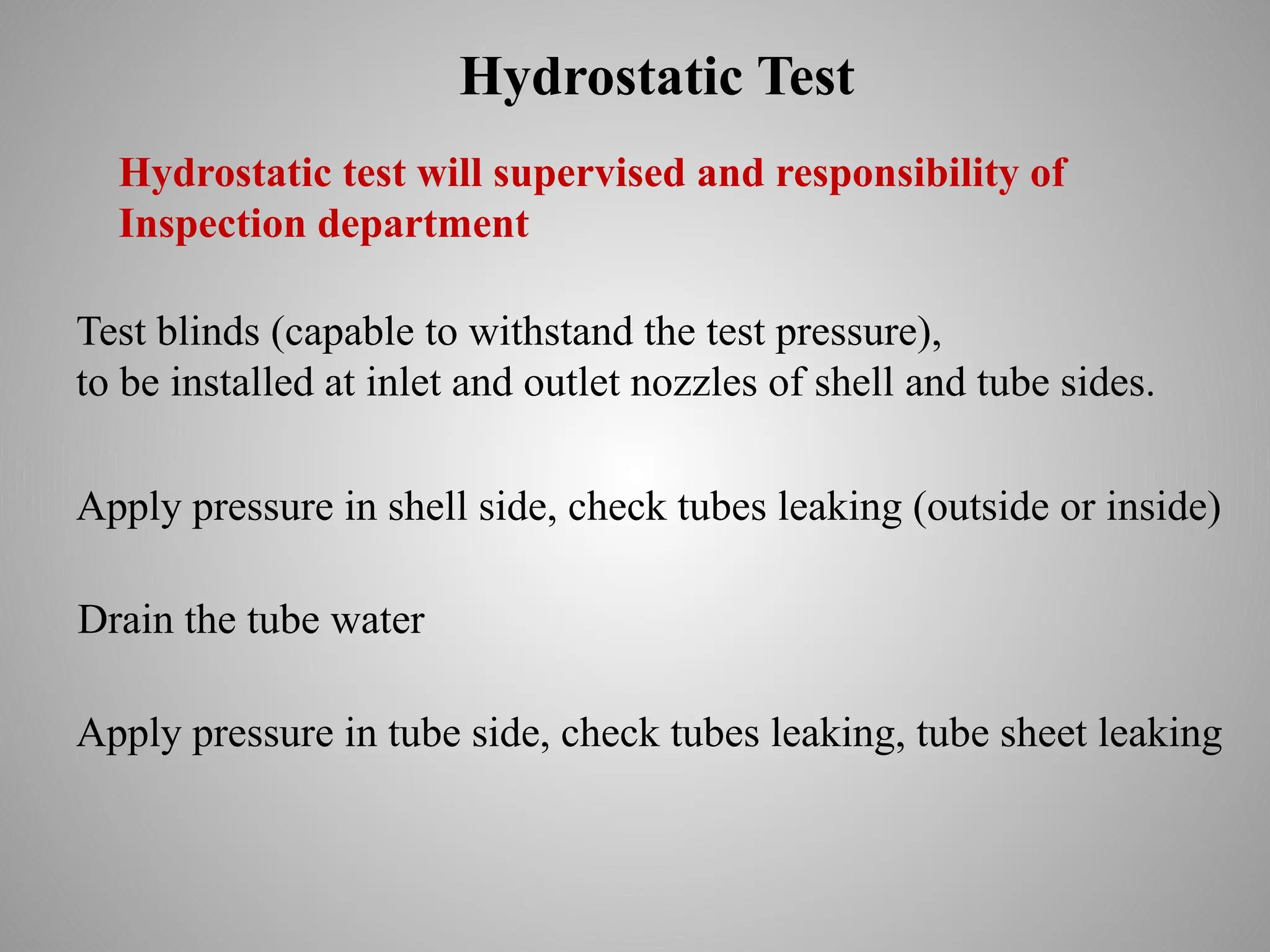
Hydrostatic Test
Test blinds(capable to withstand the test pressure),
to be installed at inlet and outlet nozzles of shell and tube sides.
Apply pressure in shell side, check tubes leaking (outside or inside)
Hydrostatic test will supervised and responsibility of
Inspection department
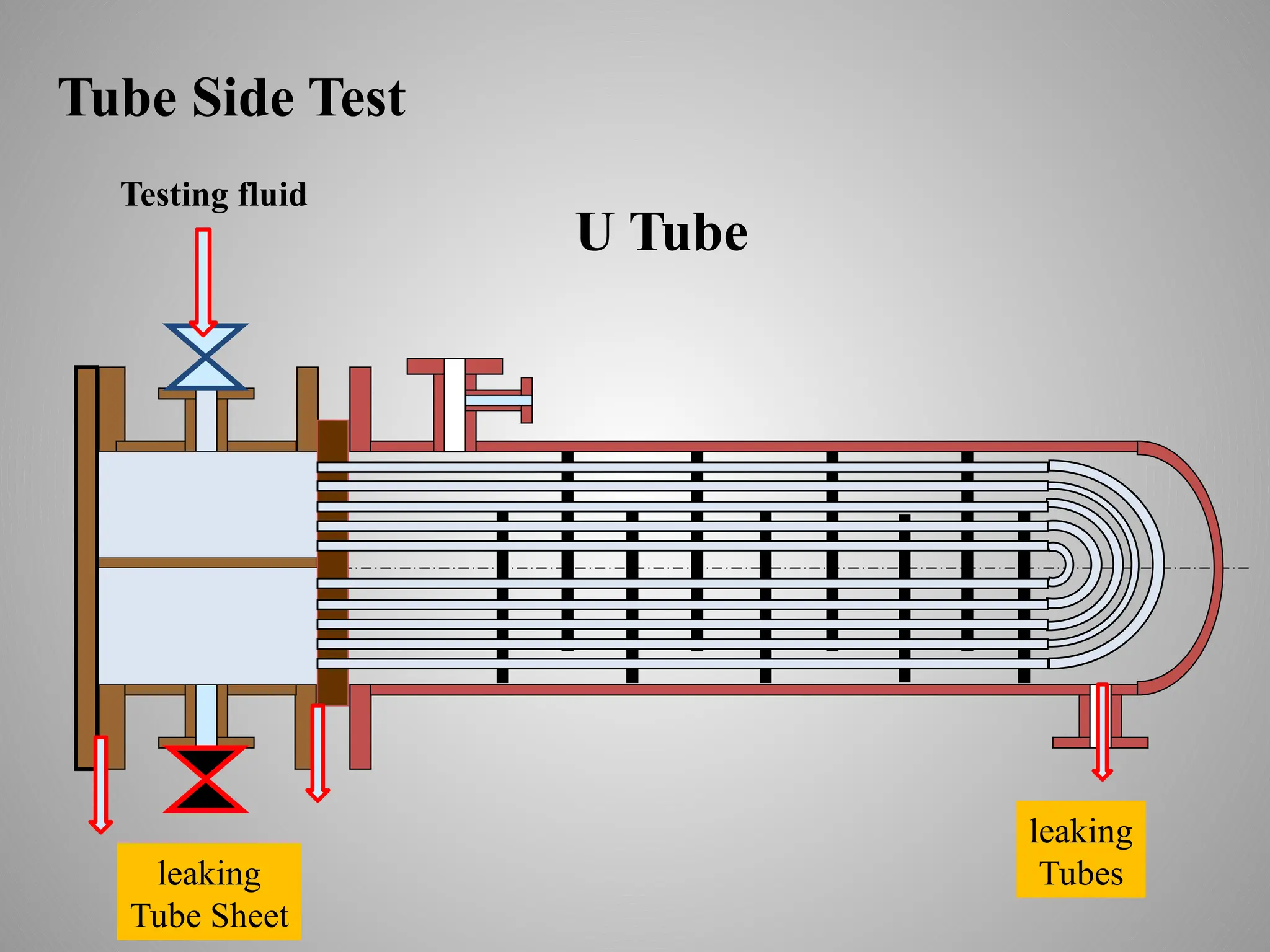
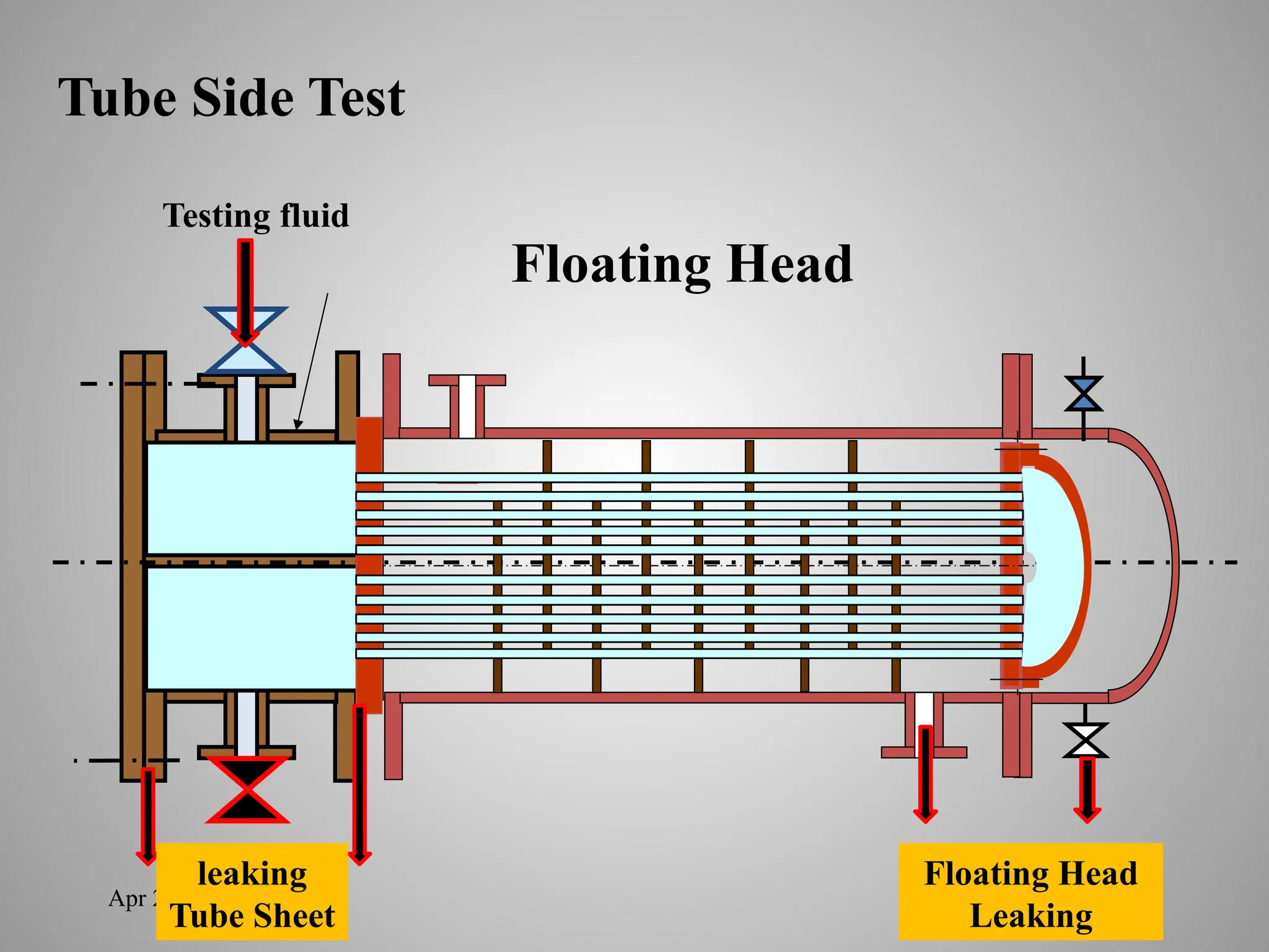
Apply pressure in tube side, check tubes leaking, tube sheet leaking
Drain the tube water
77.
Apr 2, 2025
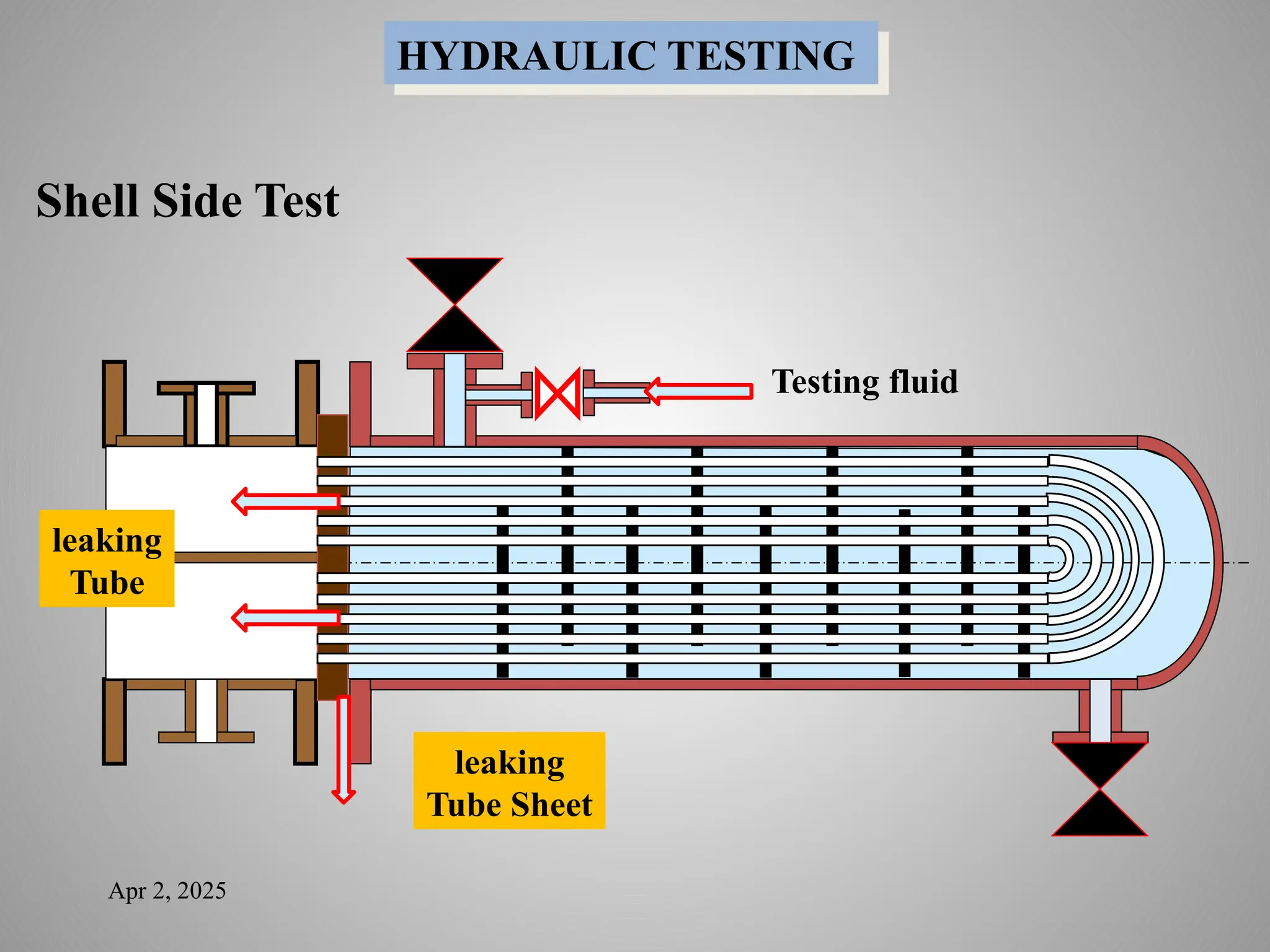
HYDRAULICTESTING
Testing fluid
leaking
Tube
leaking
Tube Sheet
Shell Side Test