Downloaded 292 times
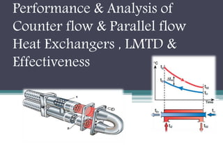
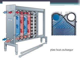
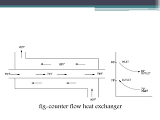
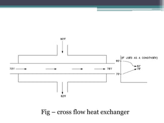
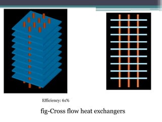
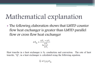
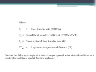
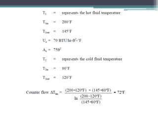
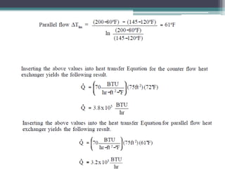

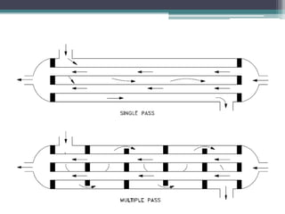
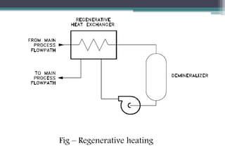
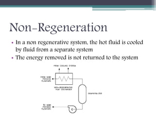


This document discusses different types of heat exchangers, including tube and shell and plate heat exchangers. It describes parallel flow, counter flow, and cross flow configurations. Counter flow heat exchangers are most efficient due to having the highest log mean temperature difference. The effectiveness-NTU method is introduced to calculate heat transfer rate when inlet/outlet temperatures are unknown. Heat exchangers are also classified as regenerative or non-regenerative based on whether the same fluid acts as both the heated and cooled fluid.


