Downloaded 712 times


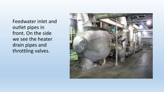

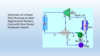


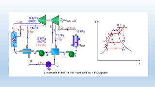


This document describes closed feedwater heaters used in power plants. It discusses: - Closed feedwater heaters are shell and tube heat exchangers that preheat boiler feedwater using extracted steam, improving cycle efficiency. No separate pumps are needed since streams remain at the same pressure. - Advantages include reduced irreversibility in steam generation and avoiding thermal shock to boiler metal. - Most power plants use a combination of open and closed feedwater heaters due to complexity and cost of closed heaters.


