Downloaded 657 times


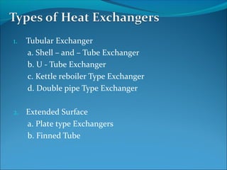


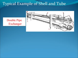
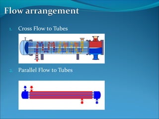

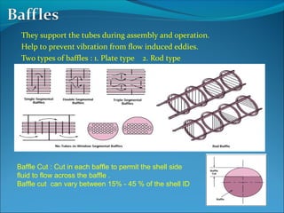


A heat exchanger transfers heat between two fluids through tube walls. There are two main types: tubular and extended surface. Tubular exchangers include shell-and-tube, U-tube, and double pipe designs. Shell-and-tube exchangers contain tubes in a shell separated by baffles to direct flow. Heat is transferred through the tube walls from one fluid inside the tubes to the other outside. Manufacturing involves forming, welding, inspection, assembly, testing, and documentation. Materials, design, fabrication, and testing must meet codes and standards.


