Download to read offline

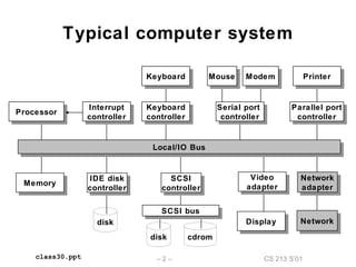
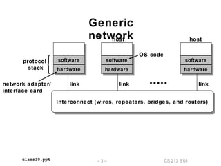
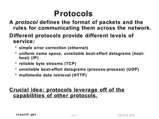
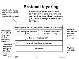
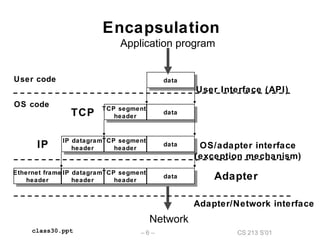
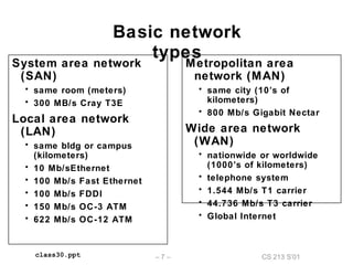
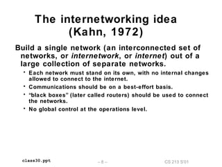
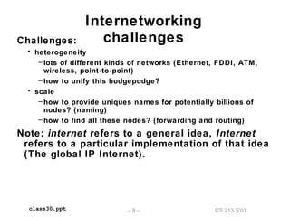
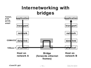
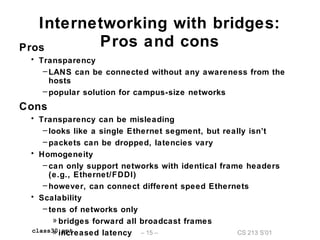
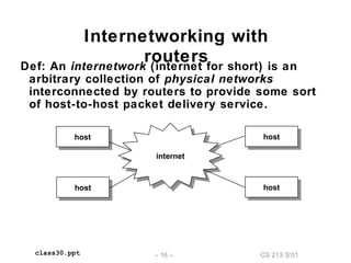
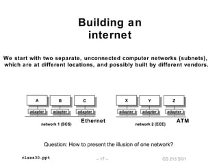
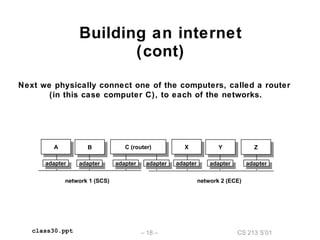
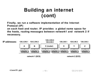
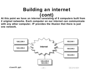
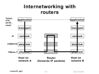
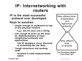
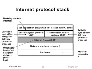
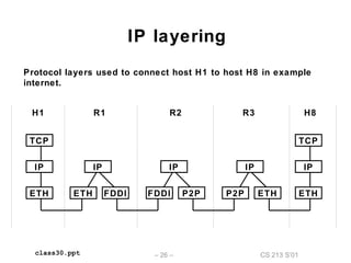
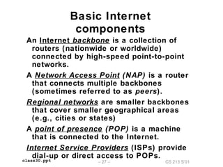
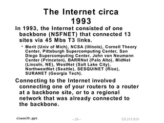
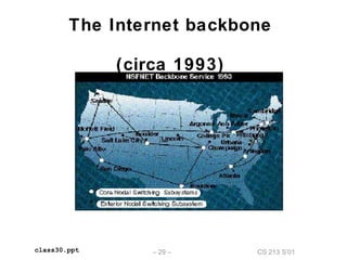


The document outlines the principles of internetworking, discussing protocol layering, encapsulation, and types of networks. It explains how various protocols, like IP and TCP, work together to support communication across different network types. Additionally, it describes the architecture of the internet, including components such as routers and network access points, and addresses the challenges of heterogeneity and scalability in network connections.

![ppt on IC [Integrated Circuit]](https://cdn.slidesharecdn.com/ss_thumbnails/1-171227170055-thumbnail.jpg?width=640&height=640&fit=bounds)