Download to read offline

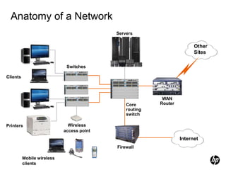
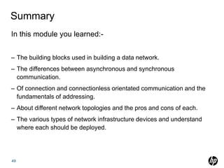


This document provides an overview of networking fundamentals and concepts. It outlines topics like basic communication concepts involving data, voice and video transfer. It describes networking hardware components like hubs, switches, routers and wireless access points. It also explains networking protocols like Ethernet, VLANs, OSI model layers and network topologies including LAN, WAN and wireless networks. The learning objectives are to understand building blocks of networks, data transmission, network devices and protocols.