Downloaded 100 times


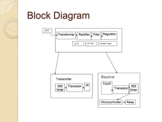


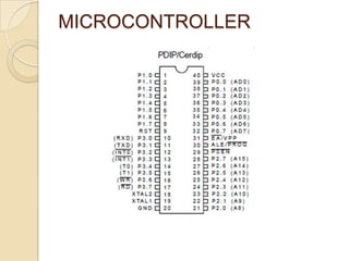


This document describes an automatic Mall elevator control system that uses an infrared sensor and microcontroller to automatically turn the elevator lights on when someone enters and off when they leave to save power. It includes block diagrams of the system components, detailed circuit diagrams and explanations of the infrared transmitter, receiver, microcontroller, and power supply circuits. The system aims to save electrical power by automatically controlling the elevator lights based on occupancy.


