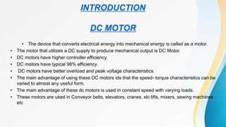
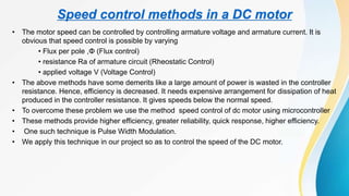
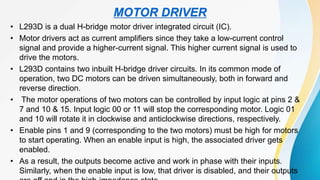
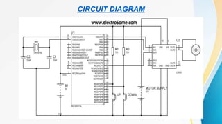
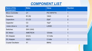
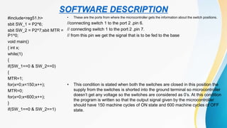
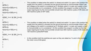
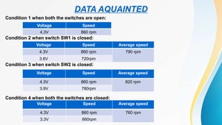
SPEED CONTROL OF DC MOTOR
USING
MICROCONTROLLER
CONTENTS
CHAPTER No. TITLE
1.
INTRODUCTION
1.1 DC Motor
1.2 Microcontroller
1.3 Motor Driver
2. CIRCUIT
DIAGRAM
3.
COMPONENTS LISTING
4. SOFTWARE
DESCRIPTION
5. DATA
ACQUAINTED
6. CONCLUSION
7. REFERENCES
INTRODUCTION
DC MOTOR
• The device that converts electrical energy into mechanical energy is called as a motor.
• The motor that utilizes a DC supply to produce mechanical output is DC Motor.
• DC motors have higher controller efficiency.
• DC motors have typical 98% efficiency.
• DC motors have better overload and peak voltage characteristics.
• The main advantage of using these DC motors ids that the speed- torque characteristics can be
varied to almost any useful form.
• The main advantage of these dc motors is used in constant speed with varying loads.
• These motors are used in Conveyor belts, elevators, cranes, ski lifts, mixers, sewing machines
etc
Speed control methods in a DC motor
• The motor speed can be controlled by controlling armature voltage and armature current. It is
obvious that speed control is possible by varying
• Flux per pole ,Φ (Flux control)
• resistance Ra of armature circuit (Rheostatic Control)
• applied voltage V (Voltage Control)
• The above methods have some demerits like a large amount of power is wasted in the controller
resistance. Hence, efficiency is decreased. It needs expensive arrangement for dissipation of heat
produced in the controller resistance. It gives speeds below the normal speed.
• To overcome these problem we use the method speed control of dc motor using microcontroller
• These methods provide higher efficiency, greater reliability, quick response, higher efficiency.
• One such technique is Pulse Width Modulation.
• We apply this technique in our project so as to control the speed of the DC motor.
• A microcontroller (abbreviated µC,uC or MUC)is a small computer on a single integrated circuit
containing a processor core, memory, and programmable input /output peripherals.
• This programmes memory in the form of NOR flash or OTP ROM is also often included on chip,as
well as typically small amount of RAM.
MICROCONTROLLER
PIC16F887A MICROCONTROLLER
• The PIC microcontroller PIC16f877a is one of the most renowned microcontrollers in the industry.
• This controller is very convenient to use, the coding or programming of this controller is also
easier.
• One of the main advantages is that it can be write-erase as many times as possible because it
use FLASH memory technology.
• It has a total number of 40 pins and there are 33 pins for input and output. PIC16F877A is used in
many pic microcontroller projects.
• PIC16F877A also have many application in digital electronics circuits.
• PIC16f877a finds its applications in a huge number of devices.
• It is used in remote sensors, security and safety devices, home automation and in many industrial
instruments.
• An EEPROM is also featured in it which makes it possible to store some of the information permanently
like transmitter codes and receiver frequencies and some other related data.
• The cost of this controller is low and its handling is also easy. Its flexible and can be used in areas where
microcontrollers have never been used before as in coprocessor applications and timer functions etc.
PIN CONFIGURATION AND DESCRIPTION OF
PIC16F877A MICROCONTRLLER
PIN 1: MCLR
The first pin is the master clear pin of this IC. It resets the microcontroller and is active low, meaning that it should constantly be
given a voltage of 5V and if 0 V are given then the controller is reset. Resetting the controller will bring it back to the first line of
the program that has been burned into the IC. A push button and a resistor is connected to the pin. The pin is already being
supplied by constant 5V. When we want to reset the IC we just have to push the button which will bring the MCLR pin to 0
potential thereby resetting the controller.
PIN 2: RA0/AN0
PORTA consists of 6 pins, from pin 2 to pin 7, all of these are bidirectional input/output pins. Pin 2 is the first pin of this port. This
pin can also be used as an analog pin AN0. It is built in analog to digital converter.
PIN 3: RA1/AN1
This can be the analog input 1.
PIN 4: RA2/AN2/Vref-
It can also act as the analog input2. Or negative analog reference voltage can be given to it.
PIN 5: RA3/AN3/Vref+It can act as the analog input 3. Or can act as the analog positive reference voltage.
PIN 6: RA0/T0CKI
To timer0 this pin can act as the clock input pin, the type of output is open drain.
PIN 7: RA5/SS/AN4
This can be the analog input 4. There is synchronous serial port in the controller also and this pin can be used as the slave select
for that port.
PIN 8: RE0/RD/AN5
PORTE starts from pin 8 to pin 10 and this is also a bidirectional input output port. It can be the analog input 5 or for parallel slave
port it can act as a ‘read control’ pin which will be active low.
PIN 9: RE1/WR/AN6 It can be the analog input 6. And for the parallel slave port it can act as the ‘write control’ which will be
active low.
PIN 10: RE2/CS/A7
It can be the analog input 7, or for the parallel slave port it can act as the ‘control select’ which will also be active low just like
read and write control pins.
PIN 11 and 32: VDD
These two pins are the positive supply for the input/output and logic pins. Both of them should be connected to 5V.
PIN 12 and 31: VSS
These pins are the ground reference for input/output and logic pins. They should be connected to 0 potential.
PIN 13: OSC1/CLKIN
This is the oscillator input or the external clock input pin.
PIN 14: OSC2/CLKOUT
This is the oscillator output pin. A crystal resonator is connected between pin 13 and 14 to provide external clock to the
microcontroller. ¼ of the frequency of OSC1 is outputted by OSC2 in case of RC mode. This indicates the instruction cycle rate.
PIN 15: RC0/T1OCO/T1CKI
PORTC consists of 8 pins. It is also a bidirectional input output port. Of them, pin 15 is the first. It can be the clock input of timer 1
or the oscillator output of timer 2.
PIN 16: RC1/T1OSI/CCP2
It can be the oscillator input of timer 1 or the capture 2 input/compare 2 output/ PWM 2 output.
PIN 17: RC2/CCP1
It can be the capture 1 input/ compare 1 output/ PWM 1 output.
PIN 18: RC3/SCK/SCL
It can be the output for SPI or I2C modes and can be the input/output for synchronous serial clock.
PIN 23: RC4/SDI/SDA
It can be the SPI data in pin. Or in I2C mode it can be data input/output pin.
PIN 24: RC5/SDO
It can be the data out of SPI in the SPI mode.
PIN 25: RC6/TX/CK
It can be the synchronous clock or USART Asynchronous transmit pin.
PIN 26: RC7/RX/DT
It can be the synchronous data pin or the USART receive pin.
PIN 19,20,21,22,27,28,29,30:
All of these pins belong to PORTD which is again a bidirectional input and output port. When the microprocessor bus is to be
interfaced, it can act as the parallel slave port.
PIN 33-40: PORT B
All these pins belong to PORTB. Out of which RB0 can be used as the external interrupt pin and RB6 and RB7 can be used as
in-circuit debugger pins.
• L293D is a dual H-bridge motor driver integrated circuit (IC).
• Motor drivers act as current amplifiers since they take a low-current control
signal and provide a higher-current signal. This higher current signal is used to
drive the motors.
• L293D contains two inbuilt H-bridge driver circuits. In its common mode of
operation, two DC motors can be driven simultaneously, both in forward and
reverse direction.
• The motor operations of two motors can be controlled by input logic at pins 2 &
7 and 10 & 15. Input logic 00 or 11 will stop the corresponding motor. Logic 01
and 10 will rotate it in clockwise and anticlockwise directions, respectively.
• Enable pins 1 and 9 (corresponding to the two motors) must be high for motors
to start operating. When an enable input is high, the associated driver gets
enabled.
• As a result, the outputs become active and work in phase with their inputs.
Similarly, when the enable input is low, that driver is disabled, and their outputs
MOTOR DRIVER
CIRCUIT DIAGRAM
COMPONENT LIST
Name of the
Component
Make Value Number
Micro Controller U1 PIC16F877A 1
Resistors R1,R2 10KΩ 2
Capacitors C1,C2 22pF 2
Capacitor C3 10µF 1
motor drive ic U2 L293D 1
Switches SW1,SW2 2
DC Motor AMETECK 12Volts 1
DC Adapter Q1(C) 12 Volts 1
DC Adapter Q2(C) 5 Volts 1
Crystal Oscillator X1 8MHz 1
SOFTWARE DESCRIPTION
#include<reg51.h>
sbit SW_1 = P2^6;
sbit SW_2 = P2^7;sbit MTR =
P1^0;
void main()
{ int x;
while(1)
{
if(SW_1==0 & SW_2==0)
{
MTR=1;
for(x=0;x<150;x++);
MTR=0;
for(x=0;x<600;x++);
}
if(SW_1==0 & SW_2==1)
• These are the ports from where the microcontroller gets the information about the switch positions.
//connecting switch 1 to the port 2 ,pin 6.
// connecting switch 1 to the port 2 ,pin 7.
// from this pin we get the signal that is to be fed to the base
• This condition is stated when both the switches are closed in this position the
supply from the switches is shorted into the ground terminal so microcontroller
doesn’t get any voltage so the switches are considered as 0’s. At this condition
the program is written so that the output signal given by the microcontroller
should have 150 machine cycles of ON state and 600 machine cycles of OFF
state.
{
MTR=1;
for(x=0;x<300;x++);
MTR=0;
for(x=0;x<300;x++);
}
if(SW_1==1 & SW_2==0)
{
MTR=1;
for(x=0;x<600;x++);
MTR=0;
for(x=0;x<150;x++);
}
if(SW_1==1 & SW_2==1)
{
MTR=1;
}
}
}
• This condition is stated when the switch1 is closed and switch 2 is open in this position the
supply from the switch1 is shorted into the ground terminal so microcontroller doesn’t get
any voltage so the switch is considered as 0. Similarly switch 2 is open and supply is sent
to microcontroller so it is considered 1.At this condition the program is written so that the
output signal given by the microcontroller should have 300 machine cycles of ON state and
300 machine cycles of OFF state.
• This condition is stated when the switch2 is closed and switch 1 is open in this position the
supply from the switch2 is shorted into the ground terminal so microcontroller doesn’t get
any voltage so the switch is considered as 0. Similarly switch 1 is open and supply is sent
to microcontroller so it is considered 1.At this condition the program is written so that the
output signal given by the microcontroller should have 600 machine cycles of ON state and
150 machine cyclesofOFFstate
• In this condition both the switches are open so they are stated as 1’s and in this condition
the motor runs at full speed.
DATA AQUAINTED
Condition 1 when both the switches are open:
Condition 2 when switch SW1 is closed:
Condition 3 when switch SW2 is closed:
Condition 4 when both the switches are closed:
Voltage Speed
4.3V 860 rpm
Voltage Speed Average speed
4.3V 860 rpm 790 rpm
3.6V 720rpm
Voltage Speed Average speed
4.3V 860 rpm 820 rpm
3.9V 780rpm
Voltage Speed Average speed
4.3V 860 rpm 760 rpm
3.3V 660rpm
• We have achieved required speed.
• Our aim of this project, to speed control of dc motor
CONCLUSION
REFERENCES
Share 'speed control_of_dc_motor_using_microcontroller.pptx'[1][1]

Share 'speed control_of_dc_motor_using_microcontroller.pptx'[1][1]

  • 1.
    SPEED CONTROL OFDC MOTOR USING MICROCONTROLLER
  • 2.
    CONTENTS CHAPTER No. TITLE 1. INTRODUCTION 1.1DC Motor 1.2 Microcontroller 1.3 Motor Driver 2. CIRCUIT DIAGRAM 3. COMPONENTS LISTING 4. SOFTWARE DESCRIPTION 5. DATA ACQUAINTED 6. CONCLUSION 7. REFERENCES
  • 3.
    INTRODUCTION DC MOTOR • Thedevice that converts electrical energy into mechanical energy is called as a motor. • The motor that utilizes a DC supply to produce mechanical output is DC Motor. • DC motors have higher controller efficiency. • DC motors have typical 98% efficiency. • DC motors have better overload and peak voltage characteristics. • The main advantage of using these DC motors ids that the speed- torque characteristics can be varied to almost any useful form. • The main advantage of these dc motors is used in constant speed with varying loads. • These motors are used in Conveyor belts, elevators, cranes, ski lifts, mixers, sewing machines etc
  • 4.
    Speed control methodsin a DC motor • The motor speed can be controlled by controlling armature voltage and armature current. It is obvious that speed control is possible by varying • Flux per pole ,Φ (Flux control) • resistance Ra of armature circuit (Rheostatic Control) • applied voltage V (Voltage Control) • The above methods have some demerits like a large amount of power is wasted in the controller resistance. Hence, efficiency is decreased. It needs expensive arrangement for dissipation of heat produced in the controller resistance. It gives speeds below the normal speed. • To overcome these problem we use the method speed control of dc motor using microcontroller • These methods provide higher efficiency, greater reliability, quick response, higher efficiency. • One such technique is Pulse Width Modulation. • We apply this technique in our project so as to control the speed of the DC motor.
  • 5.
    • A microcontroller(abbreviated µC,uC or MUC)is a small computer on a single integrated circuit containing a processor core, memory, and programmable input /output peripherals. • This programmes memory in the form of NOR flash or OTP ROM is also often included on chip,as well as typically small amount of RAM. MICROCONTROLLER PIC16F887A MICROCONTROLLER • The PIC microcontroller PIC16f877a is one of the most renowned microcontrollers in the industry. • This controller is very convenient to use, the coding or programming of this controller is also easier. • One of the main advantages is that it can be write-erase as many times as possible because it use FLASH memory technology. • It has a total number of 40 pins and there are 33 pins for input and output. PIC16F877A is used in many pic microcontroller projects. • PIC16F877A also have many application in digital electronics circuits. • PIC16f877a finds its applications in a huge number of devices. • It is used in remote sensors, security and safety devices, home automation and in many industrial instruments.
  • 6.
    • An EEPROMis also featured in it which makes it possible to store some of the information permanently like transmitter codes and receiver frequencies and some other related data. • The cost of this controller is low and its handling is also easy. Its flexible and can be used in areas where microcontrollers have never been used before as in coprocessor applications and timer functions etc. PIN CONFIGURATION AND DESCRIPTION OF PIC16F877A MICROCONTRLLER
  • 7.
    PIN 1: MCLR Thefirst pin is the master clear pin of this IC. It resets the microcontroller and is active low, meaning that it should constantly be given a voltage of 5V and if 0 V are given then the controller is reset. Resetting the controller will bring it back to the first line of the program that has been burned into the IC. A push button and a resistor is connected to the pin. The pin is already being supplied by constant 5V. When we want to reset the IC we just have to push the button which will bring the MCLR pin to 0 potential thereby resetting the controller. PIN 2: RA0/AN0 PORTA consists of 6 pins, from pin 2 to pin 7, all of these are bidirectional input/output pins. Pin 2 is the first pin of this port. This pin can also be used as an analog pin AN0. It is built in analog to digital converter. PIN 3: RA1/AN1 This can be the analog input 1. PIN 4: RA2/AN2/Vref- It can also act as the analog input2. Or negative analog reference voltage can be given to it. PIN 5: RA3/AN3/Vref+It can act as the analog input 3. Or can act as the analog positive reference voltage. PIN 6: RA0/T0CKI To timer0 this pin can act as the clock input pin, the type of output is open drain. PIN 7: RA5/SS/AN4 This can be the analog input 4. There is synchronous serial port in the controller also and this pin can be used as the slave select for that port. PIN 8: RE0/RD/AN5 PORTE starts from pin 8 to pin 10 and this is also a bidirectional input output port. It can be the analog input 5 or for parallel slave port it can act as a ‘read control’ pin which will be active low. PIN 9: RE1/WR/AN6 It can be the analog input 6. And for the parallel slave port it can act as the ‘write control’ which will be active low.
  • 8.
    PIN 10: RE2/CS/A7 Itcan be the analog input 7, or for the parallel slave port it can act as the ‘control select’ which will also be active low just like read and write control pins. PIN 11 and 32: VDD These two pins are the positive supply for the input/output and logic pins. Both of them should be connected to 5V. PIN 12 and 31: VSS These pins are the ground reference for input/output and logic pins. They should be connected to 0 potential. PIN 13: OSC1/CLKIN This is the oscillator input or the external clock input pin. PIN 14: OSC2/CLKOUT This is the oscillator output pin. A crystal resonator is connected between pin 13 and 14 to provide external clock to the microcontroller. ¼ of the frequency of OSC1 is outputted by OSC2 in case of RC mode. This indicates the instruction cycle rate. PIN 15: RC0/T1OCO/T1CKI PORTC consists of 8 pins. It is also a bidirectional input output port. Of them, pin 15 is the first. It can be the clock input of timer 1 or the oscillator output of timer 2. PIN 16: RC1/T1OSI/CCP2 It can be the oscillator input of timer 1 or the capture 2 input/compare 2 output/ PWM 2 output. PIN 17: RC2/CCP1 It can be the capture 1 input/ compare 1 output/ PWM 1 output. PIN 18: RC3/SCK/SCL It can be the output for SPI or I2C modes and can be the input/output for synchronous serial clock.
  • 9.
    PIN 23: RC4/SDI/SDA Itcan be the SPI data in pin. Or in I2C mode it can be data input/output pin. PIN 24: RC5/SDO It can be the data out of SPI in the SPI mode. PIN 25: RC6/TX/CK It can be the synchronous clock or USART Asynchronous transmit pin. PIN 26: RC7/RX/DT It can be the synchronous data pin or the USART receive pin. PIN 19,20,21,22,27,28,29,30: All of these pins belong to PORTD which is again a bidirectional input and output port. When the microprocessor bus is to be interfaced, it can act as the parallel slave port. PIN 33-40: PORT B All these pins belong to PORTB. Out of which RB0 can be used as the external interrupt pin and RB6 and RB7 can be used as in-circuit debugger pins.
  • 10.
    • L293D isa dual H-bridge motor driver integrated circuit (IC). • Motor drivers act as current amplifiers since they take a low-current control signal and provide a higher-current signal. This higher current signal is used to drive the motors. • L293D contains two inbuilt H-bridge driver circuits. In its common mode of operation, two DC motors can be driven simultaneously, both in forward and reverse direction. • The motor operations of two motors can be controlled by input logic at pins 2 & 7 and 10 & 15. Input logic 00 or 11 will stop the corresponding motor. Logic 01 and 10 will rotate it in clockwise and anticlockwise directions, respectively. • Enable pins 1 and 9 (corresponding to the two motors) must be high for motors to start operating. When an enable input is high, the associated driver gets enabled. • As a result, the outputs become active and work in phase with their inputs. Similarly, when the enable input is low, that driver is disabled, and their outputs MOTOR DRIVER
  • 11.
  • 12.
    COMPONENT LIST Name ofthe Component Make Value Number Micro Controller U1 PIC16F877A 1 Resistors R1,R2 10KΩ 2 Capacitors C1,C2 22pF 2 Capacitor C3 10µF 1 motor drive ic U2 L293D 1 Switches SW1,SW2 2 DC Motor AMETECK 12Volts 1 DC Adapter Q1(C) 12 Volts 1 DC Adapter Q2(C) 5 Volts 1 Crystal Oscillator X1 8MHz 1
  • 13.
    SOFTWARE DESCRIPTION #include<reg51.h> sbit SW_1= P2^6; sbit SW_2 = P2^7;sbit MTR = P1^0; void main() { int x; while(1) { if(SW_1==0 & SW_2==0) { MTR=1; for(x=0;x<150;x++); MTR=0; for(x=0;x<600;x++); } if(SW_1==0 & SW_2==1) • These are the ports from where the microcontroller gets the information about the switch positions. //connecting switch 1 to the port 2 ,pin 6. // connecting switch 1 to the port 2 ,pin 7. // from this pin we get the signal that is to be fed to the base • This condition is stated when both the switches are closed in this position the supply from the switches is shorted into the ground terminal so microcontroller doesn’t get any voltage so the switches are considered as 0’s. At this condition the program is written so that the output signal given by the microcontroller should have 150 machine cycles of ON state and 600 machine cycles of OFF state.
  • 14.
    { MTR=1; for(x=0;x<300;x++); MTR=0; for(x=0;x<300;x++); } if(SW_1==1 & SW_2==0) { MTR=1; for(x=0;x<600;x++); MTR=0; for(x=0;x<150;x++); } if(SW_1==1& SW_2==1) { MTR=1; } } } • This condition is stated when the switch1 is closed and switch 2 is open in this position the supply from the switch1 is shorted into the ground terminal so microcontroller doesn’t get any voltage so the switch is considered as 0. Similarly switch 2 is open and supply is sent to microcontroller so it is considered 1.At this condition the program is written so that the output signal given by the microcontroller should have 300 machine cycles of ON state and 300 machine cycles of OFF state. • This condition is stated when the switch2 is closed and switch 1 is open in this position the supply from the switch2 is shorted into the ground terminal so microcontroller doesn’t get any voltage so the switch is considered as 0. Similarly switch 1 is open and supply is sent to microcontroller so it is considered 1.At this condition the program is written so that the output signal given by the microcontroller should have 600 machine cycles of ON state and 150 machine cyclesofOFFstate • In this condition both the switches are open so they are stated as 1’s and in this condition the motor runs at full speed.
  • 15.
    DATA AQUAINTED Condition 1when both the switches are open: Condition 2 when switch SW1 is closed: Condition 3 when switch SW2 is closed: Condition 4 when both the switches are closed: Voltage Speed 4.3V 860 rpm Voltage Speed Average speed 4.3V 860 rpm 790 rpm 3.6V 720rpm Voltage Speed Average speed 4.3V 860 rpm 820 rpm 3.9V 780rpm Voltage Speed Average speed 4.3V 860 rpm 760 rpm 3.3V 660rpm
  • 16.
    • We haveachieved required speed. • Our aim of this project, to speed control of dc motor CONCLUSION
  • 17.