Downloaded 164 times


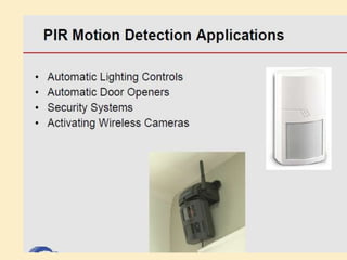
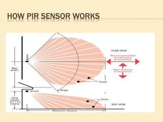
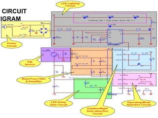
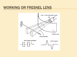


This project presentation summarizes the design and development of a PIR-based lighting control system. The system uses a PIR sensor to detect motion and trigger lights. When no motion is detected, the lights will turn off to save energy. PIR sensors detect infrared radiation emitted from surrounding objects and can be used to control lights in areas that only require occasional illumination, such as pathways, driveways, and gardens. The presentation provides details on PIR sensor components and working, the application circuit design including a power supply, sensor interface, microcontroller, and relay to control lights. It explains how the system can be used to automatically turn lights on when motion is detected and off again after a period of inactivity to provide energy-