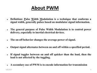
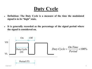
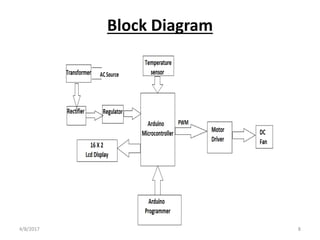
Speed control of DC motor by PWM
technique
Prepared By:
KATHAN SHAH
4/8/2017 1
Introduction to the project
• This project is based on speed control of dc motor using
PWM technique.
• Here we will use temperature controlled dc fan whose
speed is changed according to the level of temperature .
• For measuring the surrounding temperature of system ,
temperature sensor called DHT 22 is used ,which can
also measure humidity .
• speed of the motor is specified for certain range of temp.
through arduino or any equivalent microcontroller.
4/8/2017 2
 Definition: Pulse Width Modulation is a technique that conforms a
signal width, generally pulses based on modulator signal information.
 The general purpose of Pulse Width Modulation is to control power
delivery, especially to inertial electrical devices.
 The on-off behavior changes the average power of signal.
 Output signal alternates between on and off within a specified period.
 If signal toggles between on and off quicker than the load, then the
load is not affected by the toggling.
 A secondary use of PWM is to encode information for transmission
About PWM
4/8/2017 3
Duty Cycle
 Definition: The Duty Cycle is a measure of the time the modulated
signal is in its “high” state.
 It is generally recorded as the percentage of the signal period where
the signal is considered on.
Period (T)
Duty Cycle
(D)
VL
VH
On Off
%100
Period
TimeOn
CycleDuty
4/8/2017 4
Advantages Of PWM Technique
• The main advantage of PWM is that power loss in the switching
devices is very low.
• When a switch is off there is practically no current , and When it is on
and power is being transferred to the load, there is almost no voltage
drop across the switch.
• Power loss , being the product of both , is thus in both cases close to
zero.
• PWM also works well with digital controls , which because of their
on/off nature , can easily set the needed duty cycle.
• Also the temperature sensor DHT22 has low percentage error (0.5%)
and its temperature range is high ( -40 to 80C ) which is considerable
compared to other temperature sensor like LM35 , DHT11 etc.
4/8/2017 5
Hardware Requirements
• Arduino Uno R3: Arduino is a ATMEL based microcontroller which is
used to take a controlling action i.e to change the speed of dc fan
according to the input obtained from the DHT22. It simply adjust the
duty cycle for various temperature range . It is 14 digital I/O pin
device.
• DHT 22: DHT 22 is a family of DHT sensors which is used to measure
the temperature and humidity accurately . It is 4 pin device . It has
internal circuit which can convert analog signal to the digital one
,which can be easily read by microcontroller.
• DC Fan: Here dc fan is just simply a dc motor whose speed is being
changed by varying the duty cycle.
• Power Adapter: power adapter is used to step down the supply ac
voltage in the range of arduino so it can operate safily . We can also use
transformer , rectifier and 7805 regulator set instead of power adapter.
• LCD Display: Here LCD display is used to display the temperature
and duty cycle value . It is 16 X 2 LCD, which is used only for writing
purpose.4/8/2017 6
Software Requirements
• Arduino IDE: Arduino IDE is a software used for the program
development for integrated circuit like Arduino . It is compatible with
any Arduino board like Arduino Uno , LilyPad Arduino ,Red board ,
Arduino Mega , Arduino Leonardo.It can compile the ATMEL based
program generally written in C/C++.It can also compile program .
After compilation we can install program on the Arduino board.
• Proteus: Proteus is used for real time simulation , PCB layout and
schematic arrangement.
• Eagle : Eagle is also used for simulation , schematic circuit and PCB
layout . Here the schematic is made in eagle.
4/8/2017 7
Block Diagram
4/8/2017 8
Application
• Air Conditioning
• Refrigeration System
• Ventilation System
• Transformer OFAF cooling
4/8/2017 9
Future Work
• In future we will prepare flow chart which will give brief information
about the steps of program.
• We will make real time simulation.
• Program implementation in the hardware
4/8/2017 10
THANK YOU
4/8/2017 11

Pwm technique for dc motor Using Arduino

  • 1.
    Speed control ofDC motor by PWM technique Prepared By: KATHAN SHAH 4/8/2017 1
  • 2.
    Introduction to theproject • This project is based on speed control of dc motor using PWM technique. • Here we will use temperature controlled dc fan whose speed is changed according to the level of temperature . • For measuring the surrounding temperature of system , temperature sensor called DHT 22 is used ,which can also measure humidity . • speed of the motor is specified for certain range of temp. through arduino or any equivalent microcontroller. 4/8/2017 2
  • 3.
     Definition: PulseWidth Modulation is a technique that conforms a signal width, generally pulses based on modulator signal information.  The general purpose of Pulse Width Modulation is to control power delivery, especially to inertial electrical devices.  The on-off behavior changes the average power of signal.  Output signal alternates between on and off within a specified period.  If signal toggles between on and off quicker than the load, then the load is not affected by the toggling.  A secondary use of PWM is to encode information for transmission About PWM 4/8/2017 3
  • 4.
    Duty Cycle  Definition:The Duty Cycle is a measure of the time the modulated signal is in its “high” state.  It is generally recorded as the percentage of the signal period where the signal is considered on. Period (T) Duty Cycle (D) VL VH On Off %100 Period TimeOn CycleDuty 4/8/2017 4
  • 5.
    Advantages Of PWMTechnique • The main advantage of PWM is that power loss in the switching devices is very low. • When a switch is off there is practically no current , and When it is on and power is being transferred to the load, there is almost no voltage drop across the switch. • Power loss , being the product of both , is thus in both cases close to zero. • PWM also works well with digital controls , which because of their on/off nature , can easily set the needed duty cycle. • Also the temperature sensor DHT22 has low percentage error (0.5%) and its temperature range is high ( -40 to 80C ) which is considerable compared to other temperature sensor like LM35 , DHT11 etc. 4/8/2017 5
  • 6.
    Hardware Requirements • ArduinoUno R3: Arduino is a ATMEL based microcontroller which is used to take a controlling action i.e to change the speed of dc fan according to the input obtained from the DHT22. It simply adjust the duty cycle for various temperature range . It is 14 digital I/O pin device. • DHT 22: DHT 22 is a family of DHT sensors which is used to measure the temperature and humidity accurately . It is 4 pin device . It has internal circuit which can convert analog signal to the digital one ,which can be easily read by microcontroller. • DC Fan: Here dc fan is just simply a dc motor whose speed is being changed by varying the duty cycle. • Power Adapter: power adapter is used to step down the supply ac voltage in the range of arduino so it can operate safily . We can also use transformer , rectifier and 7805 regulator set instead of power adapter. • LCD Display: Here LCD display is used to display the temperature and duty cycle value . It is 16 X 2 LCD, which is used only for writing purpose.4/8/2017 6
  • 7.
    Software Requirements • ArduinoIDE: Arduino IDE is a software used for the program development for integrated circuit like Arduino . It is compatible with any Arduino board like Arduino Uno , LilyPad Arduino ,Red board , Arduino Mega , Arduino Leonardo.It can compile the ATMEL based program generally written in C/C++.It can also compile program . After compilation we can install program on the Arduino board. • Proteus: Proteus is used for real time simulation , PCB layout and schematic arrangement. • Eagle : Eagle is also used for simulation , schematic circuit and PCB layout . Here the schematic is made in eagle. 4/8/2017 7
  • 8.
  • 9.
    Application • Air Conditioning •Refrigeration System • Ventilation System • Transformer OFAF cooling 4/8/2017 9
  • 10.
    Future Work • Infuture we will prepare flow chart which will give brief information about the steps of program. • We will make real time simulation. • Program implementation in the hardware 4/8/2017 10
  • 11.