This paper presents the implementation of Maximum Power Point Tracking (MPPT) using the Perturb and Observe (P&O) algorithm with variable step size on an Arduino Mega for photovoltaic systems. The experimental results demonstrate that the variable step size P&O algorithm outperforms the fixed step version in terms of response time and oscillations around the maximum power point. Overall, the study highlights the effectiveness of the variable step approach in optimizing energy production from photovoltaic generators.
![International Journal of Power Electronics and Drive System (IJPEDS)
Vol. 8, No. 1, March 2017, pp. 434~443
ISSN: 2088-8694, DOI: 10.11591/ijpeds.v8i1.pp434-443 434
Journal homepage: http://iaesjournal.com/online/index.php/IJPEDS
Implementation in Arduino of MPPT Using Variable Step Size
P&O Algorithm in PV Installations
Mustapha Elyaqouti1
, Safa Hakim2
, Sadik Farhat3
, Lahoussine Bouhouch4
, Ahmed Ihlal5
1,3,4
ERTAIER, ESTA Ibn Zohr University, BP 33/S, 80000 Agadir, Morocco
2
LMTI, FS Ibn Zohr University, BP 8106, 80000 Agadir, Morocco
5
LMER, FS Ibn Zohr University, BP 8106, 80000 Agadir, Morocco
Article Info ABSTRACT
Article history:
Received Oct 31, 2016
Revised Jan 06, 2017
Accepted Jan 16, 2017
In order to maximize the electric energy production of a photovoltaic
generator (PVG), the maximum power point tracking (MPPT) methods are
usually used in photovoltaic systems. The principle of these techniques is to
operate the PVG to the maximum power point (MPP), which depends on the
environmental factors, such as solar irradiance and ambient temperature,
ensuring the optimal power transfer between PVG and load. In this paper, we
present the implementation of two digital MPPT commands using the
Arduino Mega type. The two proposed MPPT controls are based on the
algorithm of perturb and observe (P&O), the first one with fixed perturbation
step and the second one with two perturbations step varying with some
conditions. The experimental results show that the P&O algorithm with
variable step perturbation gives good results compared to the P&O algorithm
with fixed perturbation step in terms of the time response and the oscillations
around the MPP.
Keyword:
Boost converter
MPPT
P&O algorithm
P&O Algorithm with Variable
Step
Photovoltaic energy
Copyright © 2017 Institute of Advanced Engineering and Science.
All rights reserved.
Corresponding Author:
Mustapha Elyaqouti,
ERTAIER,
ESTA Ibn Zohr University,
BP 33/S, 80000 Agadir, Morocco.
Email: elyaqouti@gmail.com
1. INTRODUCTION
The use of renewable energy sources has become increasingly popular around the world, due to their
functioning friendly to the environment [1]. Solar energy is the most promising one. It is a clean and
important source for producing electricity [2],[3]. It has a huge energy potential compared to other
sources [4]. Indeed, with an average irradiation of 5630 Wh/m2
/day, Morocco may cover their energy needs
and export a part of it [5].
However, the output characteristics of PV module depend strongly on the solar radiation attaining
the active surface of PV module and cell temperature of PV module. Furthermore, these parameters have a
variable character depending on the latitude, the orientation of the solar field, the season and the hour of day.
In other terms, the characteristics of the PV panels depend on the parameters continually changing during the
day [6].
These characteristics, specifically those of PVG power P(V), admit a point corresponding to the
maximum power, that is the optimum operating point, named MPP (maximum power point). A converter that
ensures the conversion of electricity exploitable by the user must find and track the MPP continuously on the
curve P (V). In this context, a large number of technical research of the maximum power point tracking
(MPPT: Maximum Power Point Tracker) are well established in the literature.
Indeed, several methods exist, such as: "Perturb and Observe" (P&O) [7]-[10], the "Incremental
conductance" (InC) [11]-[13] which are variants of the "Hill Climbing" [14], Fractional open circuit voltage](https://image.slidesharecdn.com/4530nov6aug12105edit-210605020052/85/Implementation-in-Arduino-of-MPPT-Using-Variable-Step-Size-P-O-Algorithm-in-PV-Installations-1-320.jpg)
![International Journal of Power Electronics and Drive System (IJPEDS)
Vol. 8, No. 1, March 2017, pp. 434~443
ISSN: 2088-8694, DOI: 10.11591/ijpeds.v8i1.pp434-443 434
Journal homepage: http://iaesjournal.com/online/index.php/IJPEDS
Implementation in Arduino of MPPT Using Variable Step Size
P&O Algorithm in PV Installations
Mustapha Elyaqouti1
, Safa Hakim2
, Sadik Farhat3
, Lahoussine Bouhouch4
, Ahmed Ihlal5
1,3,4
ERTAIER, ESTA Ibn Zohr University, BP 33/S, 80000 Agadir, Morocco
2
LMTI, FS Ibn Zohr University, BP 8106, 80000 Agadir, Morocco
5
LMER, FS Ibn Zohr University, BP 8106, 80000 Agadir, Morocco
Article Info ABSTRACT
Article history:
Received Oct 31, 2016
Revised Jan 06, 2017
Accepted Jan 16, 2017
In order to maximize the electric energy production of a photovoltaic
generator (PVG), the maximum power point tracking (MPPT) methods are
usually used in photovoltaic systems. The principle of these techniques is to
operate the PVG to the maximum power point (MPP), which depends on the
environmental factors, such as solar irradiance and ambient temperature,
ensuring the optimal power transfer between PVG and load. In this paper, we
present the implementation of two digital MPPT commands using the
Arduino Mega type. The two proposed MPPT controls are based on the
algorithm of perturb and observe (P&O), the first one with fixed perturbation
step and the second one with two perturbations step varying with some
conditions. The experimental results show that the P&O algorithm with
variable step perturbation gives good results compared to the P&O algorithm
with fixed perturbation step in terms of the time response and the oscillations
around the MPP.
Keyword:
Boost converter
MPPT
P&O algorithm
P&O Algorithm with Variable
Step
Photovoltaic energy
Copyright © 2017 Institute of Advanced Engineering and Science.
All rights reserved.
Corresponding Author:
Mustapha Elyaqouti,
ERTAIER,
ESTA Ibn Zohr University,
BP 33/S, 80000 Agadir, Morocco.
Email: elyaqouti@gmail.com
1. INTRODUCTION
The use of renewable energy sources has become increasingly popular around the world, due to their
functioning friendly to the environment [1]. Solar energy is the most promising one. It is a clean and
important source for producing electricity [2],[3]. It has a huge energy potential compared to other
sources [4]. Indeed, with an average irradiation of 5630 Wh/m2
/day, Morocco may cover their energy needs
and export a part of it [5].
However, the output characteristics of PV module depend strongly on the solar radiation attaining
the active surface of PV module and cell temperature of PV module. Furthermore, these parameters have a
variable character depending on the latitude, the orientation of the solar field, the season and the hour of day.
In other terms, the characteristics of the PV panels depend on the parameters continually changing during the
day [6].
These characteristics, specifically those of PVG power P(V), admit a point corresponding to the
maximum power, that is the optimum operating point, named MPP (maximum power point). A converter that
ensures the conversion of electricity exploitable by the user must find and track the MPP continuously on the
curve P (V). In this context, a large number of technical research of the maximum power point tracking
(MPPT: Maximum Power Point Tracker) are well established in the literature.
Indeed, several methods exist, such as: "Perturb and Observe" (P&O) [7]-[10], the "Incremental
conductance" (InC) [11]-[13] which are variants of the "Hill Climbing" [14], Fractional open circuit voltage](https://image.slidesharecdn.com/4530nov6aug12105edit-210605020052/75/Implementation-in-Arduino-of-MPPT-Using-Variable-Step-Size-P-O-Algorithm-in-PV-Installations-1-2048.jpg)
![IJPEDS ISSN: 2088-8694
Implementation in Arduino of MPPT Using Variable Step Size P&O Algorithm .... (Mustapha Elyaqouti)
435
(FCO) or Fractional short circuit current algorithm (FCC) [15],[16], the techniques of artificial intelligence,
such as the control by fuzzy logic [17]-[19], by genetic algorithm [20] or by neural networks [21]-[23] etc.
Among these techniques, the "P&O" Classic is the most popular and easiest way to implement [24].
In this paper, we focus on the implementation of the command "P&O" classic with fixed
perturbation step as well as variable step. This command is implemented on the Arduino board. Our paper is
organized as follows: After this introduction, we will describe in the second part the test bench and
measurement, then in the third part we will present the modeling of the Boost converter as well as their
MPPT techniques. The last part will be devoted to the exhibition and analysis of experimental results
followed by a conclusion.
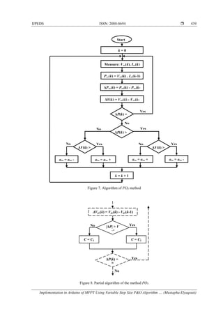
2. TEST BENCH AND MEASUREMENT
2.1. Test bench
The present conversion chain constituting our test bench comprises a photovoltaic generator (PVG),
supplying a DC load through a boost converter. This latter is controlled by an MPPT control type "P&O" in
order to have the power supplied by the PVG corresponds to the maximum power generated. The block
diagram of this system is illustrated in Figure 1.
Figure 1. Synoptic scheme of the realized PV conversion chain
The principle measuring adopted in this test bench, is to take the current Ipv supplied by the PVG as
well as the voltage Vpv between its terminals. These variables Ipv and Vpv are delivered by the current and
voltage sensors connected to the inputs of the analog digital converter integrated in the Arduino board type
Mega 2560. This latter is programmed to be used as an acquisition card transmitting in real time, the
numerical values acquired (Ipv, Vpv) to a computer through an RS232 / USB serial converter. Figure 2 below
shows the realized prototype to validate the developed MPPT algorithms.
Figure 2. Realized test Bench
Load
Driver
Boost
Converter
Arduino
Mega 2560](https://image.slidesharecdn.com/4530nov6aug12105edit-210605020052/85/Implementation-in-Arduino-of-MPPT-Using-Variable-Step-Size-P-O-Algorithm-in-PV-Installations-2-320.jpg)
![ ISSN: 2088-8694
IJPEDS Vol. 8, No. 1, March 2017 : 434 – 443
436
In terms of treatment unit, we have developed under the Matlab-Simulink environment a program
that ensures the capture of the data (Ipv, Vpv) that will serve as inputs for the MPPT algorithms that we have
developed. These algorithms determine the appropriate duty cycle pv for the Arduino board in order to
produce a PWM signal (Pulse Width Modulation) this latter attack a driver amplifying the current control of
the MOSFET transistor of Boost converter.
Concerning the capture, archiving and treatment of Ipv and Vpv sizes, the Figure 3 shows the block
diagram for the program that we have developed under Matlab-Simulink. This allows us to visualize in real
time the characteristics Ipv = f(t), Vpv = f(t), Ipv = f(Vpv) and the evolution of the power Ppv = f(Vpv) of PV
module.
Figure 3. Acquisition program through the Arduino board and data processing under Matlab-Simulink
2.2. PV Module
The PVG used in our investigations is BP Solar MSX-64. Their electrical specifications provided by
the manufacturer are given in Table 1 [25], under the standard test conditions STC (Standard Test
Conditions: G = 1000 W/m2
, AM 1.5, T = 25°C). The results of characterization of this PVG using many
models have been the subject of the publication [26].
Table 1. Electrical characteristics of the PV panel MSX-64 in STC[25]
Parameters Value
Maximum power Pmax 64 W
Voltage at maximum power Vmpp 17.5 V
Current at maximum power Impp 3.66 A
Short-circuit current Isc 4 A
Open-circuit voltage Voc 21.3 V
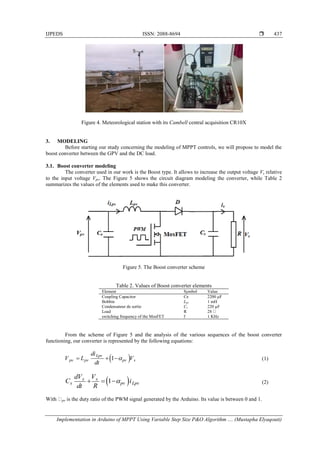
2.3. Bench measurement of meteorological conditions
In order to have the meteorological conditions of solar irradiance G and temperature T, under which
the quantities (Ipv, Vpv) are recorded, the Fig.4 illustrates the test bench installed in our laboratory of EST
Agadir. Indeed, the solar irradiance G and the temperature T are measured by means of various sensors
managed by Cambell acquisition unit of CR10X kind. The data G and T are collected every 10 seconds,
depending on the configuration of the data acquisition unit [27].](https://image.slidesharecdn.com/4530nov6aug12105edit-210605020052/85/Implementation-in-Arduino-of-MPPT-Using-Variable-Step-Size-P-O-Algorithm-in-PV-Installations-3-320.jpg)
![ ISSN: 2088-8694
IJPEDS Vol. 8, No. 1, March 2017 : 434 – 443
440
4. EXPERIMENTAL RESULTS
In order to test the performance of the MPPT algorithms cited in Part 3.2, we are going to plot the
output Ipv = f(Vpv) and Ppv = f(Vpv) of our PVG for different values of solar irradiance G and temperature T.
For this, we vary the duty cycle pv of 5% to 95% with a fixed increment. The obtained measurements allow
us to determine the maximum power Pmax generated by our PVG. And then Pmax will be compared to the
maximum power Pmpp extracted by either algorithms POF and POV. We note that G and T values measured by
the weather station in Figure 4, are considered constant throughout the characterization duration.
The obtained measurements allow us to represent in Figure 9 the characteristics Ipv = f(Vpv) and
Ppv = f(Vpv) for G = 982 W/m2
corresponding to an irradiance received on the active surface of the PV
module.
Figure 9. Experimental characteristicsIpv = f(Vpv) et Ppv = f(Vpv) of PVGMSX64type forG = 982 W/m2
et
T = 25.1°C
Figure 10 to 12 summarizes the experimental responses of power Ppv, of voltage Vpv and of current
Ipv under POF and POV methods. For the first method POF, we have presented two responses, one with a
fixed perturbation step C = 0.01 during the measurement, and another with C = 0.001 which does not vary
during the test. While for the second method POV, we have presented in the same figures the experimental
responses Ppv, Vpv and Ipv with a step depending on the proposed algorithm and can be C1 = 0.01 or
C2 = 0.001, during the time of characterization.
Figure 10. Experimental response of the power Ppv
0 5 10 15 20
0
1
2
3
4
5
Vpv [ V ]
Ipv
[
A
]
0 5 10 15 20
0
10
20
30
40
50
Ppv
[
W
]
0 2 4 6 8 10 12 14
0
10
20
30
40
50
Time [ S ]
Ppv
[
W
]
POF with C=0.01
POF with C=0.001
POV
10](https://image.slidesharecdn.com/4530nov6aug12105edit-210605020052/85/Implementation-in-Arduino-of-MPPT-Using-Variable-Step-Size-P-O-Algorithm-in-PV-Installations-7-320.jpg)
![IJPEDS ISSN: 2088-8694
Implementation in Arduino of MPPT Using Variable Step Size P&O Algorithm .... (Mustapha Elyaqouti)
441
Figure 11. Experimental response of voltage Vpv
Figure 12. Experimental response of current Ipv
After analyzing these figures, we notice that for the algorithm POF with a fixed step C = 0.01 along
the measurement, the operating point reaches the MPP in 1.65 s against 3.72 s for a perturbation step
C = 0.001 also invariable during the test. As a result, the response is logically faster for the big step C = 0.01.
However, the oscillations around the MPP are less important for the small step C = 0.001. This allows us to
confirm that with a big step, the algorithm is faster but less accurate. Whereas, with a small step, the
algorithm is slower but fairly accurate. Regarding the algorithm of the POV technique with C1 = 0.01 and
C2 = 0.001, the operating point reached the MPP in 2.47 s with small oscillations around the MPP which is
identical to the method POF with low step. Therefore, this algorithm shows a good compromise between
speed and accuracy.
5. CONCLUSION
In this paper, we have presented the implementation of the command "P&O" with a fixed
perturbation step (POF) and the command "P&O" with a double perturbation step (POV) using the arduino
Mega board. The experimental result shows that the command POV gives good results compared to the
control POF in terms of time response and oscillations around the MPP.
REFERENCES
[1] M. A. El-Hakeem, “Solar Irradiance estimation of photovoltaic module besed on Thevenin equivalent circuit,”
International Journal of Renewable Energy Research, vol/issue: 5(4), pp. 971-977, 2015.
[2] M. E. Basoglu and B. Çakir, “Comparisons of MPPT performances of insolated and non-isolated DC-DC
converters by using a new approach,” Renewable and Sustainable Energy Reviews, vol. 60, pp. 1100-1113, 2016.
0 2 4 6 8 10 12 14
0
5
10
15
Time [ S ]
Vpv
[
V
]
POF with C=0.01
POF with C=0.001
POV
0 2 4 6 8 10 12 14
0
1
2
3
4
Time [ S ]
Ipv
[
A
]
POF with C=0.01
POF with C=0.001
POV
8
12
14
16
Time [ S ]
Vpv
[
V
]
8
3.2
3.4
3.6
3.8
Time [ S ]
Ipv
[
A
]](https://image.slidesharecdn.com/4530nov6aug12105edit-210605020052/85/Implementation-in-Arduino-of-MPPT-Using-Variable-Step-Size-P-O-Algorithm-in-PV-Installations-8-320.jpg)
![ ISSN: 2088-8694
IJPEDS Vol. 8, No. 1, March 2017 : 434 – 443
442
[3] N. Kumar, et al., “Prediction of solar energy based on intelligent ANN modelling,” International Journal of
Renewable Energy Research, vol/issue: 6(1), pp. 183-188, 2016.
[4] R. K. Tarai and P. Kale, “Development of rasterized mapusing PVGIS for assessment of solar PV energy potential
of Odisha,” International Journal of Renewable Energy Research, vol/issue: 6(1), pp. 61-72, 2016.
[5] A. A. Merrouni, et al., “Integration of PV in the Moroccan building: Simulation of a small roof system installed in
Eastern Morocco,” International Journal of Renewable Energy Research, vol/issue: 6(1), pp. 183-188, 2016.
[6] K. K. Kumar, et al., “Implementation of MPPT algorithm for solar photovoltaic cell by comparing short-circuit
method and incremental conductance method,” Procedia Technology, vol. 12, pp. 705-715, 2014.
[7] J. Ahmed and Z. Salam, “An improved perturb and observe (P&O) maximum power point traking (MPPT)
algorithm for higher efficiency,” Applied Energy, vol. 150, pp. 97-108, 2015.
[8] S. Farhat, et al., “P&O and Incremental conductance MPPT implementation,” International Review of Electrical
Engineering (IREE), vol/issue: 10(1), pp. 116-122, 2015.
[9] A. K. Abdelsalam, et al., “High-Performance adaptive Perturb and Observe MPPT technique for photovoltaic-
Based Microgrids,” IEEE Transactions on Power Electronics, vol/issue: 26(4), pp. 1010-1021, 2011.
[10] N. S. D'Souza, et al., “Comparative study of variable size perturbation and observation maximum power point
trackers for PV systems,” Electric Power Systems Research, vol/issue: 80(3), pp. 296-305, 2010.
[11] P. S. Kumar, et al., “Analyse and enhancement of PV efficiency with Incremental Conductance MPPT technique
under non-linear loading conditions,” Renewable Energy, vol. 81, pp. 543-550, 2015.
[12] K. Ishaque, et al., “The performance of perturb and observe and incremental conductance maximum power point
tracking method under dynamic weather conditions,” Applied Energy, vol. 119, pp. 228-236, 2014.
[13] M. B. Kalashani and M. Farsadi, “New Structure for Photovoltaic Systems with Maximum Power Point Tracking
Ability,” International Journal of Power Electronics and Drive System, vol/issue: 4(4), pp. 489-498, 2014.
[14] K. Hirech, et al., “Photovoltaic system equipped with a reliable and efficient regulator/MPPT and energy flow
controller,” International Review of Electrical Engineering (IREE), vol/issue: 10(1), pp. 131-144, 2015.
[15] M. A. Enany, et al., “Modeling and evaluation of main maximum power point tracking algorithms for photovoltaics
systems,” Renewable and Sustainable Energy Reviews, vol. 58, pp. 1578-1586, 2016.
[16] S. Selvan, et al., “A Review on Photovoltaic MPPT Algorithms,” International Journal of Electrical and Computer
Engineering (IJECE), vol/issue: 6(2), pp. 567-582, 2016.
[17] B. Bendib, et al., “A Survey of the most used MPPT methods: Conventional and advanced algorithms applied for
photovoltaic systems,” Renewable and Sustainable Energy Reviews, vol. 45, pp. 637-648, 2015.
[18] Y. T. Chen, et al., “A fuzzy-logic based auto-scaling variable step-size MPPT method for PV systems,” Solar
Energy, vol. 126, pp. 53-63, 2016.
[19] C. Sharma and A. Jain, “Performance Comparison of PID and Fuzzy Controllers in Distributed MPPT,”
International Journal of Power Electronics and Drive System (IJPEDS), vol/issue: 6(3), pp. 625-635, 2015.
[20] S. Daraban, et al., “A novel MPPT (Maximun Power Point Tracking) algorithm based on a modified genetic
algorithm specialized on tracking the global maximum power point in photovoltaic systems affected by partial
shading,” Energy, vol. 74, pp. 374-388, 2014.
[21] P. Kofinus, et al., “An Intelligent MPPT controller based on direct neural control for partially shaded PV system,”
Energy and Building, vol. 90, pp. 51-64, 2015.
[22] A. A. Kulaksiz and R. Akkaya, “A genetic algorithm optimized ANN-based MPPT algorithm for a stand-alone PV
system with induction motor drive,” Solar Energy, vol/issue: 86(9), pp. 2366-2375, 2012.
[23] M. Yaichi, et al., “A Neural Network MPPT Technique Controller for Photovoltaic Pumping System,”
International Journal of Power Electronics and Drive System (IJPEDS), vol/issue: 4(2), pp. 241-255, 2014.
[24] H. Rezk and E. S. Hasaneen, “A new Matlab/Simulink model of triple-junction solar cell and MPPT based on
artificial neural networks for photovoltaic energy systems,” Ain Shams Engineering Journal, vol. 6, pp. 873-881,
2015.
[25] Web site: https://www.smud.org/en/about-smud/environment/renewable-energy/documents/solar-regatta-
photovoltaic-specs.pdf
[26] M. Elyaqouti, et al., “Etude comparative de modèles de caractérisation et extraction des paramètres d’un générateur
photovoltaïque,” 9ème Congrès Francophone de Génie des Procédés, Agadir, 28-30 Avril 2014.
[27] S. Farhat, et al., “MPPT Efficiency test by neural networks and P&O algorithm,” International Review of Electrical
Engineering (IREE), vol/issue: 8(5), pp. 1548-1554, 2013.
BIOGRAPHIES OF AUTHORS
Mustapha Elyaqouti was born in Agadir, Morocco, in 1984. He received the technical
University degree (DUT) in Electrical Engineering from the High School of Technologies of
Agadir (EST Agadir), in 2006. He received his BSc degree in physics and a post graduate degree
in Materials Engineering and energetic environment from Ibn Zohr University, in 2010 and
2012. His research, in the context of national doctoral thesis, focuses on the thematic of
Renewable Energies. The doctoral investigation took place in the Research Team in advanced
Technologies and Engineering of Renewable Energies (ERTAIER) Agadir Morocco](https://image.slidesharecdn.com/4530nov6aug12105edit-210605020052/85/Implementation-in-Arduino-of-MPPT-Using-Variable-Step-Size-P-O-Algorithm-in-PV-Installations-9-320.jpg)